warwick.ac.uk/lib-publications
A Thesis Submitted for the Degree of PhD at the University of Warwick
Permanent WRAP URL:
http://wrap.warwick.ac.uk/110865
Copyright and reuse:
This thesis is made available online and is protected by original copyright.
Please scroll down to view the document itself.
Please refer to the repository record for this item for information to help you to cite it.
Our policy information is available from the repository home page.
THE BRITISH LIBRARY
BRITISH THESIS SERVICE
TITLE
FEA TURE BASED COMPUTER AIDED
PRO C ESS PLANNING
AUTHOR
Eur Ing Dilip
PA TH
DEGREE
Ph.D
AWARDING
BODY
W a rw ic k University
DATE
1995
THESIS
NUMBER
DX201885
THIS THESIS HAS BEEN MICROFILMED EXACTLY AS RECEIVED
The quality of this reproduction is dependent upon the quality of the original thesis submitted for microfilming. Every effort has been made ro ensure the highest quality of reproduction. Some pages may have indistinct print, especially ft the original papers were poorly produced or if the awarding body sent an inferior copy. If pages are missing, please contact the awarding body which granted the degree.
Previously copyrighted materials (Journal articles, published texts, etc.) are not filmed.
This copy of the thesis has been supplied on condition that anyone who consults it Is understood to recognise that its copyright rests with its author and that no information derived from it may be published without the author's prior written consent.
Feature Based
Computer Aided Process Planning
by
Eur Ing Dilip Patil
BE (Mech), MTech (Production Science & Technology), MIE,
MIMechE, CEng.
A thesis submitted for the Degree o f
Doctor o f Philosophy
W ARW ICK
SUMM ARY
This research attempts to study, plan and develop an integrated feature based
CAPP system that generates automated process plans for machining prismatic
components. The CAPP system comprises a STEP compliant feature based
commercial CAD system and the Smalltalk object oriented system. A library of
features has been developed that is based on STEP based form feature taxonomy but
modified to communicate the manufacturing intent and feature aggregation. The CAPP
system has been developed to represent the product, process and resource domain
knowledge with a number of object hierarchies, communication methods, and the user
interface that would suit the concurrent engineering needs. In addition, suitable
geometric and process reasoning methods have been developed in the CAPP system
that use the feature based component design data to generate automated process plans.
The research also attempts to identify the problems in feature based process
planning and discusses the possible solutions. A solution to the side feature interaction
problem has been implemented in the CAPP system.
The CAPP system test results have demonstrated that the proposed approach has
been successful and has a great potential for further improvements in terms of
flexibility, modularity, emerging data exchange standards, and case in customising the
CAPP system.
TABLE OF CONTENTS
Summary... i
Acknowledgements... x
Declarations... xi
1. SCOPE AND OBJECTIVES OF THE RESEARCH...1
1.1 Introduction...1
1.2 Overview of Process Planning... 3
1.3 The Current CAPP Systems... 4
1.4 The Success of CAPP Research... 4
1.5 Scope for Research in CAPP... 5
1.6 The Objectives of the Research... 6
1.7 Justification of the Approach... 7
1.8 The Thesis Structure... 8
2. CAPP: TOOLS AND TECHNIQUES... 10
2.1 Process Planning in Manufacturing...10
2.2 The CAPP Approaches... 11
2.2.1 The Variant Approach...11
2.2.2 The Generative Approach... 12
2.2.3 The Semi-Generative Approach...15
2.3 Commercial CAPP Systems...15
2.4 CAPP System Development Techniques... 19
2.5 Design Representation Techniques...20
2.5.1 Group Technology... 20
2.5.2 Computer Aided Design (CAD)...23
2.5.3 Computer Aided Manufacturing (CAM) from C A D ... 27
2.5.4 Feature Recognition from CAD Model...28
2.5.6 Design By Feature... 32
2.5.7 Product Modelling with Concurrent Engineering... 37
2.5.8 Knowledge Based CAD Modelling... 38
2.5.9 CAD/CAD Data Exchange... 39
2.5.10 STEP/ISO 10303... 41
2.5.11 EXPRESS and Object Oriented Language... 42
2.6 Process Knowledge Representation... 43
2.6.1 Decision Tables...43
2.6.2 Decision Tree... 44
2.6.3 Conventional Programming Languages... 44
2.6.4 Artificial Intelligence (AI) Techniques... 45
2.7 Databases...50
2.8 Conclusions... 52
3. PRODUCT DESIGN REPRESENTATION... 55
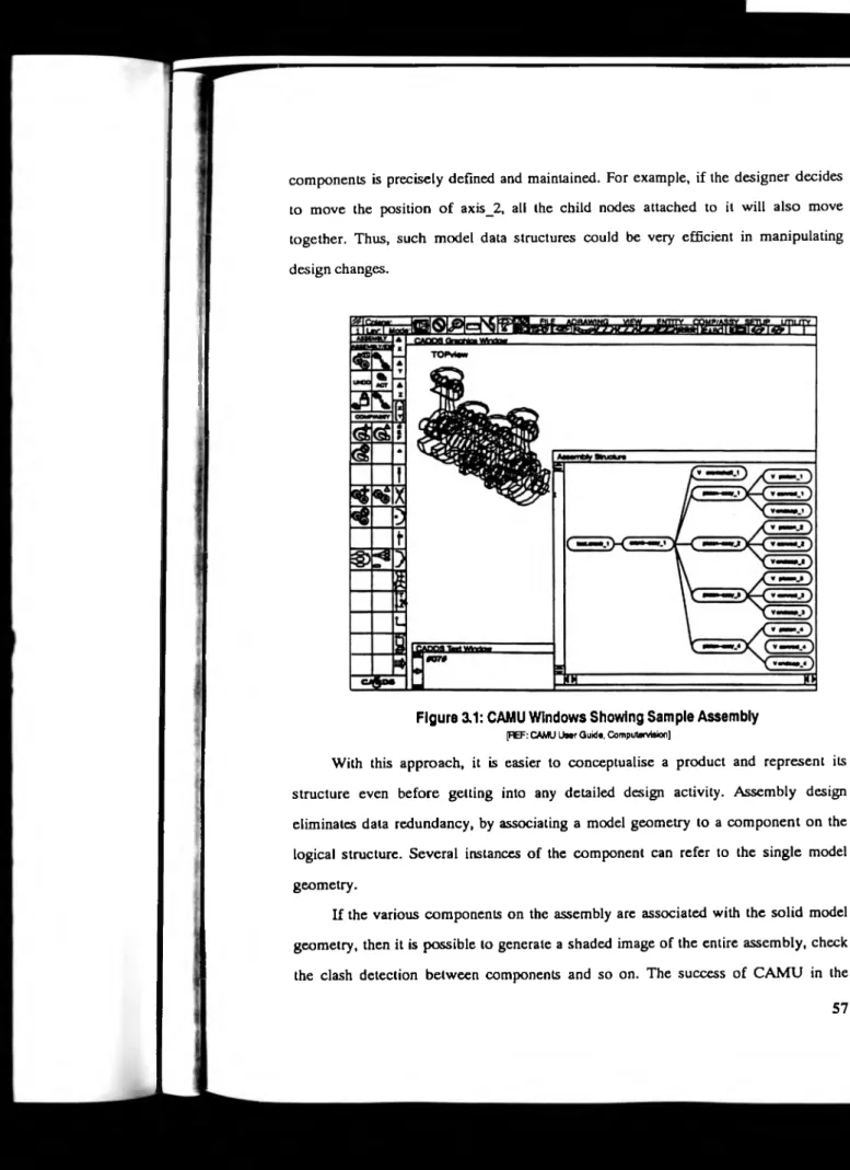
3.1 Concurrent Assembly Design... 55
3.1.1 CAMU and Engineering Data Management System (ED M )... 58
3.1.2 CAMU and Configuration Access... 60
3.2 CAMU, EDM and CAPP...61
3.3 Feature Based Modelling... 63
3.3.1 The System Form Features... 63
3.3.2 Modelling With Features... 65
3.3.3 Model as a Feature Tree... 65
3.3.4 Limitations of System Form Features for C A PP...66
3.3.5 User Defined Features...66
3.4 Form Features and Manufacturing Intent...67
3.5 The Manufacturing Intent... ... 68
3.6 Tolerancing by Features... ... 68
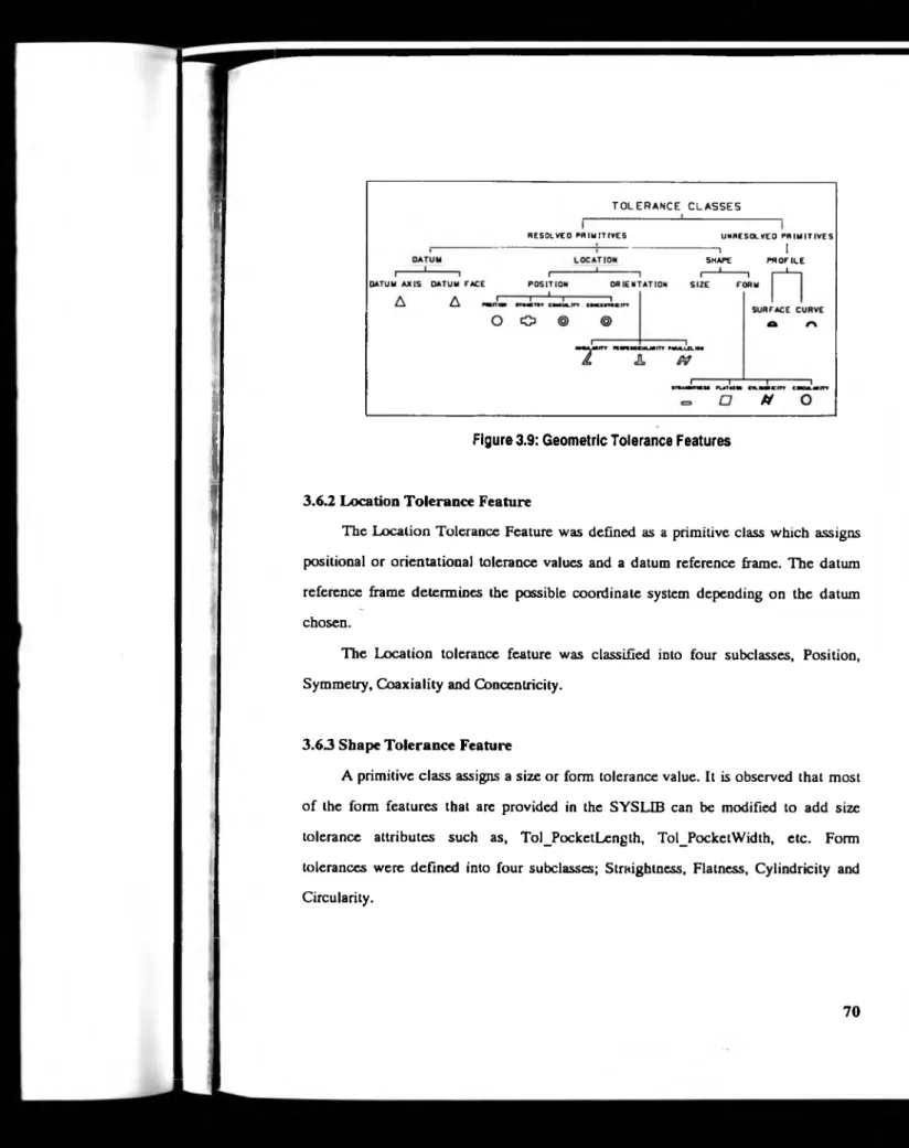
3.6.1 Datum Feature... 69
3.6.2 Location Tolerance Feature... ... 70
3.6.3 Shape Tolerance Feature... 70
3.6.4 Profile Tolerance Feature... 71
3.6.5 Tolerancing the Feature Based Model...71
3.7 Manufacturing Features... 71
3.7.1 Surface Finish...71
3.7.2 Machine or Not_Machined... 71
3.7.3 Raw Material Stock...72
3.7.4 Fixture Feature... 73
3.7.5 Assigning Manufacturing Features...73
3.8 Features and Creativity... 73
3.9 CADDS5 System User Limitations... 74
3.10 Modified Design Representation Scheme...75
4. CAPP SYSTEM DEVELOPMENT PLANNING... 76
4.1 CAPP System Planning Considerations... 76
4.2 CAPP System Objectives...78
4.3 The Programming Tool... 78
4.4 The Initial System Planning... 79
4.4.1 The Resource Database... 81
4.4.2 Resource Database Input/Output... 86
4.4.3 Resource Queries... 87
4.5 Review Of The Initial Plan... 87
4.6 The Object Oriented Programming T ool...88
4.7 Final CAPP System Plan... ... 89
5. CAPP SYSTEM DEVELOPMENT... 90
5.2 Product Knowledge Representation... 93
5.3 Process Knowledge Representation... 95
5.4 Resource Knowledge Representation... 99
5.5 The System Communication Interface... 102
5.6 Geometric Reasoning Technique...103
5.7 Process Reasoning Technique...107
5.8 Manual Planning Technique... 112
5.9 Process Plan Report Generation...114
5.10 Conclusions...116
6. CAPP SYSTEM RESULTS...118
6.1 Product Design Representation...118
6.2 Process Plan Generation... 120
6.3 The Resource Representation...122
6.4 Conclusions...123
7. PROBLEMS IN FEATURE BASED TECHNIQUES...125
7.1 Documented, Complementary and Undocumented features...125
7.2 Feature interaction...126
7.3 Feature Based Modelling Systems... 128
7.4 Workpiece selection & stock thickness...129
7.5 Plan optimisation for features and complete part... 129
7.6 Research approach to the problems in feature based techniques... 130
7.6.1 Design to Manufacturing feature mapping...130
7.6.2 Young's feature interaction using SDSM queries... 131
7.6.3 Mapping machining features by recognition approach... 132
7.6.4 Hybrid feature modelling system...134
7.6.5 Explicit feature interaction modelling...135
7.6.6 Workpiece selection...135
7.6.7 Plan Optimisation Strategies... 136
7.7 Probable Solutions to Problems in Feature Based C A PP...138
7.7.1 Feature Proliferation and User Interface...138
7.7.1.1 Training on Standard Feature Taxonomy...139
1.1 A.2 Graphic User Interface... 139
7.7.1.3 The Rover Experience... 139
7.7.2 Feature Interaction...140
7.7.3 Feature Mapping...142
7.7.4 Operation Planning and Tool Selection... 144
7.7.5 Process Plan Input to NC Programming...147
7.7.6 Mapping of Undocumented Features...149
7.7.7 Process Plan Optimisation... 150
7.7.7.1 Feature Level Optimisation... 151
7.7.7.2 Component level plan optimisation... 154
8. CAPP FOR SIDE FEATURE INTERACTION... 158
8.1 Side feature interaction attributes... 158
8.2 Modifications to Import Feature interface... 159
8.3 Feature topology and geometry... 160
8.4 Detection of Interacting Feature Cluster... 161
8.5 Feature Validation... 161
8.6 Feature Mapping... 162
8.6.1 Tool Selection Method... 164
8.6.2 Feature profile union or subtraction... 165
8.7 Process plan generation for cluster pockets...167
8.7.1 Pocket comer finishing operation... 168
8.9 Test Results... 168
9. DISCUSSION... 170
9.1 The Product Design Representation... 170
9.2 Geometric Reasoning... 173
9.3 Process Knowledge and Reasoning... 176
9.4 Resource integration...179
9.5 General... 181
9.6 Future Research... 182
9.6.1 Enhancing the Current Implementation... 182
9.6.2 Global CAPP research... 183
10. CONCLUSIONS... 185
REFERENCES... 189
APPENDIX A ... 209
APPENDIX B ... 222
APPENDIX C ...227
APPENDIX D ... 229
APPENDIX E ... 242
APPENDIX F...249
LIST OF ILLUSTRATIONS
Figure2.1 - Schematic Representation of the PARI System...13
Figure2.2 - Sandvik COROCIM System...16
Figure2.3 - Coding of a Round Part... 21
Figure2.4 - A B-rep Solid Model...24
Figure2.5 - The CSG T ree... ... 26
Figure2.6 - AAG for Sample Part & AAG for Feature Instances... 30
Figure2.7 - CAD Data Exchange Standards Development... 40
Figure2.8 - Decision Table and Decision Tree... 44
Figure2.9 - Frame Representation... 48
Figure2.10 - Semantic Nets... 50
Figure3.1 - CAMU Windows Showing Sample Assembly... 57
Figure3.2 - Assembly Structure of an Assembly named Wagon... 58
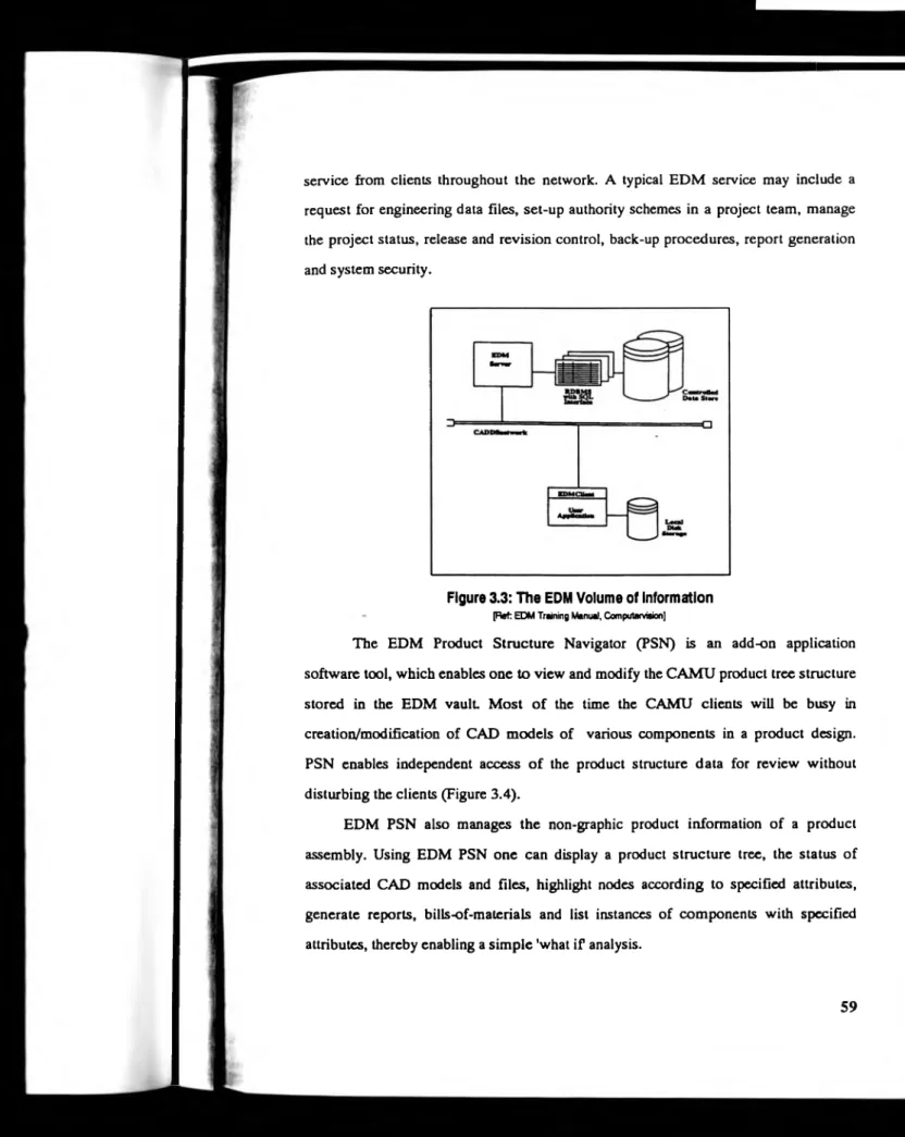
Figure3.3 - The EDM Volume of Information... 59
Figure3.4 - Product Structure Navigator Inputs and Outputs...60
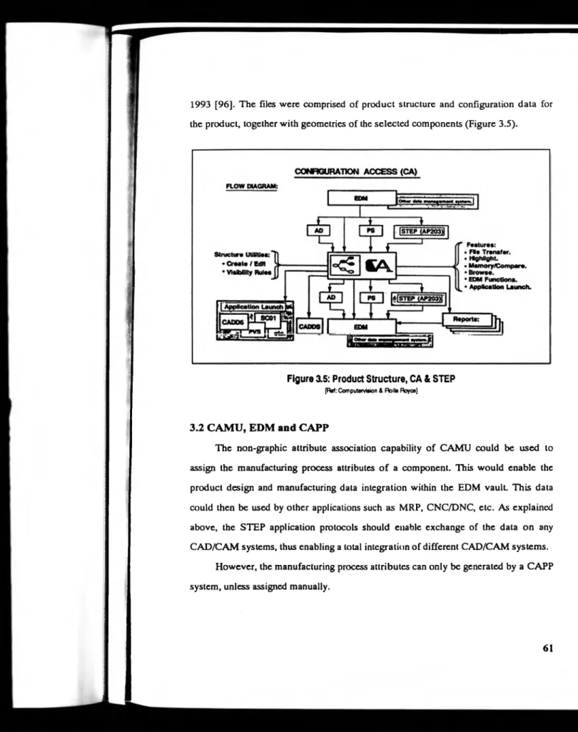
Figure3.5 - Product Structure, CA & STEP... 61
Figure3.6 - Variant or Generative CAPP Options...62
Figure3.7 - The Role of Configuration Access... 62
Figure3.8 - A Typical Form Feature Schema... 64
Figure3.9 - Geometric Tolerance Features... 70
Figurc3.10- FBM with Tolerance Features... 72
Figure3.11 - Manufacturing Features... 72
Figure3.12 - FBM with Manufacturing Features... 73
Figure4.1 - The Global Domains in Manufacturing Planning...77
Figure4.2 - The Initial CAPP System Plan... 79
Figure4.3 - Entity Relationships...82
Figure4.4 - Tool Component Relationships... 84
Figure4.5 - Resource Entity Relationships... 85
Figure5.1 - Object Concepts... 91
Figure5.2 - The Product Definition User Interface... 94
Figure5.3 - Operations and Pre-Machining State... 96
Figure5.4 - Machining Process Classification...98
Figure5.5- The Process User Interface... 99
Figure5.6 - Machine Tool Classification...100
Figure5.7 - The Machine and Tool Resource User Interface... 100
Figure5.8 - The Material Resource User Interface... 102
Figure5.9 - Interpretation of the Additive Feature for 'Solid' Stock... 104
Figure5.10 - Data Flow Diagram for Process Reasoning Technique... 108
Figure5.ll - Data Flow Diagram for Manual Process Assignment... 114
Figure7.1 - Interacting Feature Cluster Formed by Documented Features... 125
Figure7.2A - Overlap, Precedence & Thin Wall Interactions... 127
Figure7.1B - View ‘A ’ of the model in 7.2A showing stock around component...127
Figure7.3 - Major Steps in Shah’s Design to Machining Feature Mapping... 130
Figure7.4 - Illustration of Interacting Features...142
Figure7.5 - Elementary Tool Motion Cross-sections... 145
Figure7.6 - Illustration of Complementary Machining Features... 147
Figure7.7 - Edge Topology of interacting feature instances... 147
Figures. 1 - Feature edge topology...160
Figure8.2 - Depth based Mapping...163
ACKNOWLEDGEMENTS
I would like to extend my gratitude to my supervisor Mr John Hill, for his
guidance and help. Many thanks to my friends : nd colleagues within the Warwick
Manufacturing Group, especially to Mr Neil Davis of Simulation Group for providing
the Smalltalk object oriented programming software. Without his help this non funded
part time research would not have been able to achieve its complete goal.
j
r
t
DECLARATIONS
I declare that the work presented herein is my own work and has not been
1. SC O PE AND OBJECTIVES OF THE RESEARCH
1.1 Introduction
Global competition has led manufacturers to search for new ways to reduce the
time-to-market, and product costs while improving quality. The search has led to the
basic design, manufacturing and management concepts to be used throughout the
product life-cycle. It has been realised, that these concepts should be reviewed, with
manufacturers adopting a concurrent engineering strategy, as opposed to a traditional
serial engineering approach. It is a strategy whereby all members of the product
engineering team, from design to production and marketing, work from a common
product master model. CAD/CAM has become the core technology in this strategy.
A key to the success of integrated product development is the free sharing of
product data between design and manufacturing. The exchange of product model data
between different CAD/CAM systems is rather tedious because of the differences in
the internal geometry representation, and the ambiguous definitions of the exchange
standards. In response to this need, major IT suppliers and users have collaborated to
develop an industry-standard called STEP (STandard for Exchange of Product model
data). The STEP standard is aimed at common specifications for communicating
product information at all stages of the product life-cycle.
Process planning can be seen as an activity which integrates knowledge about
products and resources. It refers to the product design, and decides how to
manufacture it within the resource constraints p esenl. Recognising its importance,
considerable research efforts have been made for the past two decades to automate
process planning by Computer Aided Process Planning (CAPP) methods.
The research efforts have tried to use various feature methodologies as a
medium of communication of the design representation to manufacturing. A broad
definition of a feature in the engineering domain is given by Pratt and Wilson [66] as: 'a
region of interest on the surface of a part'. The broad definition is necessary to
encompass the variety of items, that engineers consider to be features of a part, at
various stages in the design and manufacturing applications.
The same feature could have a different meaning within different applications.
For example, a bearing support is a functional feature in the conceptual design phase
which may express the function and not the shape. In the later design phase, the
bearing support could be described with a geometry of a cylindrical surface. When a
geometry of a feature is considered, it is usually called a form feature [67, 84]. Finally,
in the process planning phase, the bearing support form is viewed as a drilled or bored
hole which may be referred to as a manufacturing feature.
The functional features associated with textual information without any
geometry are of little use in the automation of downstream applications, such as
process planning and NC programming. However, form features are suitable for such
applications. In many cases the form feature will elso be a manufacturing feature. For
example, a cylindrical surface geometry of a form feature in the above discussion will
also be a manufacturing feature (a hole). Thus, form features may be used as a medium
of communication of features from design to manufacturing environment.
The design interpretation in CAPP research consisted of group technology
principles that were used to code the components cepending upon their features. Later,
various feature recognition techniques were used o read the component CAD model
and convert it into a manufacturing feature representation. Most recently, feature
based CAD modelling tools are being used.
The feature based CAD representation is desirable as it eliminates the feature
recognition step in design interpretation. The STEP committee has recognised this and
formulated a geometric form feature standard. The standard gained immediate support
on major CAD/CAM systems such as Computervis ion, ProEngineer and SDRC, etc.
This thesis presents an overview of new product design techniques in the
feature based CAD modelling techniques in their c urrent state. Based upon the study,
the thesis proposes a CAPP system, formulated to demonstrate its effectiveness, along
with various results.
1.2 Overview o f Process Planning
As mentioned above, process planning is an activity that deals with how to make
a desired object. It is usually done by a manufacturing engineer who has the necessary
knowledge and experience in methods engineering. The activity involves systematic
planning to produce various features on a raw state object to achieve the desired
finished state object. The result of this activity is a process plan, a detailed report of
the systematic procedures about how to produce the desired object.
The desired object is the finished state. It is designed to fulfil specific functional
requirements. The designer uses different geometric shapes, also referred to as form
features, or smaller objects to describe the shape of the object. These features are
positioned, oriented and blended in relation to each other, to represent an object
shape. The designer also describes the acceptable variations, called tolerances, in
feature shapes, sizes and their relationships. In addition the designer specifies the
information such as material type, surface quality etc., to complete the object
description. The total description of an object is called the object design. The overall
product design consists of a hierarchy, of one or more assemblies, sub-assemblies or
objects/components. The product design produces a bill of materials that describes the
component material and the total quantity required to produce a single product
assembly.
The product design and the bill of materials is referred to by the manufacturing
engineer to plan how to produce a product. The basic decisions on how to produce
depend on the economics of manufacturing.
1.3 T he Current CAPP Systems
A manual process planning approach relies on the knowledge and experience of
a manufacturing engineer who can plan the procest or an alternative process depending
upon the availability of resources. The manual approach can produce inconsistent
processes, and could be slow in response to today's core technology demands in
manufacturing. The expert knowledge disappears almost instantly if the engineer leaves
the organisation.
Thus, the ultimate aims of a CAPP system are alternative processes, instant and
precise manufacturing cost estimates for policy decisions, quick response to changes,
consistency in processes and preserving the expert knowledge within the organisation.
The CAPP system should prove to be a very effective tool in testing the product design
for manufacturability in a concurrent engineering environment.
Considerable research efforts have been put into the development of Computer
Aided Process Planning (CAPP) systems, and ovei 200 systems have been reported so
far. Although few have been made commercially available, a majority of them are
found to be prototypes in research institutions. Even commercial systems require
investments of many man years to tailor the prccess planning system to a specific
company.
1.4 T he Success of CAPP Research
The majority of research output has gone into upgrading product engineering tools
and reviewing standards. Initial efforts of the research community into the usage of
Group Technology (GT) and feature recognition in CAPP, has contributed to the
STEP form feature standard for product design.
The difficulties in representing planning knowledge representation have been
Efficient product data management tools such as Engineering Data Management have
been recommended to promote integrated product development.
1.5 Scope for Research in CAPP
In spite of some achievements, the fact remains that CAPP has not been
commercially successful so far. Although the core technologies available today
provide a strong basis, for example, concurrent assembly design and feature based
design, it has become necessary to use these tools for the development of CAPP
systems and to assess their effectiveness.
The design by feature approach has been criticised for hindering the designer's
creativity. A detailed study of this approach is needed.
Conventional programming languages are not found to be suitable for
knowledge representation. Knowledge based software tools such as Object Oriented
Programming, are regarded as more effective means in this area. New methodologies
are needed to convert massive amounts of manufacturing information into useful
knowledge, and to utilise this knowledge to make better decisions.
Database management techniques have been recognised as a vital tool for
effective resource management. Relational and Object Oriented databases are the
current tools widely used. However their effectiveness in responding to the needs of
the planning systems needs investigation.
Computerising manufacturing planning needs vast amounts of information from
various domains. However, typical research projects in this field tend to be very
focused, e.g. CAPP for round components, CAPP for prismatic components, etc.
There is a scope for experimentation with flexible and add on software tools like
Object Oriented Programming.
The CAPP research recognises and addresses the need for integration of
product, process and resource technology. However, the consistent use of an
integrated approach in CAPP development tends tc be missing.
Today's core technologies are available from different vendors. For example,
feature based modelling systems are available from Pro/ENGINEER or
Computervision, a knowledge based CAD system from ICAD, an Object Oriented
Programming System from Smalltalk, a relational database management system from
Oracle, etc. It is obvious that a single system from any vendor may not be able to
achieve total integration. Hence, CAPP research should be pursued on the basis of
standard information exchange between such systems, for example, a STEP standard in
Feature Based Modelling, Materials and machinability database standard, etc.
1.6 The Objectives o f the Research
The objective of this research is to study and develop a feature based Computer
Aided Process Planning system. A metal cutting manufacturing environment for
prismatic components is used as an application of process planning.
A concurrent engineering core technology such as CADDS5 assembly design
and feature based design, which supports the STEP standard, is used for product
design. A detailed study of the standard feature library and use of user defined feature
techniques to communicate manufacturing intent have been identified to be the key
issues of study.
A feature based model interpretation needs geometric reasoning techniques to
identify the manufacturing view of features that is based on feature relationships,
feature attributes and the raw material condition. A study of suitable techniques for
geometric reasoning remains a secondary objective.
Integration of product knowledge with process and resource knowledge needs
Oriented Programming language, Smalltalk, have been available as computer based
tools to develop the system. Since different systems are involved in the development,
the information from various standards will be use! whenever possible.
This work is concentrated on the following sub-objectives:
1. A study of the STEP form feature information model, which consists of
feature hierarchy for design representation.
2. Recognition of additional information to be associated with the standard
features to communicate the manufacturing intent.
3. A study of various feature based modelling strategies to suggest methods so
that the designer's creativity remains unaffected.
4. To study and suggest new methods in geometric reasoning techniques.
5. A study of various knowledge representation schemes for the development of
CAPP system.
6. To develop communication methods tc manipulate product, process and
resource information to generate process plans.
1.7 Justification of the Approach
The research proposes an integrated approach for CAPP by proposing product,
process and resource knowledge representation schemes and communication
strategies. A product design environment has been considered on the basis of current
CAD core technology such as assembly design and feature based design, supporting
the STEP standard.
An Object Oriented environment is recognised as an effective tool for process
knowledge representation. Its effectiveness neecs experimentation in representing,
manipulating, adding and modifying process knowledge.
The STEP committee has initiated a STEP tart 224 application protocol which
deals with mechanical product definition for irocess planning using machining
features. It is intended to specify the requirements for the representation and exchange
of information needed to define product data necessary for manufacturing single piece
mechanical parts. The product data is based on the existing part designs that have their
shapes represented by form features. The details about part 224 are not available as it
is the topic of current research. Any research initiative in this direction will be in line
with the international research efforts.
The relational databases such as Oracle have become industry standards in
resource management. A detailed database design approach would facilitate comparing
database entities with objects. Therefore a study of database design and its relationship
with objects should still keep the emphasis of research on standards.
An automated process plan should be possible for those components which are
designed by feature based approach. The 'process modelling approach' can be
suggested to associate the process information manually but efficiently through a
communication interface for those components which are designed by conventional
approach.
Because of the free data exchange of product, process and resource information,
the approach should facilitate concurrent engineering.
1.8 T he Thesis Structure
This chapter has provided the preface to the work carried out over four years of
research. It identifies the subject background, the availability of new core technology,
the STEP developments, the limitations of techniques used in CAPP research and
emphasises the needs of an integrated approach and indicates the objectives of the
research.
The second chapter provides a critical review of the various tools and techniques
process planning systems. It also discusses in brief the STEP standard development so
far.
The third chapter discusses the concurreni product modelling and design by
feature concept. It also identifies the manufacturing attributes to be associated with the
feature definitions. Case studies provide the measure of effectiveness of design by
feature approach in practical applications.
The fourth chapter discusses the initial CAPP system plan and its shortcomings
and a proposed new system plan.
The fifth chapter discusses the concept of an Object Oriented Programming
environment. It presents the details of CAPP system development that consist of
product, process and resource domain knowlecge representation; integrated user
interface development; geometric and process reasoning techniques and process plan
report generation.
The sixth chapter illustrates the CAPP result, with case studies.
The seventh chapter identifies the problems in feature based process planning. It
discusses the attempts-of various researchers to solve them and also elaborates on the
probable solutions.
The eighth chapter covers the implementation procedure for the solution to a
side feature interaction problem and discusses the test results.
The ninth chapter reviews the work and findings of the research with
recommendations for further work.
2. CAPP: TOOLS A N D TECHNIQUES
With rapid developments in information technology over the past two decades,
the tools and techniques used by researchers in computerising process planning have
changed significantly. The process planning tasks have evolved from data driven types
of variant approaches to knowledge driven types of generative approaches [1]. The
new developments of computer software paradigms, such as artificial intelligence (AI)
techniques, have changed the traditional way of using computers as data storage and
information machines.
While the new tools and techniques are being tried, it is essential to review the
various techniques used so that the goal of the research and implementation remains on
target.
2.1 Process Planning in Manufacturing
The purpose of process planning is to select and define systematically, in detail,
the processes that have to be performed in order to transform raw material into a
desired shape. The primary objective is to define feasible processes. Cost and
throughput are secondary objectives and available resources (e.g. cutting tools,
machine tools, labour) act as constraints [2]. Process Planning includes: interpretation
of part design data, determination of production tolerances, selection of machining
processes, selection of machining operations and their sequence, selection of machine
tools, selection of cutting tools, design of jigs and fixtures, selection of cutting
conditions, selection of inspection devices, calculation of overall times, determination
of tool paths and NC program generation. All the decisions made at the process
planning stage are limited to a specific part only.
Process planning in manufacturing is usually conceived with the determination of
processes in a metal cutting environment. Very few research efforts have been made in
moulding etc. It may be due to the fact that these environments need their own
production process designs to produce tools. The production process will remain the
same throughout the life of a tool, and therefore he process can easily be associated
with the production process design as 'process layout'.
Metal cutting environments however are different. There could be different
alternative processes and resources to produce the same object. Significant economical
benefits could be obtained if optimum production concepts were used.
2.2 The CAPP Approaches
Two approaches to computer aided process planning are traditionally
recognised, the variant approach and the generative approach. Many CAPP systems do
not exactly fit into this classification and combine both approaches, that are usually
referred to as a semi-generative approach.
Few papers have been published on a general survey of CAPP Systems. The
surveys were based on questionnaires [3], the state-of-the-art [4] and on the specific
techniques, such as CAD/Feature based [5], They also classified the CAPP systems
according to the basic approaches used.
The basic CAPP approaches can be discussed in brief as follows:
2.2.1 The Variant Approach
The variant approach is comparable to the traditional manual approach where a
process plan for a new component is created by recalling, identifying, and retrieving an
existing plan for a similar part and making the necessary modifications for the new
part.
In the variant CAPP system, parts are grouped into part families, a unique code
is generated for each family, and a standard process plan is initially developed for each
family. Most systems use well defined Group Technology based coding and
classification systems to develop unique codes for various part families. This type of
process planning system was first used to develop the code for a new part, to show
which part family it belongs to, and then for retrieving and editing the standard process
plan to reflect the characteristics of the new part.
The first CAPP system, CAPP (actual system name) was developed by the
variant approach in 1976 under the direction and supervision of CAM-I(Computer
Aided Manufacturing International) [87], Another system, MIPLAN was developed by
OIR (Organisation of Industrial Research)[39, 88], Since then many variant systems
have been reported.
The variant approach to process planning seems more feasible when the product
design is fairly stable, lot size is medium to high, parts size variations within a family
are minimal, material type is the same for all the members of the family, and few
engineering changes are normally made. The investment is less and the development
time is shorter, and thus it is feasible for medium sized companies to establish their
own classification system.
There are some major limitations of the var ant CAPP systems. It is difficult to
maintain consistency in editing practice. A skilled process planner is still required to
edit and generate new process plans. It is difficult to adequately accommodate various
combinations of geometry, size, precision, material and quality. Significant on-line
databases are required to accommodate stored plans and their modifications.
2.2.2 The Generative Approach
In the generative approach, the process plans are generated by means of
decision logic, formulae, technology algorithms, and geometry based data [4].
There have been many attempts made to de\clop generative CAPP systems with
With the introduction of AI techniques, many generative CAPP systems were
developed as expert or knowledge based process planning systems [11,12,13,14].
The main difference in traditional and AI techniques is that in the former the
algorithms dictate a deterministic procedure to solve a problem, whereas in AI, one
searches for a solution in a state space that describes all configurations of the relevant
objects [5], The search is guided by rules and control strategies. If the direction of the
search is from an initial state to the goal state, it is called forward chaining, and if it is
from the goal state to the initial state, it is called backward chaining.
Figure 2.1: Schematic Representation of the PART System [Ref.: PART, Hauten, Erve, Booyert, Nauta, Kals]
It is worth mentioning the significant and continuous research efforts in
generative CAPP at the University of Twente in the Netherlands. The development
efforts of ROUND [14], CUBIC and XPLANE [15] systems over the past decade
have been incorporated into a new generative CAPP system, PART (Planning of
Activities, Resources and Technology)[16, 17, 18, 19].
The PART system decomposes a B-rep solid model (Figure 2.4) of a component
into manufacturing features by a feature recognition technique. The system has a
modular structure. The basic technological functions of PART are grouped into six
modules namely, MTS, J&F, MM, TS, CC and NC (Figure 2.1). The system is based
on AI techniques. However, no expert system shell or typical AI programming
languages are used. The knowledge based selection mechanisms are embedded in the
procedural structure of the PART system. Interactive graphics are used to support the
maintenance of a knowledge base. The inference engine is not fixed as in many expert
systems, but the strategy and selection mechanisms can be specified and altered.
In order to achieve the required flexibility in sequencing the many decision steps
according to a specific strategy, the PART system is implemented as a set of
individually executable processes. A PART module comprises a group of processes
called "phases". The phases communicate with each other via a common relational
database. The PART system selects the set-ups, machining methods and their
sequences, it calculates optimised tool paths and cutting conditions and generates NC
programs.
The generative approach is naturally desirable as the process plans can be
generated easily, rapidly and consistently. However, the development of a generative
CAPP system is very complex task, and requires a long term investment. For example,
the PART System project was sponsored by the Dutch Ministry of Economic Affairs,
with a total budget of $3 million and twelve full time researchers working for four
2 .2 3 The Semi-Generative Approach
This is a combination of generative and variant approaches. It offers several
options, one of which is to make suitable changes to the standard process plan as in the
variant approach. The second option is to begin with an incomplete process plan and
complete it for a specific part. The third is to start from the beginning and completely
create a new process plan using the various process descriptions logically stored in the
computer as in the generative approach.
GENPLAN [20] from Lockheed is an example of such a system. Many
commercial CAPP systems can also be classified into this category. Since it is a
practically oriented system, the semi-generative approach may remain a popular choice
until practical generative systems are commercially available.
2 3 Comm ercial CAPP Systems
A market review shows that commercial CAPP systems are being encouraged by
the industry [21]. PC based systems such as CIMl’LAN [22] and CEEQUEL [23] are
being used by small to medium size machining, assembly and fabrication firms. These
are variant CAPP systems within the price range of £3000 - £5000 and claim to have a
customer base of over 50 each.
The workstation based system such as C-PLAN from CadCentre, UK [24], can
be classified as a semi-generative CAPP system. It supports five principle functions;
user interactive process planning function, report generation and link to MRP, a
variant based search function, standard data entry and system administration functions.
LOCAM from Pafec, UK [25, 26], is also a semi-generative CAPP system. It
supports five levels of process planning functions; traditional, interactive, features,
semi-automatic and automatic. It supports Oracle relational database and customised
interfaces to CAD, NC and DNC.
Figure 2.2: Sandvik COROCIM System [Ref.: Hargreaves, 'CIM, a Users Experience']
Sandvik, UK has successfully achieved a CIM environment by using LOCAM
through customised interfaces [27]. The system is popularly known as COROCIM
System (Figure 2.2). It involved the integration of Prime Medusa CAD, LOCAM
CAPP and GNC Computer Aided NC part programming. These systems were also
linked to the SOPHIC order processing and inventory control and PROMIS
50% reductions in lead times on typical product families. Significant benefits were
achieved by increasing the utilisation of high-cost CNC machine tools. This was
performed by reducing the set-up times and by using a Tool Management system,
THOMAS, to control the preparation of tools, jigs, fixtures and gauges.
SUPERCAPES from SD-Scicon, UK [28], can be classified as a semi-generative
CAPP system. It runs on HP9000 workstations and consists of a core module plus
three main modules; machining, general purpose for non machining and costing.
The machining module produces process plans for all types o f metal cutting
machines including NC.
The general purpose module consists of non machining processes such as,
fabrication, welding, rolling, marking out, mechanical and electrical assembly fitting,
etc. It also consists of motion sequence macros covering assembly processes. The
Motion Sequence Macro (MSM) covers human motion activities based on MTM
(Methods Time Measurement) or any other Predetermined Motion Time System
(PMTS). The sets for these standard elements covering commonly occurring human
movements and activities have been supported. Thus the planner can build up plans for
detailed assembly/repair operations without going down to fine elemental detail.
The costing module computes cost estimates based on labour, overhead rates
and material costs from the SUPERCAPES database.
Supplementary modules are available for archiving, MRP transfer, project
supervision, MICLASS coding and classification, and base data. The data is held in
structured hierarchical form.
SUPERCAPES has a user base of over 50 companies including Jaguar Cars and
GEC Alsthom, UK; Texas Instruments, USA; and Nikon and NEC Japan.
HMS-CAPP from Houtzeel Manufacturing systems, USA [29] is a variant based
CAPP system. It uses CIMLINK's LINKAGE product to seamlessly connect this
manufacturing information handling system to relational databases, CAD files.
information files and other design and manufacturing software products such as MRP,
time standards, tool control and shop floor control. HMS also uses the LINKAGE
product to take advantage of graphical user interface, WYSIWYG, multiple RDBMS
interfaces, and report generation capability. It also supports an advanced Group
Technology system which has been developed recently for the US Air Force. It
proposes three phases of installations. Phase one of eight weeks, for installing the
process planning system into an open system client server environment. Phase two of
twelve weeks, for review of representative samples of customers' drawings and process
plans to customise Group Technology Classification. Phase three is of 10 to 25 weeks,
for analysis of families of parts using the GT analyser and the establishment of the
manufacturing rule based system, for frequently occurring families of parts to generate
process plans semi-automatically.
MetCAPP from the Institute of Advanced Manufacturing Sciences (IAMS),
USA (formerly, MetCut Research) [30], represents a new generation of commercial
CAPP systems. It is a PC based system, works under DOS 5.0 and Microsoft
Windows 3.1 and can be implemented on a PC Network. It supports a relational
database option to provide variant process planning capabilities. It is based on an
industry-standard machining database. It provides planning capabilities at three levels:
1. Part level via the CUTPLAN process planning module. It consists of a GT
module which describes the part attributes with a series of fields. These
attributes enable a search of a particular plan.
2. Feature level via the CUTTECH 'Expert Machining' module.
3. Cut level via CUTDATA machining recommendations module.
MetCAPP supports interfaces to CAD, CAM, MRP, document management
and report writing system. An Application Program Interface (API) is also included for
MetCAPP is being implemented with a CIM project at the Singapore
Polytechnic, with technical support from Warwick Manufacturing Group, University
Of Warwick.
The U.S. Navy logistics project RAMP (Rapid Acquisition of Manufactured
Parts) uses the MetCAPP interface as a user defined process and resource knowledge
and forms a complimentary component of the GPPE (Generative Process Planning
Environment) system [31].
Conventionally programmed CAPP systems have been developed by individual
companies for their own work planning. SISPA, SIB from Siemens, ROVA from
Daimler Benz, are some examples [32]. However, because of coded planning logic,
they cannot be easily updated or maintained.
A considerable amount of time has to be spent in customising commercial
systems as the systems do not have efficient tools to implement changes. For example,
at Rockwell International, USA, a GT based CAPP system was implemented within
four weeks. After a while, out of the system's 36 programs, 7 were no longer
supported, 6 were rewritten and 20 were rarely used [33].
2.4 C A PP System Developm ent Techniques
Development of a fully functional CAPP system has been regarded as a very
complex task. It is necessary to consider all the important issues in design,
manufacturing planning, and resources management together, and with rapid
developments in computer technology, new tools and techniques are always giving a
new challenge to the research community. An overview of various techniques used in
computerising process planning is presented below.
2.5 Design Representation Techniques
The traditional way to communicate the design to manufacturing, is the
engineering drawing. The designer's description of an object as a set of features
positioned and blended together, merely becomes a geometry on the drawing sheet. It
means that the intelligence in the design information is lost, while putting it on the
drawing sheet. The manufacturing engineer reads the drawing and uses his 'intelligence'
to understand the design.
The early efforts in capturing the design intelligence are quite apparent in using
Group Technology (GT) techniques.
2.5.1 G roup Technology
GT seeks to exploit the similarities between parts or products for efficiencies in
design and manufacturing. Besides visual inspection and Production Flow Analysis
(PFA), the most widely acceptable method for implementing GT is classification and
coding (CC) which organises similar entities into groups (classification) and then
assigns a symbolic code to these entities (coding) in order to facilitate information
retrieval [37].
There are three types of CC systems based on design attributes, manufacturing
attributes and a combination of design and manufacturing attributes. The Overall
shape, external shape, internal shape, length/diameter ratio, surface finish, special
features (such as thread, hole pattern, etc.), dimension tolerance and raw material type
and shape arc some of the design attributes commonly seen. Major process, minor
operations, operation sequence, machine tool, cutting tools, production time, batch
size, annual production and required fixture, are some of the manufacturing attributes
used.
The types of coding system have different structures. These are, the hierarchical
and chain-type). In hierarchical structures, the interpretation of each succeeding
symbol depends on the value of the proceeding symbols whereas in chain-type, the
interpretation of each symbol in the sequence is fixed, and does not depend on the
value of preceding symbol. Most of the commercial systems use hybrid structure [35],
Figure 23 : Coding of a Round Part [Ref.: Opitz, 'GT and Mfg Systems']
One of the pioneering efforts in GT was from H. Opitz from University of
Aachen in West Germany. In Opitz's system the basic code consisted of five digits and
are referred to as a form code [40], These digits are used to describe a component
class, external shape, internal shape, surface machining and auxiliary holes/gear teeth
respectively. A supplementary code of four digits is used to describe diameter or length
value, material, raw material shape and accuracy in coding digits. Figure 2.3 illustrates
the Opitz coding method for the round component
The MICLASS (Metaalinstitute Classification) System became a commercial
success throughout Europe and North America [34], MICLASS was commercially
offered by TNO, the Netherlands organisation for applied scientific research [87]. The
same system was later upgraded as Multiclass II, combining the GT and ORACLE
Relational Data Base technology, and became part of MultiCapp II, a variant CAPP
system from OIR, USA [39]. The MICLASS CC number can range from 12 to 30
digits. The first 12 digits are a universal code that can be applied to any part. 18
supplementary digits can be used to code data that are specific to the particular
company, such as lot size, cost data, etc. The system also supports the user interactive
mode in various languages. To classify a given part, the user responds to a series of
questions. A survey showed, that the time taken to generate a CC number for a new
part varied from 10 minutes to 2 hours, depending on the complexity of a part [36,
37].
The other popular CC systems are : Brisch Bim, CODE from Manufacturing
Data Systems, Inc. (MDSI), Michigan, USA, DCLASS from Bringham Young
University, USA [50], CimTelligence [53], Deere Tech Services and General Electric;
all from the USA. Custom built CC system are also being used [36].
Expert systems techniques have also been used to develop the CC system. A
predicate logic was used to develop a CC system for round and prismatic parts at the
Kobe University, Japan [38].
Recently, GTA (Group Technology Assistant), an intelligent, Object Oriented
PC based system built with PDES compatible taxonomy has been developed by the
U.S. Air Force, and is commercially available. Its main features include graphic user
interface (GUI), classification using graphics and industry terminology, commercial
standards from industry handbooks, and an object oriented shell, that validates
instructions and issues design and process advice [34].
The major success of GT has been in the area of design retrieval where all
previous drawings or models can be indexed using GT code. The designer, can select
the existing designs as examples for making a new design, thereby eliminating the time
for groundwork. It also contributes immensely towards design standardisation. A
creation and retrieval of process plans [36], The current research in CAPP shows that
various GT techniques are being pursued. It has been observed that the traditional
process type layout of a factory no longer exist [41]. Instead, by applying the
principles of GT, PFA, and various advances in flexible production technology such as
FMS, industrial engineers have in many companies created a new type of
manufacturing system layout, that effectively combines flexibility and high capacity
utilisation and short turnaround time. Such a manufacturing layout has been named as
the workshop oriented factory [42]. Since early 1990, the Brite-Euram project no. BE-
3528, Manufacturing Cell Operator's Expert System (MCOES) has been involved in
the design and implementation of a prototype level process planning system for
workshop oriented factory.
GT coding schemes cannot be used as accurate design representation methods. It
is difficult to describe complex parts with coding digit combinations. The CC system
needs customising efforts to code the special type of parts. Upgrading the system
involves significant efforts. There are cases wheie the old CC systems were totally
scrapped before installing a new one [36, 37], Training and coding strategies become
an important issue, which otherwise may cause proliferation of parts and
manufacturing methods.
2.5.2 C om puter Aided Design (CAD)
Using computers, the methods of design description have changed significantly
over the past two decades. Initially, computer aided drafting was introduced. It was
only an electronic or digital drafting board with major benefits in editing the drawings
and improving productivity in the design department. With rapid developments in
computer technology, it became possible to represent an object on the computer screen
as it looks in the real world. The process of such representation is called three
dimensional (3D) modelling. Model geometry representation methods have gone
through significant changes, from wire frame (skeleton) to surfaces and solids.
The use of solid modelling in design and manufacturing is increasing rapidly
because of reduced computing costs, fast computing hardware, and increased
capabilities o f solid modelling [43]. It is relatively easy to model the part by solid
modelling techniques. The complete definition of part shape (geometry and topology)
through solid models has been recognised as a key to integrating design and
manufacturing functions.
There are several types of Solid data representations. The most widely used on
commercial CAD/CAM systems are Boundary Representation (B-Rep) and
Constructive Solid Geometry (CSG).
If information is added to the surface model, for example, concerning surface
connectivity between surfaces (faces), and in addition the solid side of any face is
identified, then this forms the elements of the boundary representation (B-rep) scheme
[44]. Such information is referred to as topology (Figure 2.4).
In practical systems the topological consistency is achieved by using a data
structure in which faces are linked with edges, which are in turn linked to their
bounding vertices (end points). Since on a face there may be more than one loop of
edges, it is common to add another entity, a loop in the B-rep [45]. The B-rep models
store information about the faces and edges of a model explicitly, in what is known as
an evaluated form. This confers performance advantage on the method, because the
information for certain applications can be extracted directly from the data structure.
Such applications include hidden surfaces removed object, interactive NC part
programming, surface area calculations, etc. A relatively large data storage space is
required for B-rep models.
In CSG representation, the object Oi is represented by a binary tree consisting of
geometrical primitives Pi, transformations Ti and symbols representing boolean
operators (Figure 2.5). Leaf nodes can either l>e a primitive or a primitive with
transformation. Intermediate nodes can either be a boolean operator or an element.
Primitives used in CSG modeller can either be a standard primitive such as cylinder,
sphere, box, etc. or user defined by sweeping a closed 2D profile [45].
The CSG models are compact, but may be stored in an unevaluated form in
which the edges and faces that result from the combination of primitives have to be
computed when required. The CSG method enables one to build the complex shapes
quickly, but only within the limitations of the set of primitives available within the
system. Many features found on the engineering component such as fillets, blend, draft
to allow the component to withdraw from the mould or die, may be difficult or time
consuming to produce [44]. The CSG model is no*, in general, a unique representation
of an object. The model may be constructed in various ways.
[Ref.: T.C.Chang, 'Expert process planning ]
Because of advantages and disadvantages of B-rep and CSG representations
many practical systems offer the hybrid approach [43]. Usually a B-rep model is
constructed using the CSG style boolean operator front end. The model is then
evaluated into a B-rep model. The non-unique CSG models can actually be evaluated
into unique B-rep. This may be a good reason for using a B-rep model in feature
recognition technique [45].
Parametric solid modelling is the latest technique available on commercial
CAD/CAM systems. Instead of describing the dimensional attributes of a modelled
geometry by numbers, they are described by parameters/variables. The modelling
process is recorded as a parametric history. It also captures the geometric relationship
between entities [46]. This enables ease in model modification by changing the
parameters defining a model and re-executing the parametric history.
The parametric solid modelling environment forms a basis for feature based
description of a geometry [47], The form feature instances can represent the same
shape with different geometric attributes/parameters. The explicit description of the
feature instance geometry can be obtained by evaluating the model.
2.5-3 C om puter Aided M anufacturing (CAM) from CAD
The use of CAD wire-frame, surface or solid geometry to generate Numerical
Control (NC) or Computer Numerical Control (CNC) part programs, has contributed
significant benefits in terms of quality and productivity of manufacturing parts [48].
The NC/CNC programming and Direct Numerical Control (DNC) functionality was
typically referred to as CAM. DNC enables distribution of part programs through
standard communication protocol to various NC/CNC machine tool networks on the
shop floor.
The majority of CAD vendors provide user interactive NC programming
functionality, and not the automated ones. This is mainly due to the fact that NC
programming follows after the process planning function, or is done simultaneously.
The process planning has received significant attention because it is the link between
CAD and CAM [49, 51 ]. A high degree of automation was achieved by individual
users through customising the NC programming environment [62].
A seamless interface between CAD, highly customised NC and DNC has
contributed to the realisation of the Compute) Integrated Manufacturing (CIM)
environment. NC machine tools have also cont.'ibuted to the concept of Flexible
Manufacturing Systems (FMS) in small batch manufacturing. A typical FMS cell
consists of tightly coupled NC machine tools with automatic material handling, tool
handling and transport devices.
In order to develop the missing link, CAPP researchers tried to use feature
recognition techniques on the CAD model data to lecognise manufacturing features.
2.5.4 Feature Recognition from CAD Model
In feature recognition, a low level data structure of a CAD model is searched
automatically or interactively for a combination of geometric elements, that
correspond to a feature form [52].
Several methods have been used to recognise features automatically from a CAD
model [54]. These are,
a. Syntactic pattern recognition
b. State transition diagrams and automata
c. Decomposition approach
d. CSG approach
e. Graph based approach
A Syntactic pattern recognition method is most suitable for 2D pattern
recognition [54]. In this method, a 2D picture is represented by some semantic
primitives, such as line segments in a particular orientation. A set of grammars define a
particular feature pattern. A parser is then used to apply the grammar to the picture. If
the syntax of the picture matches the grammar, then the picture can be classified as
belonging to a particular pattern class.
STOPP, a sequential tool oriented process planning system [57, 58] used the
Syntactic pattern recognition approach on a 3D B-rep Solid model. 2V£D machining
features such as hole, slot, pocket and step were considered as machined surfaces. The
3D B-rep data was converted to 2V4D edge representation. Various pattern matching
procedures were written in PASCAL, and were then used to recognise the machining
features. When a feature was recognised from the B-rep model, it was eliminated from
B-rep data and stored in another feature data structure, called a machining surface file
The state transition and automata method is very similar to the syntactic pattern
recognition. The part geometry is described as a rotational swept volume and/or the
union of swept volumes. The machining features are recognised by using a state
transition diagram (automata), where instead of using grammars and primitives, the
relationship between adjacent primitives is used. The convex adjacencies are assigned a
value 'O' and the concave adjacencies as T .
Milacic [64] discussed the use of the automata for part family formation and
used it in developing the system for automatic planning technology (SAPT). The
grammars for individual parts that will comprise the family are first developed. From
these grammars the grammar for composite parts representing the complete family of
parts is created and is used as an automata. The feature string to be recognised is fed
to the automata and a feature class is recognised.
The decomposition approach uses the Destructive Solid Geometry (DSG)
concept. Taking a workpiece solid model W and component solid model S, the
material to be removed (DSG) by machining can l>e obtained as E = W - S. E is then
cut into several small pieces / machining features by various strategies. By using a CSG
tree, a DSG tree can be constructed by subtractive operation only. A primitive in a
DSG tree can be viewed as a machining feature.
In the CSG approach, the features are extracted from the CSG solid model [60].
The CSG model is first converted into a DSG model. Li [60] used a pattern matching
algorithm to identify the primitives (features) in the DSG model. The main problem
with the extraction of features from CSG models is that CSG descriptions are not
unique and so it is possible to have a number ol different CSG strings all of which
describe the same object. The LUMP (Loughoorough University Manufacturing
Package) system used rules to control rewriting C SG strings from design system into
manufacturing features. Each rule contains a f arameterised version of the CSG
template which it tries to match with the whole CSG string. The matched features are
then substituted for the corresponding segments of the CSG string. Multiple templates
are used if multiple possibilities exist in building a CSG model, thereby overcoming the
non unique CSG model problem to some extent.
In the graph based approach, a feature recognition logic is represented by rules.
The rules are based on certain patterns of elements and relationships until some set of
elements can be identified as a feature. For example [52], IF
a hole entrance face exists, and
the face adjacent to the entrance is cylindrical, and the cylindrical face is concave, and
the next adjacent face is a plane adjacent only to the cylinder
THEN
the cylinder face, and planer face comprise a blind hole.
By using this technique, a vertex edge type feature graph can be extracted from
the complete graph representations of the topological entities (edges, faces and
vertices) in the B-rep solid model and used as a feature model [59].
![Figure 2.1: Schematic Representation of the PART System [Ref.: PART, Hauten, Erve, Booyert, Nauta, Kals]](https://thumb-us.123doks.com/thumbv2/123dok_us/9859721.487149/28.897.39.773.43.1038/figure-schematic-representation-hauten-erve-booyert-nauta-kals.webp)
![Figure 2.2: Sandvik COROCIM System [Ref.: Hargreaves, 'CIM, a Users Experience']](https://thumb-us.123doks.com/thumbv2/123dok_us/9859721.487149/31.887.97.751.41.981/figure-sandvik-corocim-ref-hargreaves-cim-users-experience.webp)
![Figure 2.6: AAG for Sample Part & AAG for Feature Instances [Ref.: S. Joshi (54)]](https://thumb-us.123doks.com/thumbv2/123dok_us/9859721.487149/45.892.49.809.12.1040/figure-aag-sample-aag-feature-instances-ref-joshi.webp)