METHODS & TECHNIQUES
High-speed surface reconstruction of a flying bird using
structured light
Marc E. Deetjen1,*, Andrew A. Biewener2and David Lentink1
ABSTRACT
Birds fly effectively and maneuver nimbly by dynamically changing the shape of their wings during each wingbeat. These shape changes have yet to be quantified automatically at high temporal and spatial resolution. Therefore, we developed a custom 3D surface reconstruction method, which uses a high-speed camera to identify spatially encoded binary striped patterns that are projected on a flying bird. This non-invasive structured-light method allows automated 3D reconstruction of each stand-alone frame and can be extended to multiple views. We demonstrate this new technique by automatically reconstructing the dorsal surface of a parrotlet wing at 3200 frames s−1 during flapping flight. From this shape we analyze key parameters such as wing twist and angle of attack distribution. While our binary ‘single-shot’algorithm is demonstrated by quantifying dynamic shape changes of a flying bird, it is generally applicable to moving animals, plants and deforming objects.
KEY WORDS: Animal locomotion, High speed, Single shot, Structured light, Surface reconstruction, Wing morphing
INTRODUCTION
All flying animals rely to some extent on dynamic body-shape changes to propel themselves. Insects rely predominantly on passive wing morphing through aero-elastic wing deformation (Combes and Daniel, 2003; Wootton, 1992). Bats can actively change the shape of their wings through musculoskeletal control and muscle fibers in their membrane (Cheney et al., 2014). Amongst active flyers, birds can morph their wings to the greatest extent, from fully extended to completely folded in flight (Pennycuick, 2008; Williams and Biewener, 2015), but how they utilize morphing during flapping and maneuvering flight is not fully understood. Such questions have traditionally been addressed by measuring the 3D body kinematics of flying animals using semi-automated marker tracking (Hedrick, 2008; Hedrick et al., 2002; Ros et al., 2015; Tobalske et al., 2007), feature tracking (Biesel et al., 1985; Carruthers et al., 2010; Walker et al., 2009) or visual-hull based reconstruction methods (Fontaine et al., 2009; Muijres et al., 2014; Ristroph et al., 2009). However, none of these methods can directly and automatically reconstruct the wing surface at high resolution.
Structured-light-based methods record the deformation of a
projected light pattern due to the animal’s surface geometry for
offline 3D reconstruction (Fig. 1A), generally by using one of two different pattern encoding techniques. Temporally encoded
projection patterns require comparison of consecutive frames. Previous studies have shown that slowly moving human body parts and internal organs can be reconstructed using binary (Ackerman et al., 2002; McKeon and Flynn, 2010) and phase-shifted (Lohry and Zhang, 2014; Wang et al., 2013) temporal coding. During pilot experiments, we determined that this method is too slow to be automated for bird flight. Spatially encoded projection patterns can reconstruct a sequence
of stand-alone frames and are hence called‘single-shot’(Salvi et al.,
2010; Zhang, 2012), which gives the advantage of being robust to inter-frame movement. Some existing spatially encoded structured-light methods rely on binary pseudo-random dots but either have relatively low frame rate and accuracy (Saberioon and Cisar, 2016; Sarbolandi et al., 2015) or require manual digitizing of numerous points per frame (Wolf and Konrath, 2015; Zhang et al., 2008). Other existing spatial methods use grayscale patterns which cannot be projected at high frame rates (Guan et al., 2003; Lenar et al., 2013; Sagawa et al., 2012; Su and Liu, 2006). Because we found that no existing system can automatically measure dynamic shape changes at sufficiently high speeds, we developed a custom method. This new single-shot structured-light technique can automatically resolve body shape changes at high temporal and spatial resolution.
MATERIALS AND METHODS
High-speed 3D surface reconstruction experimental setup
The experimental setup (Fig. 1A) consisted of a 3D calibrated and synchronized high-speed camera (Phantom Miro M310; Vision
Research, Wayne, NJ, USA) and high-speed projector (DLP®
LightCrafter™ E4500MKII™; EKB Technologies, Bat-Yam,
Israel) operating at 3200 frames s−1. Calibration of the system was
achieved using a modified version of the camera calibration toolbox for MATLAB (http://www.vision.caltech.edu/bouguetj/calib_doc/). All data processing was conducted in MATLAB R2015b. We analyzed the first two wingbeats after take-off of a 4-year-old female
near-white Pacific parrotlet [Forpus coelestis(Lesson 1847), 27–29 g,
0.23 m wingspan], which was trained using positive reinforcement to fly between perches 0.5 m apart. All experiments were in accordance
with Stanford University’s Institutional Animal Care and Use
Committee.
Design of the single-shot structured-light pattern
To achieve a binary single-shot light pattern for high-speed surface reconstruction, we modified a single-shot structured-light technique (Kawasaki et al., 2008). The projected pattern consists of horizontal and vertical stripes that form a grid, and in the original method, different colors were used to distinguish the horizontal and vertical stripes. We simplified this approach for use at high speed by removing the color coding, instead relying on image processing to distinguish binary stripes (Fig. 1B). Vertical stripes are equally spaced and densely packed for high spatial resolution, while horizontal stripes are unequally spaced to ensure local uniqueness. To enhance robustness, the unequally spaced horizontal stripes can
Received 14 September 2016; Accepted 21 March 2017
1Department of Mechanical Engineering, Stanford University, Palo Alto, CA 94305, USA.2Harvard University, Department of Organismic and Evolutionary Biology, Cambridge, MA 02138, USA.
*Author for correspondence ([email protected])
M.E.D., 0000-0002-6947-6408
Journal
of
Experimental
be spaced such that the spacing between every set of four consecutive stripes is unique.
There are four key advantages of using this scheme. First, it is designed for full automation, which allows for high throughput of data. Second, it is single shot, which is robust for rapidly deforming objects. Third, the scheme uses binary light patterns, which allow the projectors to use their maximum frame rate. Fourth, it uses a single color that allows maximum frame rate and multiple view angles. Interference can be avoided by using different color channels, light polarization or slightly out-of-phase light pulses.
Image processing for identifying and ordering stripes
Before 3D reconstructing the surface, image processing was required to separate the vertical and horizontal stripes in the camera image, order these stripes and find their intersections. We applied the following fully automated steps (Fig. S1). The camera image was rotated to align the equally spaced stripes vertically. Next, the Laplacian of a directional Gaussian filter was applied in the horizontal and vertical directions. Adaptive thresholding was used to generate a noisy approximation of the horizontal and vertical stripes. The noise was filtered out by adding a minimum length requirement for each connected white region. Extension and closure of stripes with gaps was accomplished by choosing paths that best combine attributes of high pixel brightness and correct stripe direction. These factors were weighted, and stripes were only extended if a preset cut-off value was satisfied.
After all stripes were identified, their subpixel center was determined using the original image by quadratically fitting brightness levels perpendicular to the stripe, based on which intersection points between horizontal and vertical stripes were located. Regions near intersections produced inaccurate center lines,
so these regions were interpolated and the intersections recomputed. Finally, all stripes were ordered based on connections between stripes, and discontinuous grids were ordered separately.
Stripe matching algorithm
To triangulate light on the bird’s surface, the unknown 3D planes
visible from the camera needed to be matched with known 3D light planes generated by the projector (Fig. 1B,C). The algorithm described here used one camera and projector, but the same steps can be followed for multiple calibrated cameras and projectors. After completing the image processing steps, variables were organized with lowercase letters referring to unknown planes and uppercase letters referring to known planes. In the projected
pattern, there was an ordered set ofMknown vertical planes with the
Kth unit normal <AK,BK,CK> and an ordered set of N known
horizontal planes with the Lth unit normal<DL,EL,FL>. From the
camera image, there was a set ofmunknown vertical planes with the
kth unit normal<ak,bk,ck>andnunknown horizontal planes with
the lth unit normal<dl,el,fl>.The order of the unknown planes and
their 2D intersection points (xkl,ykl), however, was known as long
as the grid connected the stripes (minimum four connections required). If there were discontinuities in the grid, separate portions were computed separately. Calibration of the camera and projector
produced Eqns 1–3:
Pp¼KpðRPwþTÞ; ð1Þ Pc¼KcPw; ð2Þ
K¼ a
0 u0
0 b v0
0 0 1
2 4
3
5; ð3Þ
23 21 22
33 a
b c
m
20 a
32 m
21
10–4
10–6
10–8 a
33 m
A
D
B
E
F
C
Camera
Projector
Matching error (rad
2)
No. matching ‘a’
…
[image:2.612.71.538.57.279.2]0 10 20 30 40
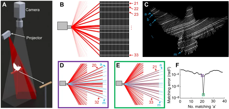
Fig. 1. We developed a new high-speed 3D surface reconstruction technique for rapidly locomoting animals based on binary spatially encoded structured light.(A) The 3D calibrated projection of a structured-light pattern on a flying bird is imaged by a high-speed camera. (B) The projected pattern is shown in black and white, while the color red is used to indicate the known lines and numbers of horizontally projected stripes (we show a side view of horizontal projection planes). Horizontal stripes are spaced unequally to ensure local uniqueness of the pattern, while vertical stripes are equally spaced for high spatial resolution. (C) The images captured by the camera with unknown horizontal stripes are labeled in blue. (D,E) Ordered but unidentified horizontal stripes (blue letters and lines) are matched with an ordered subset of known projection stripes (red numbers and lines). In D, the blue and red lines do not match, whereas in E they match. (F) Horizontal stripe matching error as a function of matching permutation, including the two boxed examples shown in D and E. The error is computed as the mean squared angle in radians between matching stripes. Note that the stripe numbering and lettering convention in this figure do not match the equations given in the text, they serve an illustrative purpose only.
Journal
of
Experimental
where Pc/p are 2D homogeneous camera or projector (c/p)
coordinates in pixels,Pware 3D coordinates,Kc/p is the internal
calibration matrix defined by Eqn 3 (with constantsα,β,u0andv0),
Ris the rotation matrix from the camera to the projector andTis the
translation matrix from the camera to the projector (where the optical center of the camera lies at the origin). While it was unknown to which projection plane each plane in the camera image corresponded, two equations could be written per camera plane based on the calibration above, Eqns 4 and 5. They were derived based on the principle that all the planes intersected at the optical center of the projector. Eqn 6 then followed from all vertical planes intersecting at a vector in space, while Eqn 7 is the equivalent for all horizontal planes.
akT½1 þbkT½2 þckT½3 ¼ 1; ð4Þ
dlT½1 þelT½2 þflT½3 ¼ 1; ð5Þ
akR½1;2 þbkR½2;2 þckR½3;2 ¼0; ð6Þ
dlR½1;1 þelR½2;1 þflR½3;1 ¼0: ð7Þ
Brackets used in Eqns 4–7 indicate the selection of a specific
[Row, Column] value in matrices.
For each intersection of horizontal plane, vertical plane and the bird,
the calibration was used to write Eqns 8 and 9, wherex,yandzdefined
the unknown 3D location of the intersection point. Further, we knew which two planes intersected at this point, so we wrote two more equations defining each plane (not shown). These four equations
combined into a single equation by eliminatingx,yandz(Eqn 10):
x¼ðxklacu0cÞz; ð8Þ
y¼ðyklbcv0cÞz; ð9Þ ðxklu0cÞ
ac ðakdlÞ þðy klv0cÞ
bc ðbkelÞ þ ðckflÞ ¼0: ð10Þ
With all known and unknown variables defined and constrained, known and unknown planes could be matched. This was done by
‘sliding’the unknown planes onto different known plane positions
to determine which position results in a minimal matching error, as
visualized in Fig. 1D–F. The mathematical analog to this combines
Eqns 4–7 and 10 into one large matrix as seen in Eqn 11:
MX¼B; ð11Þ
whereMandB are constant matrices andXcontains the
sought-after unit normal vectors for all ordered horizontal and vertical
unknown planes. BecauseXhas one degree of freedom, it can be
rewritten as:
X¼XpþpXh; ð12Þ
where Xp is a particular solution of X, Xh is the homogeneous
solution ofX, andpis a variable. The value ofpis critical as it
determines the particular solution ofXand can be tuned to slide the
unknown planes to different positions to reduce matching errors. Singular value decomposition was then used as defined in Eqn 13,
whereσare the singular values andUandVare square matrices, to
findXpin Eqn 14 andXh, which is the rightmost column ofV:
M¼Udiagðs1;s2; ;s3nÞVT; ð13Þ
Xp¼Vdiagð1=s1;1=s2; ;1=s3n1;0ÞUTB: ð14Þ
For each potential match between known and unknown planes, the error was computed as the mean squared angle between the
known and unknown planes. The correct matching sequence for the horizontal planes gave a much lower error than other possible matches due to the unequal spacing of the stripes. When the correct
matching planes were found for the horizontal planes, the value ofp
used in Eqn 12 was then used to match the vertical planes as well.
3D surface reconstruction and system accuracy
After the unknown planes were matched with the projected planes, 3D reconstruction of the surface was straightforward. For each stripe seen on the bird, its light plane was defined. Additionally, for each point at the center of a stripe, the 3D vector along which that point must lie was specified. The intersection of the vector and plane lies
on the bird’s surface. We then fit a surface (average 26,907 points)
to the point cloud of data (average 285 intersections and 11,405 total points) using the Gridfit toolbox in MATLAB (https://www. mathworks.com/matlabcentral/fileexchange/8998-surface-fitting-using-gridfit), which uses a modified ridge estimator with tunable smoothing. The result is shown in Fig. 2E for different wingbeat phases reconstructed with a single camera and projector.
The reconstruction accuracy achievable was estimated in a separate test with similar equipment settings. Using a sphere of known radius (22.23±0.05 mm, mean±s.d.), we found an accuracy of 0.31 mm (error) and precision of ±1.03 mm (s.d.) (see Fig. 2A, B). Errors were largest (double) in areas outside the calibration volume (the image corner regions). Additionally, occasional stripe mismatching occurred in the image processing steps, which accounts for other larger errors (Fig. S3). When processing both the sphere and bird, no manual manipulation was used and bird reconstruction was successful for 98% of the frames over four separate downstroke segments (two wingbeats of two flights).
Calculation of dorsal surface parameters
To calculate bird-specific surface parameters, a reference frame must be defined for each frame. To accomplish this automatically, we first identified the body of the bird by identifying surface points that move less than a preset threshold distance (see Fig. S2). To
compute thez-axis, the body points were fit to a plane, after which
thex-axis was computed by finding the line of symmetry of the body
points projected on that plane. To find a repeatable origin point, the
top of the bird’s head was found by fitting a paraboloid to points on
the head. For the frames we analyze here, the orientation of the axis did not change significantly and was thus set constant for all frames, while the origin point was fit linearly over all relevant frames. This computed body reference frame was labeled with subscript b. Another reference frame, the wing reference frame, was used for measuring wing shape and was labeled with subscript w. It was
found by rotating the body reference frame about thexb-axis in order
to best fit the (right) wing of the bird. The reference frames and the corresponding surfaces are shown in Fig. 3A,B.
Using these reference frames and the 3D data, surface metrics were computed. In Fig. 3D, the shape of the bird at its midline is tracked while in Fig. 3E,F, the shapes of dorsal airfoil slices of the wing are tracked at different spanwise positions. We determined the
angles of attack spanwise along the wing (see Fig. 3G–I) based on
these airfoils. The geometric angle of attack was found with a linear fit to each airfoil, while the induced angle of attack was found by computing the direction of the velocity of the wing from root to tip using the bird velocity and angular velocity of the wing. To reduce noise in these linear fits, outliers were detected using the RANSAC method (Fischler and Bolles, 1981). The effective angle of attack is the difference of the induced and geometric angles of attack.
Because of the angle of the bird’s wing relative to the camera
Journal
of
Experimental
and projector positions, angle of attack measurements beyond a spanwise position halfway to the wingtip are less reliable. This could be resolved in future setups by adding cameras and projectors to better image the wing under these angles.
RESULTS AND DISCUSSION
We quantified and analyzed the 3D wing and body shape of a flying bird during a portion of four downstrokes (41% to 65% on the first downstroke and 36% to 64% on the second downstroke after take-off ) using a novel high-speed, automated, 3D structured-light method. While our results are for a single projector and camera combination imaging the dorsal side of the bird, more cameras and projectors can be added to obtain full body volumetric reconstruction and provide a more complete analysis of wing morphing over an entire wingbeat cycle. In our analysis of the dorsal
data, we found that the bird’s tail rotates down significantly with
respect to the body (1720 deg s−1 in flight 1, 1550 deg s−1 in
flight 2) during the first downstroke after take-off (Fig. 3D) but not
the second (−290 deg s−1 in flight 1, 270 deg s−1 in flight 2)
(Fig. S3; all angular velocities are averaged over the downstroke phase analyzed). The wings rotate down at an average of
5700 deg s−1in this same portion of the downstroke. Further, the
wings are tracked at different spanwise positions (Fig. 3E,F), and we see that the wing twists relative to the body through the downstroke as confirmed by the geometric angle of attack plot (Fig. 3G). Using these data, we computed the effective aerodynamic angle of attack (Fig. 3I), which remains relatively constant between 50 and 70 deg in the first downstroke and 45 and 60 deg in the second downstroke (Fig. S3C,F). These high angles during the downstroke at take-off enable the bird to support its body weight with both lift and drag, while simultaneously generating significant thrust by tilting lift forward. This is facilitated by the close to horizontal orientation of the wing surface moving predominantly downward (Fig. 3A,B) combined with the high lift and drag coefficients of a bird wing at
Δt=2.5 ms
C
E
A
B
D
Camera Projector Error (mm)
–2 0 2
Error (mm)
0 0.5
1.5
1
0.5 0
–0.5
–1
[image:4.612.49.356.54.531.2]–1.5 1
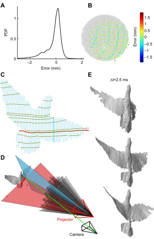
Fig. 2. Single-shot 3D surface reconstruction accuracy and results.(A,B) Method verification tests using a 22.23±0.05 mm (mean±s.d.) radius sphere results in a reconstruction error of 0.31±1.03 mm averaged over sphere location for 400 frames, showing the new method is both accurate and precise. In A, the probability density function (PDF) of the error in the measured radius is shown. (C) To reconstruct a surface, horizontal and vertical stripes are separated using image processing techniques (Fig. S1). Next, all intersections of these stripes are calculated (one example is shown as a green dot). (D) Each stripe seen in the camera represents a 3D projected plane of light and each 2D intersection point represents a vector in 3D space on which the 3D intersection on the bird’s surface lies. A sampling of projection planes is shown in black, while single horizontal and vertical planes are extended along with their intersection point on the bird’s surfaces. Color coding corresponds to Fig. 2C. (E) 3D surface
reconstruction of the flapping wing (and body) of a bird in flight at 2.5 ms intervals (33, 44 and 55% of its first downstroke after take-off ).
Journal
of
Experimental
these high angles of attack (Kruyt et al., 2014). The measurements illustrate how the system provides insight into how birds morph their wings to generate aerodynamic forces, and could give insight into maneuvering flight in future studies.
Beyond studying birds, this new structured-light method has many benefits for capturing 3D data in experimental biology and engineering. It is automated to allow for a high throughput of data, single-shot to track deforming objects, binary to allow for high-speed tracking, and uses a single color to allow for multiple view angles. While the current application of this technique is for studying bird flight, it is broadly adaptable for tracking shapes of other dynamically morphing animals, plants and objects of interest.
Acknowledgements
We thank J. W. Kruyt for initially helping us develop and test temporally encoded structured-light methods, and A. K. Stowers for reviewing the mathematics.
Competing interests
The authors declare no competing or financial interests.
Author contributions
Conceptualization and writing–review and editing: M.E.D., D.L., A.A.B.; Methodology: M.A.D., D.L.; Software, validation, formal analysis, investigation, data curation, writing–original draft preparation, and visualization: M.E.D.; Resources and project administration: D.L., A.A.B.; Supervision: D.L.
Funding
This research was supported by the National Science Foundation (NSF) Graduate Research Fellowship under grant no. DGE-114747 to M.E.D.; NSF grant IOS-0744056 to A.A.B.; and Office of Naval Research MURI grant N00014-10-1-0951, the Micro Autonomous Systems and Technology at the Army Research Laboratory–
Collaborative Technology Alliance Center grant MCE-16-17-4.3, and NSF CAREER Award 1552419 to D.L.
Supplementary information
Supplementary information available online at
http://jeb.biologists.org/lookup/doi/10.1242/jeb.149708.supplemental
I
H
G
F
E
D
B
A
C
yb yb
zb xb=x zb
w
xb=xw
D
F E
D
F E
zb
(mm)
xb (mm)
zw
(mm)
xw (mm) xw (mm)
zw
(mm)
Downstroke (%)
0 41 100
Tail
r/R
αgeo
(deg)
αind
(deg)
r/R r/R
r r
E F
yw
yw
zw zw
E F E F
-αgeo -αind
αeff
zw
xw
v
65
r0 r0
αeff
(deg)
–100
–100 –80 –60 –40 –20 –40 –20 0 20
–20 –10
0 0
10
–20 –10 10
0
–100 –80 –60 –40 –20 0
0 20 40 60 80 100 –80 –60
0 0.2 0.4 0.6 0.8 1 0 0.2 0.4 0.6 0.8 1 0 0.2 0.4 0.6 0.8 1
[image:5.612.67.545.58.443.2]–40 –20 0 –60 –40 –20 0 –60 –40 –20 0
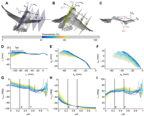
Fig. 3. The dorsal wing profile, twist and aerodynamic angle of attack of a bird is automatically tracked throughout a section of the downstroke for which the wing is fully in view.(A,B) 3D upper surface of a parrotlet at 41 and 65% of its first downstroke after take-off, respectively. Two reference frames are defined as a function of time: a translating body reference frame (subscript b) withzbpointing up andxbpointing forward, and a translating and rotating wing reference frame (subscript w). The origin for both reference frames is the top of the head. The wing reference frame is rotated aboutxbso it is parallel with the right wing. Ther-axis is parallel toywand begins at the plane labeledr0, which intersects the bird’s right shoulder. (C) Side view of bird shown in A, illustrating the definition of geometric, induced and effective angle of attack. (D) The shape of the bird at the centerline of its dorsal surface (yb=0), where the purple line corresponds to A and the yellow line corresponds to B. (E,F) The dorsal profile shape of the bird wing as a function of wing radius,r, equal to 0.25Rand 0.50R, whereRis the length of the right wing from the planer0to the wingtip and is held constant across all frames. The valueris equal to zero at the plane labeledr0. (G) The geometric angle of attack (twist) of the wing with respect to the body of the bird is approximately linear. (H) Induced angle of attack of the wing due to bird forward and wing flapping velocity based on the average spanwise velocity of center of the wing. (I) Effective angle of attack calculated as the geometric angle of attack minus the induced angle of attack.
Journal
of
Experimental
References
Ackerman, J. D., Keller, K. and Fuchs, H.(2002). Surface reconstruction of
abdominal organs using laparoscopic structured light for augmented reality.
Three-Dimensional Image Capture Appl.4661, 39-46.
Biesel, W., Butz, H. and Nachtigall, W. (1985). Erste messungen der
flogelgeometrie bei frei gleitflie-genden haustauben (Columba livia var.
domestica) unter benutzung neu ausgearbeiteter verfahren der
windkanal-technik und der stereophotogrammetrie.Biona-Report3 3, 138-160.
Carruthers, A. C., Walker, S. M., Thomas, A. L. R. and Taylor, G. K.(2010).
Aerodynamics of aerofoil sections measured on a free-flying bird. Proc. Inst.
Mech. Eng. Part G J. Aerosp. Eng.224, 855-864.
Cheney, J. A., Konow, N., Middleton, K. M., Breuer, K. S., Roberts, T. J., Giblin,
E. L. and Swartz, S. M.(2014). Membrane muscle function in the compliant
wings of bats.Bioinspir. Biomim.9, 025007.
Combes, S. A. and Daniel, T. L.(2003). Into thin air: contributions of aerodynamic
and inertial-elastic forces to wing bending in the hawkmothManduca sexta.
J. Exp. Biol.206, 2999-3006.
Fischler, M. A. and Bolles, R. C.(1981). Random sample consensus: a paradigm
for model fitting with applicatlons to image analysis and automated cartography.
Commun. ACM24, 381-395.
Fontaine, E. I., Zabala, F., Dickinson, M. H. and Burdick, J. W.(2009). Wing and
body motion during flight initiation in Drosophila revealed by automated visual tracking.J. Exp. Biol.212, 1307-1323.
Guan, C., Hassebrook, L. G. and Lau, D. L.(2003). Composite structured light
pattern for three-dimensional video.Opt. Express11, 406-417.
Hedrick, T. L.(2008). Software techniques for two- and three-dimensional kinematic
measurements of biological and biomimetic systems.Bioinspir. Biomim.3, 34001.
Hedrick, T. L., Tobalske, B. W. and Biewener, A. A.(2002). Estimates of circulation
and gait change based on a three-dimensional kinematic analysis of flight in cockatiels (Nymphicus hollandicus) and ringed turtle-doves (Streptopelia risoria).
J. Exp. Biol.205, 1389-1409.
Kawasaki, H., Furukawa, R., Sagawa, R. and Yagi, Y.(2008). Dynamic scene
shape reconstruction using a single structured light pattern. InIEEE 2nd Joint
3DIM/3DPVT Conference on Computer Vision and Pattern Recognition,
Vols 1-12, pp. 2806-2813.
Kruyt, J. W., Quicazán-Rubio, E. M., van Heijst, G. F., Altshuler, D. L. and
Lentink, D.(2014). Hummingbird wing efficacy depends on aspect ratio and
compares with helicopter rotors.J. R. Soc. Interface11, 570-581.
Lenar, J., Witkowski, M., Carbone, V., Kolk, S., Adamczyk, M., Sitnik, R., van der
Krogt, M. and Verdonschot, N.(2013). Lower body kinematics evaluation based
on a multidirectional four-dimensional structured light measurement.J. Biomed. Opt.18, 056014.
Lohry, W. and Zhang, S.(2014). High-speed absolute three-dimensional shape
measurement using three binary dithered patterns.Opt. Express22, 26752.
McKeon, R. T. and Flynn, P. J.(2010). Three-dimensional facial imaging using a
static light screen (SLS) and a dynamic subject.IEEE Trans. Instrum. Meas.59, 774-783.
Muijres, F. T., Elzinga, M. J., Melis, J. M. and Dickinson, M. H.(2014). Flies evade
looming targets by executing rapid visually directed banked turns.Science344, 172-177.
Pennycuick, C. J.(2008).Modeling the Flying Bird. Burlington, MA: Academic
Press.
Ristroph, L., Berman, G. J., Bergou, A. J., Wang, Z. J. and Cohen, I.(2009).
Automated hull reconstruction motion tracking (HRMT) applied to sideways maneuvers of free-flying insects.J. Exp. Biol.212, 1324-1335.
Ros, I. G., Badger, M. A., Pierson, A. N., Bassman, L. C. and Biewener, A. A. (2015). Pigeons produce aerodynamic torques through changes in wing trajectory during low speed aerial turns.J. Exp. Biol.218, 480-490.
Saberioon, M. M. and Cisar, P.(2016). Automated multiple fish tracking in
three-dimension using a structured light sensor.Comput. Electron. Agric.121, 215-221. Sagawa, R., Sakashita, K., Kasuya, N., Kawasaki, H., Furukawa, R. and Yagi, Y. (2012). Grid-based active stereo with single-colored wave pattern for dense one-shot 3D scan. InIEEE International Conference on 3D Imaging, Modeling,
Processing, Visualization and Transmission,pp. 363-370.
Salvi, J., Fernandez, S., Pribanic, T. and Llado, X.(2010). A state of the art in
structured light patterns for surface profilometry.Pattern Recognit.43, 2666-2680.
Sarbolandi, H., Lefloch, D. and Kolb, A.(2015). Kinect range sensing:
structured-light versus time-of-fstructured-light kinect.Comput. Vis. Image Underst.139, 1-20.
Su, W.-H. and Liu, H.(2006). Calibration-based two-frequency projected fringe
profilometry: a robust, accurate, and single-shot measurement for objects with large depth discontinuities.Opt. Express14, 9178-9187.
Tobalske, B. W., Warrick, D. R., Clark, C. J., Powers, D. R., Hedrick, T. L., Hyder,
G. A. and Biewener, A. A.(2007). Three-dimensional kinematics of hummingbird
flight.J. Exp. Biol.210, 2368-2382.
Walker, S. M., Thomas, A. L. R. and Taylor, G. K.(2009). Deformable wing
kinematics in the desert locust: how and why do camber, twist and topography vary through the stroke?J. R. Soc. Interface6, 735-747.
Wang, Y., Laughner, J. I., Efimov, I. R. and Zhang, S.(2013). 3D absolute shape
measurement of live rabbit hearts with a superfast two-frequency phase-shifting technique.Opt. Express21, 6631-6636.
Williams, C. D. and Biewener, A. A.(2015). Pigeons trade efficiency for stability in
response to level of challenge during confined flight.Proc. Natl. Acad. Sci. USA 2015, 201407298.
Wolf, T. and Konrath, R.(2015). Avian wing geometry and kinematics of a
free-flying barn owl in flapping flight.Exp. Fluids56, 28.
Wootton, R. J.(1992). Functional morphology of insect wings.Entomol113-140.
Zhang, Z. H.(2012). Review of single-shot 3D shape measurement by phase
calculation-based fringe projection techniques.Opt. Lasers Eng.50, 1097-1106.
Zhang, G., Sun, J., Chen, D. and Wang, Y.(2008). Flapping motion measurement
of honeybee bilateral wings using four virtual structured-light sensors.Sensors
Actuators A Phys.148, 19-27.