Music Tel-240 Installation and
Operation Manual
Version 3.0 Release 2 June 2002
MusicTel 240
Installation and Operation Manual
NOTICE
This publication refers to the Music Tel - 240 Music on Hold System Release 3.
Additional copies of this manual may be obtained from Aleen Technologies of this manual or parts thereof without written permission from Aleen Technologies is strictly prohibited.
Aleen Technologies reserves the right to modify the hardware and software described in the manual without prior notice. However, changes made to the hardware or software described do not necessarily render this publication invalid.
WARRANTY
In the event that the product proves to be defective in workmanship or materials within a period of one year from date of shipment, Aleen Technologies shall repair or replace the product at its discretion. Transportation will be the responsibility of the
dealer/distributor.
Under no circumstances shall Aleen Technologies be liable for consequential or special damages, loss of revenue or user/dealer expenses arising out of or in connection with the use or performance of the product, whether based on contract, tort, or any other legal agreement.
The following shall void the above warranty: malfunctions resulting from fire, accident, neglect, abuse, or acts of God; use of improper electrical power; or repair of, tampering with or alteration of the product by anyone other than Aleen Technologies authorized personnel.
MusicTel-240 Installation and Operation Manual a
TABLE OF CONTENTS
1. INTRODUCTION ... 1-1 2. DESCRIPTION ... 2-1 2.1 Physical Description ... 2-1 2.1.1 Front Panel...2-2
2.2 Unpacking... 2-3 2.2.1 Inserting the Memory Module ...2-4
2.2.2 Physical Installation...2-5 3. INSTALLATION AND OPERATION ... 3-1 3.1 Recording on a Music Channel... 3-2 3.2 Erasing the Content of the Music Channels... 3-4 3.2.1 Erasing the Contents of a Single Channel...3-4 3.2.2 Erasing the Contents of All Music Channels ...3-5 3.3 Listening to the Content of a Music Channel ... 3-6 3.4 Configuring the Music Playlist ... 3-7 3.5 Music-On-Hold Playback Level ... 3-7 4. SPECIFICATIONS ... 4-1 4.1 Recording Cable ... 4-1 4.2 Audio Cable... 4-2 4.3 Jumpers Configuration... 4-3 4.4 Technical Specifications ... 4-5
MusicTel-240 Installation and Operating Manual 1-1
1. INTRODUCTION
The MusicTel-240 is a digital music on hold player. It is built with absolutely no mechanically-moving parts. The MusicTel-240 allows 9 minutes of stored music, in a non-volatile, replaceable memory module. Recording is performed by connecting the MusicTel-240 to an external audio device.
Figure 1-1. General View
Introduction
1-2 MusicTel-240 Installation and Operating Manual
The MusicTel-240 has the following features:
• Four music channels.
• Automatic time allocation – 9 minutes of music on a single channel.
• Replaceable memory card .
• High audio quality.
• Zero gap recording – silence is not recorded.
• Simple and convenient operation.
• Built-in speaker for monitoring music channel content.
• Support of 8Ω/600Ω Output Impedance.
MusicTel-240 Installation and Operation Manual 2-1
2. DESCRIPTION
2.1 Physical Description
The functional components of the MusicTel-240 are located on its front panel.
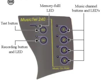
The LEDs and buttons are located on the top panel. The MusicTel-240 incorporates four music channel status LEDs and configuration keys, a “ ” button, and a “ ” button.
Figure 2-1. Top Panel
rec test
Description
2-2 MusicTel-240 Installation and Operation Manual The four music channels LEDs on the top panel indicate that a corresponding music channel is included in the play list. For example: if music channels 2 and 4 are set to be on the play list, then LEDs “2” and “4” are lit.
The “Mem Full” LED displays the status of the memory module while recording. A flashing LED indicates that the memory module is 90% full. At 95% the LED flashes at a faster rate. A constantly lit LED indicates that the memory module is 100% full, and the recording will stop.
MusicTel-240 is operated via the top panel keys as described in section 3 of this manual.
2.1.1 Front Panel
The front panel incorporates the power supply and the audio input/output jack connectors, the volume level adjustment potentiometer, and the memory module compartment (slot).
RJ-11
In / Out 9VDC Volume Level Adjustment Potentiometer
Memory Module Compartment
Figure 2-2. Front Panel
Description
MusicTel-240 Installation and Operation Manual 2-3
2.2 Unpacking
The MusicTel-240 installation package should contain the following items:
• MusicTel-240 unit.
• DC power supply.
• Flash memory module.
• Standard RJ-11 audio cable.
• Recording cable.
• Installation and operating manual.
• Wall mounting installation screws, and a drill template.
If any of these components are damaged or missing, please contact your local ITS dealer.
Description
2-4 MusicTel-240 Installation and Operation Manual 2.2.1 Inserting the Memory Module
The flash memory module is inserted into the designated compartment, located on the front panel of the MusicTel-240.
* NOTE: “9 min. Release 3” should be written on the memory card.
To insert the memory module:
1. Disconnect the MusicTel-240 from the mains.
2. Carefully insert the module into its designated compartment (see fig. 2-3).
3. Push the memory module until it is aligned with the MusicTel-240 casing (see fig.2-3).
Figure 2-3. Inserting Memory Module
Description
MusicTel-240 Installation and Operation Manual 2-5
2.2.2 Physical Installation
The MusicTel-240 is delivered with pre-recorded music. New music can be recorded before installing the MusicTel-240 on the wall, and before connecting it to the PBX.
To install the MusicTel-240:
1. Use a drill and the wall plugs to place the two screws, and mount the MusicTel-240 close to the PBX
2. Plug the 9VDC adapter jack into the MusicTel-240 power supply connector, and connect the 9VDC adapter to the mains. The device performs a test routine, checking all music channels and LEDs. When completed, the LED of channel 1 is lit.
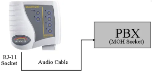
3. Connect the audio cable to the MusicTel-240 and to the MoH (Music on Hold) jack in the PBX, as described in Figure 2-4 below.
4. Select the channels to be played as the music on-hold, if any were recorded (see para.3-4).
Figure 2-4. Connecting the Audio Cable
3-1 MusicTel-240 Installation and Operation Manual
3. INSTALLATION AND OPERATION
This section describes the operating features of the MusicTel-240.
The following operating features are available and described:
• Recording a music channel.
• Erasing the contents of the music channels.
• Listening to the contents of a music channel.
• Configuring the music playlist.
• Setting the MusicTel-240 volume levels.
Note : New device includes four recorded audio fragments .
Installation and Operation
MusicTel-240 Installation and Operation Manual 3-2
3.1 Recording on a Music Channel
To record music on the MusicTel-240, a special recording cable is used (provided). Recording new music can only be performed on an empty channel, provided the memory is not full. Erasing instructions are given in section 3.2 of this manual.
Note: make sure the Memory Module is properly inserted into the MusicTel-240.
1. Plug the 9VDC adapter jack into the MusicTel-240 power supply connector.
Next, connect the 9VDC adapter to the mains.
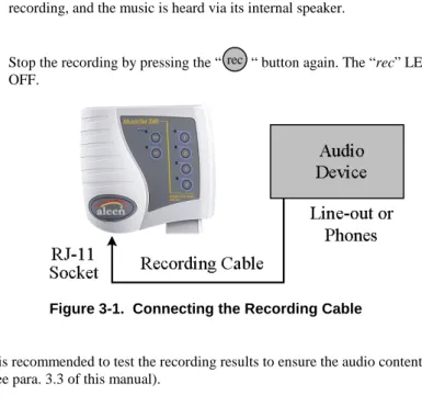
2. Connect the recording cable to the RJ-11 socket on the front panel of the MusicTel-240 (see Figure 2-2). The device is automatically switched to Recording Mode. Next, connect the other end of the Recording Cable to the music source device (CD player, tape etc.), as described in Figure 3-1.
Once the Recording Cable is inserted, the LED of channel 1 is lit. A flashing LED indicates the selected channel is not recorded, while a constantly lit LED indicates the selected channel is recorded.
3. Select a channel to be recorded by pressing its button. The LED of the selected channel will start flashing.
4. Press the “ ” button on the top panel of the MusicTel-240. The “rec” LED and the selected channel’s LED are lit.
rec
Installation and Operation
3-3 MusicTel-240 Installation and Operation Manual 5. Press the “Play” button on the audio device. The MusicTel-240 starts
recording, and the music is heard via its internal speaker.
6. Stop the recording by pressing the “ “ button again. The “rec” LED turns OFF.
Figure 3-1. Connecting the Recording Cable
It is recommended to test the recording results to ensure the audio content (see para. 3.3 of this manual).
rec
Installation and Operation
MusicTel-240 Installation and Operation Manual 3-4
3.2 Erasing the Content of the Music Channels
Two erasing types are available:
1. Erasing the contents of a single channel.
2. Erasing the contents of all music channels.
These options are described below.
Note: All Erase operations require the connection of the Recording Cable to the MusicTel-240.
3.2.1 Erasing the Contents of a Single Channel
1. Connect the recording cable (provided) to the MusicTel-240.
2. Select the channel to erase by pressing the respective button. The selected channel’s LED is lit.
3. Press the “ “ button and the respective channel’s button simultaneously.
A flashing “rec” LED indicates that the MusicTel-240 is still performing an Erase procedure.
4. At the end of the erasing process, the LED of the erased channel will start flashing.
Note: The Erase procedure can take a few seconds to complete while the device re-organizes its memory structure.
rec
Installation and Operation
3-5 MusicTel-240 Installation and Operation Manual 3.2.2 Erasing the Contents of All Music Channels
1. Connect the recording cable (provided) to the MusicTel-240. A flashing channel LED indicates that the channel is not recorded, while a constantly lit channel LED indicates that the channel is recorded.
2. Press the “ ” and the “ “ buttons simultaneously.
At the end of this process, the LED of channel 1 starts flashing, indicating the unit is ready for recording.
Note: The Erase procedure can take a few seconds to complete while the device re-organizes its memory structure.
rec test
Installation and Operation
MusicTel-240 Installation and Operation Manual 3-6
3.3 Listening to the Content of a Music Channel
Note: It is recommended to disconnect the recording cable while performing the test.
To test the recorded music channel content:
1. Select the music channel by pressing the respective button. Make sure that the respective LED is lit. One or more channels can be selected.
2. Press the “ ” button on the top panel of the MusicTel-240.
3. The selected music channel contents will be heard via the internal speaker, while its LED is flashing. If the recording cable is left connected, it cancels the flashing LED, and the channel indication is not displayed.
If more than one channel is selected, then the selected channels will be played in ascending order.
4. Stop the playback by pressing the “ “ button again.
test
test
Installation and Operation
3-7 MusicTel-240 Installation and Operation Manual
3.4 Configuring the Music Playlist
To configure the music playlist:
1. Disconnect the recording cable from the MusicTel-240.
2. Select the music channels to be added to the playlist by pressing their respective button.
3. Make sure that the respective LEDs of the selected music channels are lit.
4. To remove a music channel from the playlist, press the selected music channel’s button again until its LED is turned off.
3.5 Music-On-Hold Playback Level
Note: The volume level which is heard while testing the recording via the internal speaker, is not an indication of the audio levels heard via the PBX.
MoH (Music on Hold) playback level must be tested to ensure it is recorded at adequate levels.
Installation and Operation
MusicTel-240 Installation and Operation Manual 3-8
To test MoH volume levels:
1. Connect the MusicTel-240 to the PBX, as described in par. 2.2.2 of this manual.
2. Call the PBX from an external line and answer the call from the PBX.
3. Put the call on ‘Hold’. The Music on Hold should now be heard.
4. Adjust the music volume level by adjusting the volume level potentiometer, located on the front panel of the MusicTel-240 (see Figure 2-2).
5. End the call.
4-1 MusicTel-240 Installation and Operation Manual
4. SPECIFICATIONS 4.1 Recording Cable
RJ-11 pins 1,2 – Audio In.
The audio cable is connected to the P.L. plug, which connects to the music source device (CD player etc).
RJ-11 pin 5,6 – Short-Circuited.
The short-circuit is applied at the P.L. end of the recording cable (see Figure 4-1).
RJ 11 (MusicTel-240)
SHORT
AUDIO 1
2 3 4 5 6
P.L. Jack
Figure 4-1. Recording Cable
Specifications
MusicTel-240 Installation and Operation Manual 4-2
4.2 Audio Cable
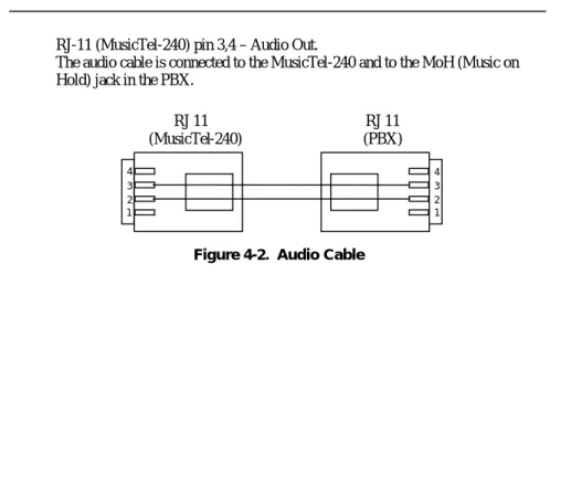
RJ-11 (MusicTel-240) pin 3,4 – Audio Out.
The audio cable is connected to the MusicTel-240 and to the MoH (Music on Hold) jack in the PBX.
RJ 11 (MusicTel-240)
1 2 3 4
1 2 3 4
RJ 11 (PBX)
Figure 4-2. Audio Cable
Specifications
4-3 MusicTel-240 Installation and Operation Manual
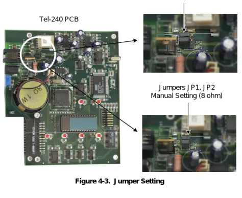
4.3 Jumpers Configuration
By default, the MusicTel-240 Output Impedance is configured to 600Ω. Some PBX types require the MusicTel-240 Output Impedance to be configured to 8Ω (please refer to your PBX Specifications).
To configure the MusicTel-240 Output Impedance:
1. Disconnect the MusicTel-240 from the mains.
2. Remove the four screws on the bottom panel of the MusicTel-240.
Carefully remove the cover.
3. Remove the Jumpers from JP1 and JP2 (see Fig. 4-3).
4. Replace the two Jumpers so each cover both Jumper Pins (see Fig. 4-3).
The Output Impedance is now configured to 8Ω. 5. Carefully replace the unit’s cover.
6. Insert the four screws on the bottom panel.
Specifications
MusicTel-240 Installation and Operation Manual 4-4 Jumpers JP1, JP2
Default Setting (600 ohm)
Jumpers JP1, JP2 Manual Setting (8 ohm) Tel-240 PCB
Figure 4-3. Jumper Setting
Specifications
4-5 MusicTel-240 Installation and Operation Manual
4.4 Technical Specifications
DC Power Source (included) Input: 220VAC/50Hz.
(optional: 110VAC/60Hz) Output: 9VDC / 800mA.
CODEC Rate 64kBps PCM
Recording Time 9 min.
Output Impedance 8Ω / 600Ω
Weight 750gr. (Boxed)
Aleen Technologies
Website: www.aleentech.com E-mail: [email protected]