Reconstruction Parameters of Local Scattering Sources of
a Metallic Strip from the Backscattering Pattern
Stanislav N. Kutishchev
Department of Physics and Chemistry, Voronezh State University of Architecture and Civil Engineering, Voronezh, Russia. Email: [email protected]
Received October 11th, 2012; revised November 13th, 2012; accepted November 23rd, 2012
ABSTRACT
In this paper, it is proved the ability of quantity reconstruction, amplitudes and coordinates of metallic strip local scat- tering sources from the backscattering pattern. They are performed as the results of numerical solution for the infinite perfect conducting strip in case of E-polarization of the incident plane electromagnetic wave. In this case it is necessary to fulfill the following conditions. The local sources amplitudes should be the same order, in transverse and longitudinal directions the local sources should be separated into distances more than apparatus resolution, and the object maximum size does not have to be more than approximately 50λ. It was shown the limit and ability of the further development of the offered method.
Keywords: Backscattering Pattern; Local Scattering Sources; Radar Image; Electromagnetic Wave; Method; Metallic Strip
1. Introduction
Nowadays the researches of creating of objects scattering structure reconstruction methods in scattering field in radiolocation [1-7], antenna theory [8], radio astronomy [9], optics [10] and other scientific regions are being done. Urgency of radiolocation work in this region is brought about, for example, the essential of getting rather full in- formation about space structure of local scattering sources [11] on the surface of complex shape objects with the pur- pose of improving means and methods of the objects radar visibility decreasing.
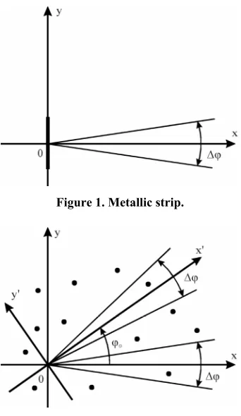
Doing radiolocation characteristic research of objects at ranges and in laboratories the scattering pattern is built as a result of the object turning. So reconstruction problem of local scattering sources of this object appears from the backscattering pattern. For the object model [12] as the system of isotropic rigidly tied and electrodynamically independent scatters in work [7] the method of numerical solution of the problems was offered. It is interesting to use this method for the solution of analyzing problem in case of the infinite (along z axis) perfect conducting strip (Figure 1). The strip is believed to be infinitely thin.
Work aim is the researching of the reconstruction abi- lity of parameters (quantity, amplitudes and coordinates) of metallic strip scattering sources from the backscattering pattern.
The reconstruction ability of the parameters of the me- tallic cylindrical object (metallic strip) local scattering
sources has been first investigated in the paper. The solu- tion of the inverse electrodynamical problem is based on apriori assumption about discretion of local sources the cylindrical object (the model of isotropic rigidly tied and electrodynamically independent scatters). The dependences of the reconstructed amplitudes and transverse coordi- nates of two local sources of the metallic strip on the aspect angle (the case of a monostatic scattering) have been first numerically obtained. As the result of analysis of the obtained numerical data it was found that the ab- solute error of the reconstruction of the transverse coor-dinates of the local sources does not exceed approxi- mately 0.03λ. The limits of the offered method were esti- mated.
2. Method of Reconstruction
Let’s look at the case of a monostatic scattering of the plane electromagnetic wave from the system of N iso- tropic rigidly tied and electrodynamically independent scatters (Figure 2) which is the electrodynamical model [12] of the object. Receiving narrow-band reflected signal in the far zone of the object and transmit-receive antenna the backscattering pattern including the results of work [2] and the problem geometry (believing that measurements are done in xy-plane) can be performed as:
0
1
exp 2 cos sin N
i i i
i
E E j k x y
Figure 1. Metallic strip.
Figure 2. Object model.
where xm, ym are the coordinates of m-scatter; m is the amplitude of the signal scattering from m-scatter; φ is the observation angle calculated from x-axis directed along bisector of angles Δφ;
E
2π
k is the wave number; λ is the wavelength. Formula (1) is right for every observation angles φ.
When 2=1 formula (1) can be linearized and
changed as:
0
1
exp 2 , sin 2 N
i i
i
E u E j y u u k k
% = , (2)where E%n Enexp 2
j kxn
, u k sin
—spatial fre- quency.So this problem can be expressed as: for observing ob- ject model is necessary to find the number of local scat- tering sources N, their amplitudes iand their transversal and longitudinal coordinates i and i
E
y x according to the known from experiment backscattering pattern , where
0
E u
sin 2
u k =k.
The method of the solution of the considered problem consists of some stages [7].
Stage 1. From fragmentE 0
, which is known at2 1
= , quantity of local sources N, their trans- verse coordinates iand amplitudes are found. Namely, spatial frequency spectrum
y
,
E u
is found out from the fragment known from measurements backscattering pattern of the object E(0)
(1):
,
0
, sin
2
0, sin 2 .
E u u k k
E u u k , (3)
Writing the spatial frequency spectrum E u
,
in (3) a rectangular window [13] is used, legal using of which is connected with the small value of observation angles sector Δφ.Using spatial frequency spectrum E u
,
one-di- mensional radar image J y
,
of the object [3-7,14] is found:
1 1, , exp
2π
sin 2
2 ,
2π 2
2 i N i i i d
J y E u jyu
k y y
k E k y y
u (4)From this formula it is known that the number of main maxima equals to the number of local sources N. The transversal coordinates of the local sources equal a half of the transverse ones going with main maxima. The values of the main maxima of the one-dimensional radar image
,
J y (4) correspond to the amplitudes of the object local sources. i
E
Stage 2. Using the fragment E 0
which is known at 0 2=1, with algorithm help of the 1st stage the transverse coordinates i of the local sources in x'y' coordinates system turned to the angle 0y
with respect to xy coordinates system (Figure 2) are calculated.
Let us look at the backscattering pattern E 0
in the aspect angles sector 0 21 (Figure 2). Using the well-known relations [15] for the coordinate transformation of the local scattering sources let us write it in x'y' coordinates system as [4]:
0 0 0 1 0exp 2 cos sin ,
2 1. N
i i i
i
E
E j k x y
(5)In this situation 0 can take any values.
From the match up (5) and (1) it is summed that the algorithm of calculation of the transverse coordinates yi of the second stage is analogous to the algorithm of cal- culation of the transverse coordinates of the first
stage. i
y
From the resulting local sources transverse coordinates ,
i i
y y their longitudinal ones are calculated (Figure
2) [4]: i
y
0
ctg 1, ,
i i
ordinates decreases. For 0 90ο
i i
x y. (7) In this case the error of the reconstruction of the longi- tudinal coordinates in xy system equals to the error of the reconstruction of the transverse coordinates in x'y' system. So at the second stage it is better to choose 0 90ο.
3. Numerical Results and Discussion
Later there are the results of the solution of the observing problem for the metallic strip with the lower edge co- ordinates (0, −5λ) and upper edge coordinates (0, 5λ) (Figure 1). The backscattering pattern of the strip was calculated by the rigorous method of the integral equa- tions [16] in case of E-polarization (E is directed along z axis) of the incident plane monochromatic electromag- netic wave with the amplitude equals 30.
In Figure 3 the dependences of the reconstructed trans- verse coordinates of two local sources of the strip on the aspect angle φ are shown. The value of the aspect angles sector ∆φ = 12˚. In this case two local sources starting with φ0 = 6˚ are reconstructed when the normal angle to the strip surface is not thrown into the aspect angles sector (φ0 = 0˚). Curves 1 and 2, Figure 3 practically equal, so the first local source is located on the lower edge of the strip. For the aspect angles φ0 > 48˚ the amplitude of the first local source is extremely small (Figure 4) and this local source is not reconstructed. Curves 3 and 4, Figure 3 practically match, so the second local source is located on the strip upper edge for the aspect angles (6˚, 90˚). The local scattering sources of the strip are located on its sur- face, so the reconstruction of its longitudinal coordinates is obvious.
In Figure 4 the dependences of reconstructed ampli- tudes of two local sources of the strip are shown on the
Figure 3. The dependence of the reconstructed transverse coordinates of two local sources of the strip on the aspect angle φ0 (1) The reconstructed coordinates of the first local source; (2) Coordinates of the strip lower edge; (3) The re- constructed coordinates of the second local source; (4) Co- ordinates of the strip upper edge.
Figure 4. The dependence of the reconstructed amplitudes of two local sources of the strip on the aspect angle φ0. (1) The first local source; (2) The second local source.
aspect angle φ0. Their amplitudes are practically equal for small aspect angles. Increasing the observation angle φ0 the amplitude of the second local source starts over the amplitude of the first local source. For the aspect angles φ0 > 48˚ the amplitude of the first local source becomes negligibly small, as the amplitude of the second one at φ0 = 90˚ equals 4.67.
Further as an illustration the results of reconstruction of the local sources of this metallic strip for case ∆φ = 12˚ and φ0= 28˚ are shown.
The curve Figure 5 is a fragment of the amplitude backscattering pattern E u
of the strip in spatial fre-quency sector u [k sin(22˚); k sin(34˚)], (∆φ = 12˚, φ0 = 28˚).The curve Figure 6 is a fragment of the phase back- scattering pattern arg
u (let us notice that
ex
E u E u p jarg u ) of the strip in spatial fre- quency sector u [k sin(22˚); k sin(34˚)] (∆φ = 12˚, φ0= 28˚).
In Figure 7 the modulus of the one-dimensional image of the strip J for u [k sin(22˚); k sin(34˚)] (∆φ = 12˚,
φ0= 28˚) is shown. Two main maxima correspond to two local sources (N = 2). The reconstructed transverse coor- dinates of the local sources r (Table 1) equal to a half of transverse coordinates of the corresponding main maxi- ma. The transverse coordinates y' (Table 1) correspond to the transverse coordinates of the strip edges. The modulus values of the main maxima of the one-dimensional image
y
,
J y correspond to the modulus of the recon- structed amplitudes of the local sources Er (Table 1).
Figure 5. The amplitude backscattering pattern of the strip in spatial frequencies sector u [k sin(22˚); k sin(34˚)] (∆φ
[image:4.595.58.288.290.426.2]= 12˚, φ0= 28˚).
Figure 6. The phase backscattering pattern of the strip in spatial frequencies sector u [k sin(22˚); k sin(34˚)] (∆φ = 12˚, φ0 = 28˚).
Figure 7. The modulus of the one-dimensional image J of the strip for u [k sin(22˚); k sin(34˚)] (∆φ = 12˚, φ0 = 28˚).
Table 1. Data of the strip local scattering sources.
i y' yr Er
1 −4.42λ −4.45λ 2.74
2 4.42λ 4.45λ 7.35
4. Conclusions
As a result, this method allows us to reconstruct from backscattering pattern the parameters (quantity, ampli- tudes and coordinates) of isotropic stiff-tied and electro- dynamically independent local scattering sources of a me- tallic strip. In this case it is necessary to fulfill the fol- lowing conditions. The local sources amplitudes should be the same order, in transverse and longitudinal directions the local sources should be separated into distances more than resolution
2
, and the object maximum size does not have to be more than approximately 50λ.Further it is planned to use this method for the recon- struction of the local scattering sources of two-dimen- sional cavities of a complex shape.
REFERENCES
[1] A. A. Luchin, “Methods of Approximate Solution of the Inverse Problem in Radiolocation,” Zarubezhnaya Radio- elektronika. Uspekhi Sovremennoy Radioelektroniki, No. 8, 1999, pp. 30-44.
[2] I. Y. Gatilova, V. A. Pon’kin and T. S. Uzhakhov, “De- termination of the Spatial Structure of Local Reflectors on the Surface of an Object from the Backward Scattering Diagram,” Radio and Communications Technology, Vol. 5, No. 6, 2000, pp. 71-76.
[3] S. N. Kutishchev, “Iterative Method for Reconstruction of Local Scattering Sources of an Object from the Amplitude Backscattering Diagram,” Electromagnetic Waves and Electronic Systems, Vol. 12, No. 6, 2007, pp. 23-27. [4] S. N. Kutishchev, “Reconstruction of the Parameters of
Local Scattering Sources of an Object from the Ampli- tude Backscattering Diagram,” Electromagnetic Waves and Electronic Systems, Vol. 14, No. 2, 2009, pp. 66-71. [5] S. N. Kutishchev, “Reconstruction of the Phase Back-Scat-
tering Diagram of an Object from the Amplitude Back- scattering Diagram,” Electromagnetic Waves and Elec- tronic Systems, Vol. 14, No. 3, 2009, pp. 68-72.
[6] S. N. Kutishchev, “Reconstruction of the Local Scattering Sources and Phase Backscattering Pattern of a Cylindrical Object from the Amplitude Backscattering Pattern,” Elec- tromagnetic Waves and Electronic Systems, Vol. 14, No. 6, 2009, pp. 42-48.
[7] S. N. Kutishchev, “A Method for Reconstructing the Pa- rameters of Local Scattering Sources of an Object from the Backscattering Pattern,” Radiophysics and Quantum Electronics, Vol. 54, No. 12, 2012, pp. 828-832.
doi:10.1007/s11141-012-9344-6
[8] M. V. Konyukov, “Phase Problem in Aperture Synthesis Systems,” Radiophysics and Quantum Electronics, Vol. 26, No. 11, 1983, pp. 1041-1049.
doi:10.1007/BF01034670
[image:4.595.58.286.450.619.2] [image:4.595.58.285.670.731.2][10] G. P. Bolts, “Inverse Problems in Optics,” Springer-Verlag, New York, 1980. doi:10.1007/978-3-642-81472-3 [11] L. T. Tuchkov, “Radar Characteristics of Aircraft,” Radio
i Svyaz’, Moscow, 1985.
[12] E. A. Shtager and E. V. Chaevskii, “Scattering of Waves from Bodies of Complex Shape,” SOV Radio, Moscow, 1974.
[13] L. R. Rabiner and B. Gold, “Theory and Application of Digital Signal Processing,” Prentice-Hall, Englewood Cliffs, 1975.
[14] P. A. Bakut, A. D. Ryakhin, K. N. Sviridov and N. D.
Ustinov, “Possibility of Single-Valued Reconstruction of the Image of an Object from the Modulus of Its Spatial Spectrum,” Optics and Spectroscopy, Vol. 58, No. 4, 1985, pp. 552-554.
[15] I. N. Bronshtein and K. A. Semendyaev, “Handbook of Mathematics for Engineers and Students of Technical Colleges,” Nauka, Moscow, 1980.
![Figure 5. The amplitude backscattering pattern of the strip in spatial frequencies sector u [k sin(22˚); k sin(34˚)] (∆φ = 12˚, φ0 = 28˚)](https://thumb-us.123doks.com/thumbv2/123dok_us/51394.505358/4.595.58.285.670.731/figure-amplitude-backscattering-pattern-strip-spatial-frequencies-sector.webp)