Comparison of Interval Constraint Propagation
Algorithms for Vehicle Localization
I. K. Kueviakoe
1,2, A. Lambert
3, P. Tarroux
1,4 1LIMSI, CNRS, 91400 Orsay, France; 2 Univ. Paris Sud, IEF, 91400 Orsay, France; 3 LIVIC, IFSTTAR, 14 route de la minière, 78000 Versailles,France; 4 ENS, 45 rue d'ULM, 75230 Paris, France
Email: [email protected] Received 2012
ABSTRACT
Interval constraint propagation (ICP) algorithms allow to solve problems described as constraint satisfaction problems (CSP). ICP has been successfully applied to vehicle localization in the last few years. Once the localization problem has been stated, a large class of ICP solvers can be used. This paper compares a few ICP algorithms, using the same expe-rimental data, in order to rank their performances in terms of accuracy and computing time.
Keywords: Interval Analysis; Constraint Propagation; Data Fusion; Vehicle Positioning, GPS.
1.
Introduction
Most of the early published papers on constraint pro-gramming date back to the seventies and were defined for discrete domains [1-3]. In the eighties, Gallaire [4], Jaffar and Lassez [5] noted that logic programming was just a particular kind of constraint programming. Logic programming as well as constraint programming implies that the user states what has to be solved instead of how to solve it.
Among the techniques used for solving a CSP (Con-straint Satisfaction Problem), Con(Con-straint Propagation is the most used. It is based on combining systematic search methods and consistency techniques. Mainly three kinds of consistency concepts such as node consistency, arc consistency and path consistency are known. The most popular is arc consistency, achieved by the AC-3 algo-rithm [3] and by many other algoalgo-rithms (such as AC-5 [6], AC-6 [7], etc.).
Those works only use binary CSPs (each constraint involves at most two variables). However, many real-life problems are naturally modeled as non-binary CSPs: the constraint involves more than two variables [8].
Two approaches were developed to deal with non bi-nary CSPs. The first approach translates a non bibi-nary CSP into different binary CSPs [9,10]. After this so called “binarization” step, the classical techniques in binary CSP can be used to solve the transformed CSP. The second approach directly deals with non binary con-straints; for instance, GAC-4 [11] is a generalization of
AC-4 to non binary constraints. In 1987, Cleary [12] and Davis [13] were the first to deal jointly with constraint propagation on interval analysis. In 1989, Hyvonen [14] designed a generalized constraint propagation scheme based on interval arithmetic. A narrowing algorithm was proposed by Cleary [12] and improved by Benhamou [15]. Later, that algorithm was renamed HC3 [16] be-cause it is very close to the classical AC-3. Next, Ben-hamou proposed HC4 [16] that does not need the de-composition of constraints. However HC4 suffers from the dependency problem (see section 2.3). To cope with this problem, BC3 [17] was developed but suffers of slowness. BC4 [16] merges both BC3 and HC4 and re-duces the computation time. BC5 [18], by using the in-terval Gauss-Seidel method, further reduce the compu-ting time. 3B algorithm [19] was led by the search of the strongest contractions rather than the smaller computa-tion time. Interval Constraint Propagacomputa-tion (ICP) was in-troduced in the mobile robotic area ten years ago. It was mainly used for outdoor vehicle localization [20-22] and underwater robot localization [23]. Those works use a Forward-Backward propagation technique based on pri-mitive constraints (following the Waltz algorithm [24] principle). The main advantage of ICP over Bayesian algorithms is that ICP guarantees that the actual position of the robot is contained in a box. Bayesian algorithms [25] can only associate a probability to such a box. Con-sequently, safety cannot be guaranteed by Bayesian al-gorithms.
primitive ones (binary constraints). Decomposing con-straints into primitive concon-straints implies creating many auxiliary variables that should be also narrowed and can interfere the narrowing of the primary variables. Some comparisons [18, 16, 26] have been realized between ICP algorithm applied to theoretical problems taken from areas like chemistry, astrophysics, etc. For every prob-lem, one CSP is formalized and solved. The computation time and precision are then analyzed. We will extend this work to the vehicle localization problem where the CSP evolve with a sliding time window. Our goal is to com-pare the most achieved ICP algorithms found in the state of the art, in order to show which one of those algorithms is the more suitable for the vehicle localization (in terms of the processing time and the precision of the results). Section 2 introduces interval analysis. ICP (Interval Constraint Propagation) algorithms are discussed in Sec-tion 3. The localizaSec-tion process including models and sensors is presented in Section 4. Section 5 shows our experimental results before concluding in Section 6.
2.
Basics of Interval analysis and Constraint
Propagation
2.1. Overview of Interval analysis
Interval analysis [27] was introduced in the sixties in order to solve the problem of approximations made dur-ing calculations. The key idea of interval analysis is to represent numbers by intervals which included the real values. An interval is represented using [ ]. For example:
[ ] [ , ] {
x
=
x x
= ∈
x
|
x
≤ ≤
x
x
}
∈
I
( )
is the in-terval containing x. A set of rules have been defined to perform all the usual operations on intervals. The vehicle configuration is represented by several intervals. To es-timate and handle the sets implied in our problem, we use the concept of boxes as bounded configurations: a box [ ]x ∈I(3)is a Cartesian product of interval do-mains.2.2. Inclusion Function
For any function
f
defined as combinations of arith-metical operators and elementary functions, interval analysis defines the inclusion function (also called inter-val extension) f[ ] as:[ ]
, ([ ]) ([ ]) x D f x f x
∀ ∈ ⊂ (1)
The easiest way to obtain the inclusion function is to replace all the variables by their intervals. For instance,
2
, ( ) 2 4
x D f x x x
∀ ∈ = + + (2)
has the following inclusion function:
2 []
, ([ ]) [ ] 2[ ] 4 x D f x x x
∀ ∈ = + + (3)
2.3. The dependency problem
Interval arithmetic handles multiple occurrences of a same variable as many different variables. For instance, another inclusion function of Equation (2) is
2 [],2
, ([ ]) ([ ] 2) x D f x x
∀ ∈ = + (4)
f[] has two occurrences of the variable [x] whereas f[],2 has only one. The images of the interval I = [−3, 4] are f[] (I) = [−8, 36] and f[],2 (I) = [0, 36]. The interval image computed by f[],2 is sharper than the one produced by f[]. It is well known that the problem of finding the optimal interval image is complicated by the multiple occur-rences of a variable: it is the dependency problem [28].
2.4. Constraint Satisfaction Problem
Constraint satisfaction problems (CSP) are mathematical problems that are solved by finding states satisfying the constraints. A constraint restricts the possible solutions. A Constraint Satisfaction Problem is defined by: • a set of variables {x1, x2, .., xn},
• a set of domains {D1, D2, ..,Dn}, such as for each
varia-ble xi , a domain Di with the possible values for that va-riable are given,
• a set of constraints {C1, C2, .., Cm}, which are relations
between the variables. Constraint propagation consists of iterating domain reductions, by using the set of m con-straints, until no domain can be contracted. Interval Con-straint Satisfaction Problem defines each domain as an interval. The Cartesian product of the contracted interval domains is our solution box which is guaranteed to con-tain the real vehicle localization. Such contractions can be achieved by various algorithms that are described in the next section.
3.
Constraint Propagation Algorithms
3.1. HC3
HC3 [12] enforces consistency over simple (primitive) constraints. Let’s consider the constraint z = cos(2x − y)
with [x], [y], [z]the intervals to contract. This constraint is not a primitive one. It is called “user constraint” or “complex constraint”. A primitive constraint involves only one arithmetic operator or one of the usual functions like sin(), cos(), exp(), etc. The complex constraint is first decomposed into primitive operations:
2
( )
a x
b a y z cos b
= ×
= −
=
(5)
Then two phases are realized to contract the intervals: - Forward propagation allows to narrow the left terms (a,
[ ] [ ] (2 [ ]) [ ] [ ] ([ ] [ ]) [ ] [ ] ([ ])
a a x
b b a y
z z cos b
= ∩ ×
= ∩ −
= ∩
(6)
- Backward propagation which reduces the right terms (x,
a, y and b) of Equation (4)
[ ] [ ] ([ ] / 2 )
[ ] [ ] ([ ] [ ])
[ ] [ ] ([ ] [ ])
[ ] [ ] ([ ])
x x a
a a b y
y y a b
b b arccos z
= ∩
= ∩ +
= ∩ −
= ∩
(7)
A well known drawback of this method is that the de-composition into primitive constraints introduces new variables in the CSP. This hinders efficient domain tigh-tening. Previous works on vehicle localization use the same Forward/Backward propagation as HC3.
3.2. HC4
HC4 [16] does not decompose complex constraints into primitive ones. It follows a loop propagation and process constraints individually using HC4-revise function. HC4-revise reduced domains by removing inconsistent values across them and returns the new narrowed do-mains to HC4. HC4-revise uses a binary tree representa-tion of constraints, where leaves are constants or va-riables and nodes represent elementary operation sym-bols such as +, −, sin(), etc. HC4-revise works in two phases:
• The first phase called “forward evaluation phase” goes through the graph from the leaves to the root of the tree. It evaluates recursively the interval of sub-expression represented by a current node by using a natural exten-sion of the underlying functions.
• The second phase is called “backward propagation phase”. It traverses the tree from the root to the leaves. It applies on each node a contraction operator (a projec-tion). The contraction operator narrows the interval of the current node by removing inconsistent values w.r.t the basis operator of its ascendant node.
The main limitation of HC4 is its sensitivity to the mul-tiple occurrences of variables[17]. For instance, when considering a constraint like: x x× +y2 =2 , with
( , )x y ∈ −[ 2, 4 ] [ 1,1]× − HC4 (and HC3) would not re-duce the initial box. But they would rere-duce perfectly the initial box when the constraint is stated like x2+y2=2.
3.3. BC3
BC3 [17] tightens the domains with a search procedure based on bisection over natural interval extension of constraints. The following example shows the algorithm
principle. Let y−x=0 be a constraint and ( , )x y ∈[0,1] [0,8]× . The left bound of Iy is box consis-tent since. 0 ∈ 0 − 2 × Ix = [-2,0]. And on the other hand,
the right bound of Iy is not box consistent because 0 ∈ 8
− 2 × Ix = [6, 8]. The domain of y is divided to find the
most consistent value, in the way as follows: [0, 8] is divided into [0, 4] and [4, 8] [0, 4] − 2 × Ix = [-2, 4]
[4, 8] − 2 × Ix = [2, 8] ⇒ [4, 8] is eliminated
[0, 4] is divided into [0, 2] and [2, 4] because the bound 4 is not box consistent
[0, 2] − 2 × Ix = [-2, 2]
[2, 4] − 2 × Ix = [0, 4]
[2, 4] is divided into [2, 3] and [3, 4] [2, 3] − 2 × Ix = [0, 3]
[3, 4] − 2 × Ix = [1, 4] ⇒ [3, 4] is eliminated
...
The final domain of y is Iy = [0, 2]. The same technique is applied to determine Ix = [0, 1]. This algorithm is
more time consuming than HC3 and HC4 but it does not suffer from the dependency problem.
3.4. BC4
BC4 [16] combines BC3 and HC4. It fights the draw-backs of HC4 (multiple occurrences) and BC3 (slow-ness). It adapts its computation technique to the number of occurrences of each variable in a constraint. HC4 re-duces the domain of variables that occur only once in a constraint. Variables occurring more than once are nar-rowed by searching “extreme quasi-zeros” using BC3 combined with an interval Newton method described in [17].
3.5. 3B
3B algorithm [19] also referred as strong consistency algorithm, computes the projection of sets of constraints over the variables. It combines constraints in order to improve the precision of domains narrowing. Instead of projecting constraint one by one, it projects the whole set of constraints of the CSP. For example, let’s consider
two variables xk and yk such as
(x yk, k)∈ −[ 2, 2] [ 2, 2]× − with the following con-straints:
0 0
k k
k k
x y x y
+ =
− =
(8)
mathemati-cally correct. 3B uses a low level algorithm in order to contract the intervals; we have chosen to use BC4 which combines the advantages of BC3 and HC4.
4.
Localization process
4.1. Sensors
4.1.1. Odometers
Odometers are set on the two rear wheels of our vehicle. They give the distance traveled by each wheel indepen-dently. The accuracy of an odometer depends on its number of steps and its maximum error is known to be one step. Consequently the real value of the displacement of a non sliding wheel can be bounded by [δp]=[δpodo−1, δpodo+1] with δpodo the number of measured steps. When
considering sliding, the movement of a sliding wheel can be deduced from a non-sliding one by adding a sliding noise [εodo]. The displacement with a sliding wheel is
defined by:
[δp]=[δpodo−1−εodo , δpodo +1+εodo]
(9)
4.1.2. Gyro
A gyro is a heading sensor which measures the rotational speed in an inertial reference system. It is are based on a technique that consists in vibrating silicon structures that use the Coriolis force to output angular rate indepen-dently of acceleration. Our gyro measures the yaw rate from which we deduce the elementary rotation [δθ] .
[δθ] = [δθgyro − εgyro, δθgyro + εgyro]
(10)
4.1.3 Global Positioning System receiver
The GPS satellites orbit at a height of 20.190 km and synchronize their transmissions so that their signals are sent at the same time. When a GPS receiver reads the transmission of three or more satellites, it calculates the arrival time differences and its relative distance to each satellite. Our GPS receiver performs the necessary cal-culation and returns latitude and longitude coordinates which are converted as a position [y] = ([x], [y])T in a Cartesian local frame. Furthermore, the GPS receiver computes the measurement imprecision εgps on-line and
sends it into the GST NMEA frame.
[ ]
, ,, ,
,
,
gps x gps gps x gps
gps y gps gps y gps
x x y y ε ε ε ε − + = − +
y (11)
4.2. The bounded displacement model
The initial imprecise configuration of the vehicle is represented by a box [x] = ([x][y][θ])T. (x, y) are the coordinates of the rear axle center and θ is the orientation
of a local frame attached to the vehicle. The prediction step consists in moving a box between the steps k−1 and
k:
1 1
1 1
1
[ ]
[ ] [ ]cos([ ] )
2
[ ]
[ ] [ ]sin([ ] )
2
[ ] [ ]
k
k k k
pred k
k k k k
k k
x s
x y s
δθ δ θ δθ δ θ θ δθ − − − − − + + = + + + (12)
where [ ] are intervals including the real values. [δsk] is
obtained from the odometers measurement: [ ]([ ][ ] [ ][ ])
[ ] l l r r
k
w p w p s
P
π δ δ
δ = +
(13)
where wr stands for the radius of the right wheel, wl is
the radius of the left wheel and P represents the odo-meter's resolution.
4.3. The CSP
We consider from time k-w+1 to time k (the current time) all the state equations: the contractions are done in a window of length w and the CSP is defined by 3×w con-straints. The constraints at time k are given by:
1 1
1 1
1
[ ]
[ ] [ ] [ ]cos([ ] )
2 [ ]
[ ] [ ] [ ]sin([ ] )
2
[ ] [ ] [ ]
k
k k k k
k
k k k k
k k k
x x s
y y s
δθ
δ θ
δθ
δ θ
θ θ δθ
− − − − − = + + = + + = + (14) where
• [δsk], [δθk] are given by the odometers and gyro
mea-surements thanks to Equations (13) and (10).
• [xk] and [yk] are initialized with GPS measurements (see
Equation (11)).
• [θk] is initialized to ]−π, π].
• [xk−1], [yk−1] and [θk−1] are obtained from the resolution
of the previous CSP (at time k−1).
5.
Results
time-stamped data are used off-line. The centimeter reference used for the evaluation of the positioning method is a RTK GPS. In order to determine the best suited windows size w, w has been varied between 1 to 200 (see Fig. 2). We had computed the average area size of the localiza-tion box for one lap’s track. The graph of Fig. 2 corres-ponds to an hyperbolic function. The higher is the win-dow size, the lower is the localization error. The area decreases of 15% (from 760 to 650 m2) for w=20. En-larging the w value only improves of 4% the size of the area.
[image:5.595.66.283.224.467.2]Figure 1 : Satory's track
Table 1. Duration of the algorithm for a CSP.
Algorithms HC4 BC3 BC4 3B-BC4 Durations (ms) 0.52 1.02 0.58 1400
Fig. 2 shows that the computing time increases linearly with w. Computing time has been measured for a full lap: 2000 CSPs have been solved. Similar results has been obtained for BC3 and BC4. Table 1 shows the av-erage time taken by the algorithms for solving the CSP at every time step. Each CSP has 3w equations (we had chosen w = 20). HC4 uses forward/backward and is the quickest algorithm (each CSP is solved in 0.52 ms). BC3 is more time consuming than HC4: bisection is less time efficient than forward/backward. BC4 fights the slowness of BC3 by using HC4 when a variable occurs only once. Equation (14) shows that each variable occurs only once on each line of the CSP. Consequently BC3 uses only HC4 and the computing times are similar.
The little difference is due to the BC4 embedded test which chooses between HC4 and BC3. 3B-BC4 should be more efficient for the tightening of the variables; unfortunately, it suffers from a prohibitive computing time and cannot be real time (it takes 9.4 s for a 200 ms experiment). The interval error of an estimated state a is defined by [a-aref ,a-aref] where aref is the reference
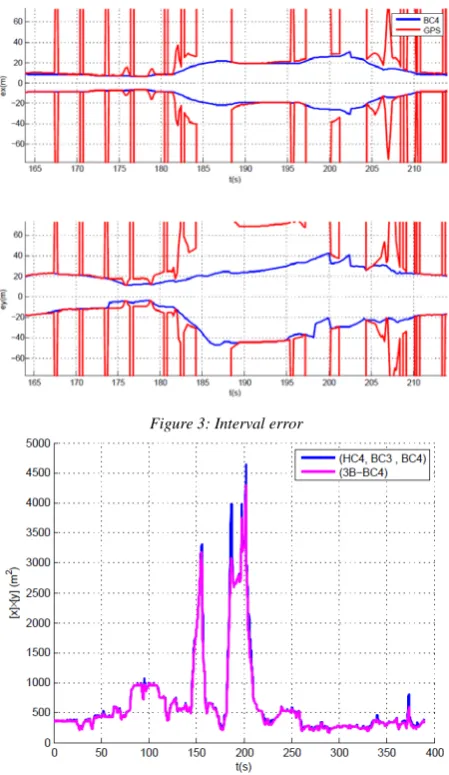
state. Consequently, a localization algorithm exhibits good results if its corridor is thin and if it always in-cludes the zero value (it means that the algorithm im-precision embraces the reference).
The GPS sensor provides consistent measurements (measurements which embrace the reference) with im-portant variations (see Fig. 3). BC4 smoothes in the GPS measurements and acts like a classical Bayesian filter (for instance, an Extended Kalman Filter). HC4, BC3 and BC4 have similar localization results (see Fig. 4). 3B-BC4 provides slightly better localization results than Figure 1: Satory's track
Figure 2: Average localization area and computing time
Figure 3: Interval error
[image:5.595.79.264.510.539.2]the other algorithms. All the compared algorithms pro-vide consistent results contrarily to Bayesian filters that can lose their consistency [30].
6.
Conclusion
Constraint propagation algorithms are often used to solve once an unique system. We have used them on evolving CSPs having a time window in order to solve a localiza-tion problem. We aim at localizing a vehicle equipped with odometers, gyro and GPS. At every time step, the imprecise displacement of the vehicle is measured and the position of the vehicle is corrected with a GPS mea-surement. When a GPS measurement is available, we generate a new small CSP (3 equations) which is added to the current CSP where the three oldest lines are de-leted. We have compared 4 constraint propagation algo-rithms (HC4, BC3, BC4 and 3B-BC4) on the same expe-rimental data. Contrarily to previous works, we shows that it is not necessary to break the constraints into ele-mentary ones [21]. Furthermore, avoiding the use of elementary constraints do not increase the computing time (with ref. to [21]). The 4 tested algorithms provided similar results, although 3B-BC4 provides slightly better contractions than other ones. HC4 and BC4 have similar computing time. BC3 is twice slower than HC4 and BC4. 3B-BC4 is too slow and is not suited for real time issue. Consequently, we recommend the use of HC4 or BC4 for vehicle localization. Further work will deal with an au-tomatic adjustment of the CSP window in order to obtain the best result according to the CPU and the data flow.
REFERENCES
[1] M. Clowes, “On seeing things,” Artificial intelligence, vol. 2,no. 1, pp. 79–116, 1971.
[2] D. Waltz, “Understanding line drawings of scenes with sha-dows,” Psychology of Computer Vision, McGraw-Hill,New York, 1975.
[3] A. Mackworth, “Consistency in networks of relations,” Artificial intelligence, vol. 8, no. 1, pp. 99–118, 1977.
[4] H. Gallaire, “Logic programming: Further developments,” in IEEE Symposium on Logic Programming, pp. 88–99, 1985. [5] J. Jaffar and J. Lassez, “Constraint logic programming,” in ACM
SIGACT-SIGPLAN symposium on Principles of programming languages, pp. 111–119, 1987.
[6] P. Van Hentenryck, Y. Deville, and C. Teng, “A generic arc-consistency algorithm and its specializations,” Artificial In-telligence, vol. 57, no. 2, pp. 291–321, 1992.
[7] C. Bessiere, “Arc-consistency and arc-consistency again,” Ar-tificial intelligence, vol. 65, no. 1, pp. 179–190, 1994.
[8] Z. Yuanlin and R. Yap, “Arc consistency on n-ary monotonic and linear constraints,” International Conference on Principles and Practice of Constraint Programming, pp. 470–483, 2000. [9] R. Dechter and J. Pearl, “Tree clustering for constraint
net-works,” Artificial Intelligence, vol. 38, no. 3, pp. 353–366, 1989. [10] F. Rossi, C. Petrie, and V. Dhar, “On the equivalence of
con-straint satisfaction problems,” in European Conference on Artifi-cial Intelligence, pp. 550–556, 1990.
[11] R. Mohr, G. Masini, et al., “Good old discrete relaxation,” in European Conference on Artificial Intelligence, pp. 651–656, 1988.
[12] J. Cleary, “Logical arithmetic,” Future computing systems, vol. 2, no. 2, pp. 125–149, 1987.
[13] E. Davis, “Constraint propagation with interval labels,” Artificial intelligence, vol. 32, no. 3, pp. 281–331, 1987.
[14] E. Hyvonen, “Constraint reasoning based on interval arithmetic,” in International Joint Conference on Artificial Intelligence, pp. 1193–1198, 1989.
[15] F. Benhamou and W. Older, “Applying interval arithmetic to real, integer, and boolean constraints,” The Journal of Logic Pro-gramming, vol. 32, no. 1, pp. 1–24, 1997.
[16] F. Benhamou, F. Goualard, L. Granvilliers, and J. Puget, “Re-vising hull and box consistency,” in Int. Conf. on Logic Pro-gramming, Citeseer, 1999.
[17] F. Benhamon, D. McAllester, and P. Van Hentenryck, “Clp (intervals) revisited,” tech. rep., Citeseer, 1994.
[18] L. Granvilliers, “Towards cooperative interval narrowing,” Fron-tiers of Combining Systems, pp. 18–31, 2000.
[19] O. Lhomme, “Consistency techniques for numeric csps,” in International Joint Conference on Artificial Intelligence, pp. 232–232,1993.
[20] A. Gning and P. Bonnifait, “Guaranteed dynamic localization using constraints propagation techniques on real intervals,” in IEEE International Conference on Robotics and Automation, pp. 1499–1504, 2004.
[21] B. Vincke, A. Lambert, D. Gruyer, A. Elouardi, and E. Seig-nez,“Static and dynamic fusion for outdoor vehicle localization,” in International Conference on Control Automation Robotics & Vision, pp. 437–442, 2010.
[22] B. Vincke and A. Lambert, “Enhanced constraints propagation for guaranteed localization predictive step,” in IEEE/RSJ IROS, Workshop on Planning, Perception and Navigation for Intelligent Vehicles, pp. 30–36, 2009.
[23] L. Jaulin, “Localization of an underwater robot using interval constraint propagation,” International Conference on Principles and Practice of Constraint Programming, pp. 244–255, 2006. [24] D. L. Waltz, “Generating semantic descriptions from drawings
of scenes with shadows,” PhD thesis, AI Lab, MIT, 1972. [25] D. Gruyer, A. Lambert, M. Perrollaz, and D. Gingras,
“Experi-mental comparison of bayesian vehicle positioning methods based on multi-sensor data fusion,” International Journal of Ve-hicle Autonomous Systems, vol. 10, no. 3-4, 2012.
[26] G. Chabert and L. Jaulin, “Hull consistency under monotonici-ty,” International Conference on Principles and Practice of Con-straint Programming, pp. 188–195, 2009.
[27] R. Moore, Interval analysis. Prentice-Hall Englewood Cliffs, NJ, 1966.
[28] V. Kreinovich, A. Lakeyev, J. Rohn, and P. Kahl, Computational complexity and feasibility of data processing and interval com-putations. Kluwer Academic Publishers Netherlands, 1998. [29] L. Granvilliers and F. Benhamou, “Algorithm 852: Realpaver: an
interval solver using constraint satisfaction techniques,” ACM Transactions on Mathematical Software, vol. 32, no. 1, pp. 138–156, 2006.