Project Management with
SAP
®1 Introduction ... 13
2 Structures and Master Data ... 17
3 Planning Functions ... 121
4 Budget ... 243
5 Project Execution Processes ... 271
6 Period-End Closing ... 345
7 Reporting ... 419
8 Integration Scenarios with Other Project Management Tools ... 471
A BAPIs in SAP Project System ... 491
B Enterprise Services of SAP Project System ... 493
C Selected Project System Database Tables ... 497
D Transactions and Menu Paths ... 499
1 Introduction ... 13
2 Structures and Master Data ... 17
2.1 Basic Principles ... 18
2.1.1 Overview of Project Structures ... 18
2.1.2 Access Control Lists ... 22
2.2 Work Breakdown Structure ... 23
2.2.1 Structure and Master Data ... 25
2.2.2 Structure Customizing of the Work Breakdown Structure ... 35
2.2.3 Standard Work Breakdown Structures ... 44
2.3 Networks ... 45
2.3.1 Structure and Master Data ... 45
2.3.2 Structure Customizing of the Network ... 58
2.3.3 Standard Networks ... 66
2.4 Milestones ... 67
2.4.1 Milestones Assigned to WBS Elements ... 68
2.4.2 Milestones Assigned to Activities ... 70
2.5 Documents ... 72
2.5.1 PS Texts ... 73
2.5.2 Integration with Document Management ... 74
2.6 Statuses ... 75
2.7 Editing Functions ... 79
2.7.1 Project Builder ... 80
2.7.2 Project Planning Board ... 85
2.7.3 Special Maintenance Functions ... 90
2.7.4 Project Editor ... 91
2.8 Tools for Optimized Master Data Maintenance ... 94
2.8.1 Field Selection ... 95
2.8.2 Flexible Detail Screens and Table Controls ... 96
2.8.3 Mass Change ... 97
2.8.4 Substitution ... 100
2.8.5 Validation ... 101
2.8.7 Assembly Processing ... 106
2.9 Versions ... 112
2.9.1 Project Versions ... 112
2.9.2 Simulation Versions ... 115
2.10 Archiving Project Structures ... 117
2.11 Summary ... 120
3 Planning Functions ... 121
3.1 Time Scheduling ... 122
3.1.1 Time Scheduling with WBS Elements ... 124
3.1.2 Scheduling with Networks ... 127
3.2 Resource Planning ... 144
3.2.1 Capacity Planning with Work Centers ... 145
3.2.2 Workforce Planning ... 153
3.2.3 Capacity Leveling ... 160
3.2.4 External Processing ... 163
3.2.5 Service ... 167
3.3 Material Planning ... 170
3.3.1 Assigning Material Components ... 170
3.3.2 Project Stock ... 190
3.3.3 Availability Check ... 194
3.4 Planning Costs and Statistical Key Figures ... 198
3.4.1 Hierarchical Cost Planning ... 202
3.4.2 Unit Costing ... 205
3.4.3 Detailed Planning ... 209
3.4.4 Easy Cost Planning ... 213
3.4.5 Network Costing ... 219
3.4.6 Planned Costs of Assigned Orders ... 227
3.4.7 Planning Statistical Key Figures ... 229
3.5 Revenue Planning ... 231
3.5.1 Hierarchical Planning ... 232
3.5.2 Detailed Planning ... 232
3.5.3 Billing Plan ... 233
3.5.4 Sales Pricing ... 236
4 Budget ... 243
4.1 Budgeting Functions in SAP Project System ... 244
4.1.1 Original Budget ... 245
4.1.2 Budget Updates ... 249
4.1.3 Budget Release ... 252
4.1.4 Budget Carryforward ... 253
4.1.5 Availability Control ... 255
4.2 Integration with Investment Management ... 262
4.3 Summary ... 269
5 Project Execution Processes ... 271
5.1 Actual Dates ... 272
5.1.1 Actual Dates of WBS Elements ... 272
5.1.2 Actual Dates of Activities ... 273
5.1.3 Actual Dates of Milestones ... 275
5.2 Account Assignment of Documents ... 276
5.2.1 Commitments Management ... 277
5.2.2 Manual Account Assignment ... 280
5.2.3 Execution Services ... 281
5.3 Confirmations ... 284
5.3.1 Individual Confirmations ... 291
5.3.2 Collective and Summary Confirmations ... 292
5.3.3 Cross-Application Time Sheet (CATS) ... 293
5.3.4 Additional Confirmation Options ... 297
5.4 External Procurement of Services ... 298
5.4.1 External Processing ... 298
5.4.2 Service ... 301
5.5 Material Procurement and Delivery ... 303
5.5.1 Material Procurement Processes ... 303
5.5.2 Delivery from Project ... 311
5.5.3 ProMan ... 313
5.6 Billing ... 317
5.6.1 Milestone Billing ... 317
5.6.2 Resource-Related Billing ... 320
5.7 Project Progress ... 324
5.7.2 Progress Analysis ... 326
5.7.3 Progress Tracking ... 336
5.8 Claim Management ... 340
5.9 Summary ... 344
6 Period-End Closing ... 345
6.1 Processing Types ... 346
6.2 Revaluation at Actual Prices ... 349
6.2.1 Prerequisites for Revaluation at Actual Prices ... 350
6.2.2 Executing the Revaluation at Actual Prices ... 351
6.2.3 Dependencies of the Revaluation at Actual Prices ... 351
6.3 Overhead Rates ... 352
6.3.1 Prerequisites for the Allocation of Overhead Rates ... 352
6.3.2 Executing the Application of Overhead ... 355
6.4 Template Allocations ... 357
6.4.1 Prerequisites for Template Allocation ... 357
6.4.2 Executing Template Allocation ... 359
6.5 Interest Calculation ... 360
6.5.1 Prerequisites for Interest Calculation for Projects ... 361
6.5.2 Executing the Interest Calculation for Projects ... 367
6.6 Results Analysis ... 369
6.6.1 Prerequisites for the Results Analysis ... 376
6.6.2 Executing the Results Analysis ... 384
6.7 Project-Related Incoming Orders ... 386
6.7.1 Prerequisites for Project-Related Incoming Order Determination ... 389
6.7.2 Executing the Project-Related Incoming Order Determination ... 392
6.8 Cost Forecast ... 393
6.8.1 Prerequisites for and Restrictions of the Cost Forecast ... 396
6.8.2 Executing and Evaluating the Cost Forecast ... 397
6.8.3 Forecast Workbench ... 398
6.9.2 Executing Project Settlements ... 411
6.9.3 Settlement of Investment Projects ... 414
6.9.4 Project Settlement Dependencies ... 417
6.10 Summary ... 418
7 Reporting ... 419
7.1 Project Information System: Structures ... 419
7.1.1 Structure/Project Structure Overview ... 424
7.1.2 Individual Overviews ... 429
7.2 Project Information System: Financials ... 432
7.2.1 Hierarchy Reports ... 432
7.2.2 Cost Element Reports ... 441
7.2.3 Line Item Reports ... 447
7.2.4 PS Cash Management ... 450
7.3 Logistical Reports ... 456
7.3.1 Purchase Requisitions and Purchase Orders for the Project ... 456
7.3.2 Material Reports ... 458
7.3.3 Capacity Reports ... 459
7.4 Project Summarization ... 466
7.5 Summary ... 470
8 Integration Scenarios with Other Project Management Tools ... 471
8.1 Open PS for Microsoft Project ... 473
8.2 cProjects ... 477
8.3 SAP Resource and Portfolio Management ... 482
8.4 Summary ... 487
Appendices ... 489
A BAPIs in SAP Project System ... 491
B Enterprise Services of SAP Project System ... 493
D Transactions and Menu Paths ... 499
D.1 Structures and Master Data ... 499
D.1.1 Transactions in the SAP Menu ... 499
D.1.2 Customizing Activities ... 500
D.2 Planning Functions ... 503
D.2.1 Transactions in the SAP Menu ... 503
D.2.2 Customizing Activities ... 505
D.3 Budget ... 507
D.3.1 Transactions in the SAP Menu ... 507
D.3.2 Customizing Activities ... 508
D.4 Project Execution Processes ... 509
D.4.1 Transactions in the SAP Menu ... 509
D.4.2 Customizing Activities ... 511
D.5 Period-End Closing ... 511
D.5.1 Transactions in the SAP Menu ... 511
D.5.2 Customizing Activities ... 513
D.6 Reporting ... 514
D.6.1 Transactions in the SAP Menu ... 514
D.6.2 Customizing Activities ... 516
E The Author ... 519
enues for the individual project parts. Therefore, project planning constitutes an important aspect of project management.
Planning Functions
3
Once you have properly mapped a project using the work breakdown structure (WBS) and the network structure, you can use various SAP Project System functions to plan the dates of the individual work pack-ages, estimate the expected costs and revenues, and provide internal and external resources and materials on schedule before the project starts.
Depending on your requirements, there are planning functions with different levels of detail. For example, within a quotation or approval phase, you can create a preliminary plan of dates and costs with very little effort and add specifications later, if necessary, using other planning functions or additional structures.
In the implementation phase, the planned data is compared with actual data that is posted to the project structures by different business trans-actions (see Chapter 5, Project Execution Processes). In the processing transactions, particularly in the reporting of SAP Project System, you can therefore make a plan/actual comparison later and then monitor the project earned value.
Time Scheduling
3.1
The planning of the dates of a project or parts of a project is integral to your project planning. The planning of capacity requirements (see Section 3.2.1, Capacity Planning with Work Centers), for example, requires prior scheduling. The cost planning via Easy Cost Planning (see Section 3.4.4, Easy Cost Planning) or network costing (see Section 3.4.5, Network Cost-ing) is automatically aligned with the planned project dates as well.
Depending on whether you use work breakdown structures or net-works for structuring your projects, different functions are available for planning dates. These are discussed separately in Sections 3.1.1, Date Planning with WBS Elements, and 3.1.2, Scheduling with Networks, respectively. If you use both a work breakdown structure and networks, scheduling data can be exchanged between the WBS elements and the activities, which is discussed in Section 3.1.2 as well.
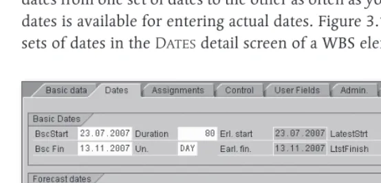
Regardless of the structures you use for mapping your projects (WBS or network), there are two separate sets of dates available for time schedul-ing in SAP Project System: basic dates and forecast dates.1 You can sched-ule dates in both sets of dates separately; however, you can also copy dates from one set of dates to the other as often as you like. A third set of dates is available for entering actual dates. Figure 3.1 shows the various sets of dates in the Dates detail screen of a WBS element.
[image:10.539.98.375.381.514.2]Dates Detail Screen of a WBS Element
Figure 3.1
1 Don’t confuse the forecast set of dates with the forecast dates you can enter in the
The calculation of capacity requirements, the requirement date of material components or, for example, the Easy Cost Planning and the planned costs calculation using network costing are exclusively based on the dates of the basic set of dates.
Typically, the forecast set of dates is used for baselining, that is, fixing planned dates at a specific planning stage. To do this, you copy the dates of the basic set of dates into the forecast set of dates. Changes to dates at a later stage are made to the basic set of dates, while the dates in the forecast set of dates unchanged. Therefore, you can always read the cur-rent status of time scheduling in the basic set of dates while the forecast set of dates reflects your original time schedule. If you want to maintain several stages of time scheduling, you can use project versions (see Chap-ter 2, Section 2.9.1, Project Versions).
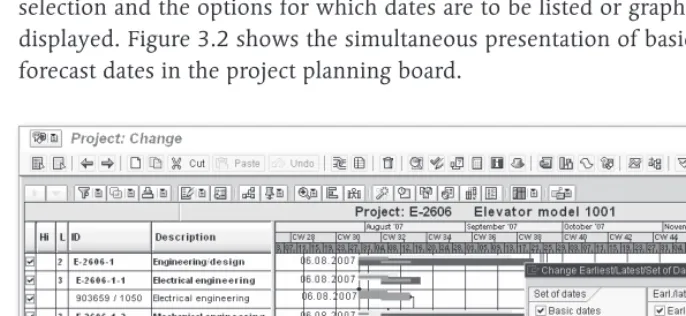
The presentation of forecast dates depends on the respective transac-tion. The tabular presentation of structure planning contains, for exam-ple, separate tabs for the respective sets of dates (see Chapter 2, Section 2.7.3, Special Maintenance Functions). In Project Builder, the WBS ele-ments detail screen shows all sets of dates, while either the basic set of dates or the forecast set of dates is displayed for networks, depending on the settings. In the project planning board, you determine the field selection and the options for which dates are to be listed or graphically displayed. Figure 3.2 shows the simultaneous presentation of basic and forecast dates in the project planning board.
[image:11.539.57.400.401.559.2]Time Scheduling with WBS Elements 3.1.1
When creating a project, you can enter a planned start and end date for the project in the project definition. When you later schedule dates on the WBS elements level, the system notifies you if the WBS element dates are outside of the date range specified in the project definition. If you want, however, start and end dates of the project definition can be adapted to the dates of the WBS elements.
Dates for WBS elements can be scheduled in Project Builder in the WBS elements detail screen, in the project planning board, or via the spe-cial maintenance functions, either in a tabular format or, in the project planning board, in a graphical format. Optionally, you can specify both planned start and end dates, or one of the two along with a planned duration for the WBS element. The system then calculates the other date automatically.
In this time scheduling, the system considers the factory calendar of the WBS element, which distinguishes workdays and non-workdays (holi-days, weekends, company holi(holi-days, etc.). The entered duration in (holi-days, for example, is interpreted as the number of workdays; start or end dates on nonworkdays cause system warnings.2
The standard version already contains numerous predefined factory cal-endars. You can also define your own factory calendars in Customizing using Transaction SCAL. Select the factory calendars separately for every WBS element, or enter them as default values in the project definition or in the project profile.
In addition to the manual maintenance of planned dates for WBS ele-ments, there are various functions that — depending on the transaction — support you in your time scheduling tasks. Using the project planning board as an example, we will explain in detail various time scheduling functions for WBS elements without assigned activities.
Using the Shift dates function, you can shift the planned dates of indi-vidual WBS elements, or of entire subtrees, or of your entire project.
2 In the project planning board, the maintenance and presentation of non-working times are controlled by the non-working time tag in the options or the planning
Factory calendar
For example, if you select a WBS element and choose the Shift Subtree
function, a dialog box opens in which you can either enter a new start or a new end date, depending on the WBS scheduling parameters (see Section 3.1.2, Scheduling with Networks). The system then shifts both the WBS element and all subordinate WBS elements accordingly.
Because WBS elements do not have relationships, the shifting of WBS ele-ments does not automatically cause the planned dates of WBS elements on the same level to be shifted.
Using the Copy top-down function, you can copy the start and end dates of a WBS element to all hierarchically subordinate WBS elements.3 Exist-ing planned dates are thereby overwritten.
Instead of inheriting dates in a top-down fashion, you can, in turn, aggregate dates within the work breakdown structure hierarchy using the Extrapolate dates function. Using this function you have to distin-guish between bottom-up and strict bottom-up extrapolation.
If you run the Extrapolate Dates function for your project and if the
Open planning or Bottom-upplanning method has been set, the date ranges of the project definition and of all WBS elements are adapted so that they span the dates of the respective subordinate WBS elements. The date ranges of higher-level objects are therefore extended, if neces-sary, but not reduced. This means the date range of an object can there-fore be larger than that of the subordinate objects.
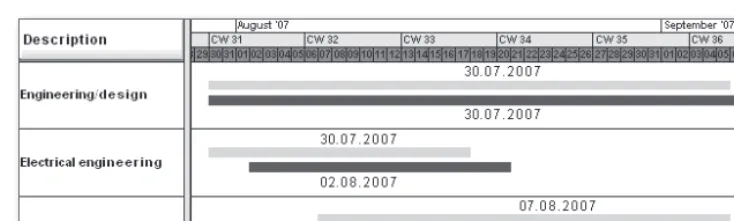
Figure 3.3 shows an example of the bottom-up projecting of WBS ele-ment dates. The dates of the WBS eleele-ments Electrical engineering and
Mechanical engineering have been time-shifted and the dates have been projected to the higher-level Engineering/design WBS element. The upper time bars (forecast dates) correspond to the dates before; the lower time bars (basic dates) correspond to the dates after the shifting and projecting process.
3 If activities are assigned to the WBS element, the WBS dates can be inherited to
Inheriting dates
Projecting dates
Bottom-up Projection
Figure 3.3
If you execute the Extrapolate dates function for a project for which the Strict bottom-up planning method has been set, the date ranges of the project definition and of all WBS elements are accurately adapted to the scheduling frameworks of the subordinate WBS elements (see Figure 3.4). The date ranges of higher-level objects are thus both extended and reduced, if necessary.
Prioritized Bottom-up Projection
Figure 3.4
Another function you can implement when time scheduling with WBS elements is the Check dates within project structure function. The system then highlights WBS elements in color where planned dates of the subordinate WBS elements are outside of the scheduling framework of the WBS element itself. You can therefore avoid hierarchically incon-sistent time scheduling for projects.
Using so-called planning methods, several of the functions just mentioned can be automatically executed during the saving process, regardless of the processing transaction. The following planning methods are available:
Strict bottom-up projecting
Checking dates within project structure
[image:14.539.46.414.290.400.2]Top-down
E E
When saving, the system automatically checks the dates within the project structure. If the time scheduling is not consistent, the project cannot be saved. However, no dates are automatically changed.
Bottom-up
E E
When saving, the system automatically changes the dates of WBS ele-ments and project definition via bottom-up extrapolation.
Strict Bottom-up
E E
When saving, the system automatically changes the dates of WBS ele-ments and project definition using a strict bottom-up extrapolation.
Open Planning
E E
The system does not automatically check or change the dates. How-ever, you can manually trigger the Check dates within project structure or Extrapolate dates functions.
You specify the planning method to be used separately for the basic and the forecast set of dates in the project definition. In the project profile, you can store default values for the planning methods of both sets of dates.
If you work with WBS without assigned networks, the scheduled dates of WBS elements, i.e., their earliest and latest start and end dates (see Figure 3.1), are only relevant if you use milestones, the dates of which are derived from the WBS element dates. Because the dates of mile-stones are exclusively derived from the scheduled dates, you must run the WBS Scheduling function at least once in this case. For WBS with-out assigned networks, the WBS scheduling only causes the planned dates to be accepted as scheduled dates.
Scheduling with Networks 3.1.2
In network scheduling, only one network is scheduled. All activities of the network are selected and their dates are calculated. If you use over-all network scheduling, several networks are scheduled at the same time, provided they are linked via relationships or subnetworks. All activities of these networks are then scheduled. In WBS scheduling, you select one or more WBS elements, or the entire project, and trigger the scheduling process. The system now selects only those activities for scheduling that are assigned to the selected WBS elements and calculates their dates.
Before we elaborate on more differences between the various schedul-ing methods, we will first describe the schedulschedul-ing concept, which is the same for all three methods.
In SAP Project System, the scheduling always takes place both in a forward and backward direction.
In forward scheduling, the system first determines those activities that — due to their relationships — don’t have any predecessors among the selected activities. Beginning with a start date, the system calculates the earliest possible start date for these activities. Depending on the schedul-ing settschedul-ings, the start date of forward schedulschedul-ing can originate from the header of the network or from the assigned WBS elements (WBS deter-mines the dates), or be the current date.
After the earliest start date of these activities has been determined, the system calculates the earliest possible end date of these activities using the scheduling-relevant duration. Then, the system selects the direct suc-cessors of these activities and calculates their earliest start and end dates. Each type of relationship (see Section 2.3.1, Structure and Master Data) determines whether the earliest start date must be after the end date of its predecessors (finish-start) or after their start date (start-start), etc.
The scheduling now goes through all selected activities in a forward direction and calculates their earliest possible start and end dates. For-ward scheduling results in the earliest dates of activities.
In backward scheduling, the system first determines those activities that — due to their relationships — don’t have any more successors among the selected activities. Starting from an end date — depending
Forward scheduling
Earliest dates
on the settings of the network header or the assigned WBS elements — the system now calculates the latest possible end date of these activities. Based on the scheduling-relevant duration of the activities, the latest start dates of these activities are then calculated.
The system then goes through the network in a backward direction, fol-lowing the relationships, and thus successively calculates the latest pos-sible start and end dates for all selected activities, considering their types of relationship and their durations. Backward scheduling determines the latest dates of activities.
The earliest start date and the latest end date of the network activities are forwarded to the network header as the scheduled dates. In WBS sched-uling, the activity dates are also indicated in an aggregated fashion as scheduled dates at the level of the assigned WBS elements.
This logic of forward and backward scheduling requires a number of additional notes regarding the various influencing factors that are rel-evant to scheduling.
Without relationships, the result of scheduling in SAP Project System would not be a chronological sequence of the activities. The type of relationship determines how two activities will interact chronologically. If you specified a time interval for a relationship, this will be taken into account during scheduling. This time interval, however, is only inter-preted as a minimum time interval, that is, the scheduled time interval between predecessor and successor can be longer than the time interval defined in the relationship.
If the activities selected for scheduling have relationships to activities that are not scheduled at the same time, these relationships are still taken into account. If relationships cannot be met, the system issues warnings that you can analyze in a scheduling log.
The calculation of the scheduling-relevant duration and the consider-ation of nonworking times depend on the respective activity type; how-ever, for all activity types, the control key of the activities must permit scheduling so that a duration unequal to zero is used during the date calculation.
Latest dates
Relationships in scheduling
For internally processed activities, the scheduling-relevant duration — as long as no actual dates have been entered (see Chapter 5, Section 5.1.2, Actual Dates of Activities) — is derived from the value of the Normal duration field or, if a work center has been stored in the activity, from an appropriate formula in the scheduling details of the work center. Typi-cally, however, you will store the standard formula SAP004 in the work center, which references the value of the Normal duration field in the activity.
The Unit of the Normal duration field is relevant as well. For example, if you enter a duration of 24 hours, these hours are interpreted as work-ing hours. If the schedulwork-ing-relevant capacity of the work center has an operating time of eight hours per day, this results in a scheduling-rele-vant duration of three (working) days. If you entered a duration of one day, the system would only use one (working) day as the scheduling-relevant duration.
The scheduling of internally processed activities also considers nonwork-ing times. If you maintained a work center in the activity, the system only uses the working times of the scheduling-relevant capacity of the work center for scheduling. Start and end dates are only scheduled for working days. The differentiation between working and nonworking days originates from a factory calendar that is determined according to the following priority:
Factory calendar in the activity 1.
Factory calendar in the work center 2.
Factory calendar of the plant in the activity 3.
For externally processed activities and service activities, the system, by default, uses the planned delivery time as the scheduling-relevant dura-tion without differentiating between working and nonworking days. But, if you want to use a deviating duration for scheduling, you can define a control key with the Scheduling external operation indicator and manually enter the scheduling-relevant duration in the Normal dura-tion field of the Internal tab.
For general costs activities, you can manually specify the scheduling-rel-evant duration via the Normal duration field. Using factory calendars in the costs activities, you can restrict scheduling to working days.
If necessary, the system can automatically reduce the duration of activi-ties if the scheduled dates are outside of the basic or forecast dates of the network header. The system can therefore automatically adapt the duration of activities to enable the network to be carried out in a given timeframe. This automatic adaptation of activity durations is called reduc-tion. By specifying a minimum duration in an activity, you can ensure that a time interval that is required for processing an activity is not fur-ther reduced.
The reduction of the activity durations is performed in several successive stages. In the first stage, for example, the durations could be reduced by 10%. If this reduction is not sufficient, the originally planned durations could be reduced by 15% in a second stage, and so forth. A maximum of six stages could be implemented. After scheduling, you will find the actual number of required reduction levels in the network header.
For a system to automatically reduce the duration of an activity, you must store a reduction strategy in the activity. In the definition of a reduc-tion strategy, for each reducreduc-tion level, you specify the percentage by which the planned duration of an activity is to be reduced. Figure 3.5 shows an example of the definition of a reduction strategy in the Cus-tomizing of SAP Project System.
Finally, you need to specify in the scheduling parameters that a reduc-tion is to be carried out. To do this, you specify the maximum number of levels to run through. In addition, you can specify in the scheduling parameters whether all activities that have a reduction strategy are to be reduced or only those that are time critical.
Scheduling calculates the planned earliest and latest dates of activities, and the scheduled dates of network headers and WBS elements. The cor-responding fields cannot be changed manually.
Reduction
Reduction levels
Reduction strategy
Example of a Reduction Strategy
Figure 3.5
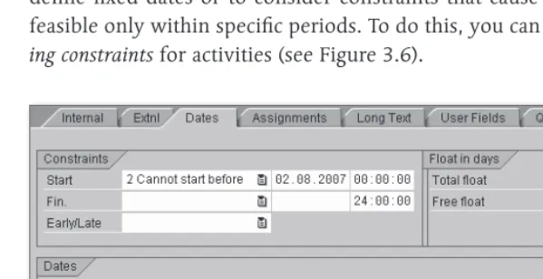
However, you may want to assist in scheduling activities to, for example, define fixed dates or to consider constraints that cause activities to be feasible only within specific periods. To do this, you can specify schedul-ing constraints for activities (see Figure 3.6).
Example of a Scheduling Constraint for an Activity
[image:20.539.97.397.363.517.2]Using scheduling constraints, you can either fix the earliest or latest start or end dates of activities (Must start/finish on) or restrict them via threshold values (Cannot start/finish before/not later). You can manually enter scheduling constraints or graphically determine them in the project planning board, depending on the options or the planning board profile (see Chapter 2, Section 2.7.2, Project Planning Board). In scheduling, the various influencing factors are considered according to the following prioritization:
Actual dates (see Chapter 5, Section 5.1.2, Actual Dates of Activities) 1.
Scheduling constraints 2.
Relationships 3.
Start and end dates of the network header or the assigned WBS ele-4.
ments if the work breakdown structure determines dates
From the scheduled dates of the activities, the system also determines floats for each activity, which can be displayed in the detail screen of the activities and the network graphic, or graphically illustrated in the proj-ect planning board, respproj-ectively. Regarding floats, there is a distinction between a total float and a free float.
The total float of an activity results from the difference between its lat-est and earlilat-est dates, and therefore specifies the time interval by which you can shift an activity from its earliest date without exceeding the end date defined in the network header or — if it determines dates — of the assigned WBS element. Activities with a total float smaller than or equal to zero are regarded as time-critical and are highlighted in color in the network graphic and the diagram section of the project planning board.4
The free float of an activity is the interval by which you can shift the activity from its earliest date without affecting the earliest date of the succeeding activities. For two activities that are linked to each other by a finish-start relationship (without a time interval), the free float of the
pre-4 In the project planning board, you can use the options or even the planning board profile to control the total float starting from which activities are to be highlighted
Floats
Total float
decessor results, for example, from the difference between the earliest start date of the successor and the earliest end date of the activity itself.
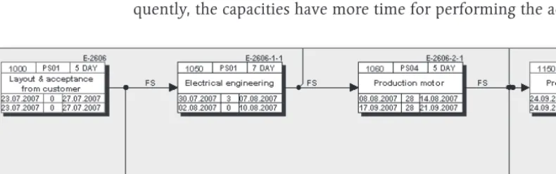
Free floats typically result from scheduling constraints of succeeding activities, or they occur when there are parallel paths within the network where one path consumes more time than the other (see Figure 3.7). Because you can use the free float to perform activities without affecting subsequent activities with regard to scheduling, you can set the Flex-ible indicator for an activity to cause the earliest dates of this activity to be calculated based on the normal duration plus the free float. Conse-quently, the capacities have more time for performing the activity.
[image:22.539.19.414.208.332.2]Time-critical Activities and Floats in the Network Graphic
Figure 3.7
You can supplement activities or add more details (see Section 2.3.1, Structure and Master Data) via activity elements. Because activity ele-ments don’t have a duration or relationships, they don’t affect the sched-uling result. Just like activities, however, activity elements have earliest and latest start and end dates. These dates are derived from the sched-uled dates of the activity to which the activity elements are assigned and from the time intervals you may have entered in the activity elements.
The planned dates of the activity elements always fall within the activity dates. Scheduling constraints can be defined at an activity level, but not for activity elements.
“Flexible” indicator
For milestones you have assigned to activities, you can either manually enter fixed dates or establish a time reference to the activity. If you use a time reference, you can use appropriate indicators to specify whether the milestone date is to be taken from the earliest or latest date, and the start or the end date of the activity. Furthermore, you can specify a time interval either in absolute terms (e.g., in a number of days), or in terms of percentage based on the duration of the activity. When using a time reference, every date shift of the activity directly affects the milestone date.
Even if you assign material components to an activity (see Section 3.3.1, Assigning Material Components), you can select between a fixed require-ment date for the material and a requirerequire-ment date that is derived from the start or the end of the activity. The scheduling parameters control whether the date reference should refer to the earliest or the latest date of the activity. If necessary, you can also specify an absolute time interval that is considered when deriving the requirement date from the activity date.
Network Scheduling
In network scheduling, all activities of an individual network are sched-uled. Whenever you call the scheduling from the specific maintenance function CN22 or from the Project Builder, provided you have selected a network header or a network activity in the structure tree, you trigger a network scheduling.
In network scheduling, the scheduling settings are determined from the network scheduling parameters, but can also be temporarily modi-fied. Figure 3.8 shows an example of defining network scheduling parameters.
Before you can create a network, you must have defined Network Schedul-ing Parameters for the combination of the plant and the network type of the network header in the Customizing of SAP Project System (Transaction OPU6).
Dates of activity milestones
Requirement date of material components
Network Scheduling Parameters
Figure 3.8
In the scheduling parameters, you first store the Scheduling Type. This value is displayed at the network header level and can be changed there, if necessary. The following scheduling types are available in SAP Project System:
Forward
E E
The system first performs a forward and then a backward scheduling. You use this scheduling type if you know the start of the execution, but not its end date.
Backward
E E
The system first performs a backward and then a forward scheduling. You use this scheduling type if you know the end of the execution (e.g., an agreed delivery date), but not its start date.
Current Date
E E
Instead of start dates that lie in the past, the system uses the current date for forward scheduling. You can therefore see if the planned period for the execution is still sufficient and which floats may still be available. This also includes both forward and backward scheduling.
Only Capacity Requirements
E
E
The activities use the start and end dates from the network header (or the assigned WBS elements, if they determine dates) as the earliest and latest start and end dates. Relationships or the duration of indi-vidual activities are not taken into account in this scheduling type. You can implement this scheduling type if you don’t want to specify any details (yet) about the process and duration of individual activi-ties, but want to calculate the capacity requirements for the total run-time (see Section 3.2.1, Capacity Planning with Work Centers).
In SAP Project System, start and end dates for scheduling can be specified in the network header or the WBS elements to the day only. Scheduling types with a reference to the time of the day can not be implemented in SAP Proj-ect System.
Using the Adjust basic dates indicator in the scheduling parameters, you control if the system accepts the scheduled dates at the network header level as basic or forecast dates. For example, if there is a fixed timeframe for the execution, enter the start and end dates manually in the network header and set the Do not adjust basic dates indicator. Your dates will remain fixed during the scheduling process, and by com-paring the scheduled dates, you can determine whether the timeframe is sufficient for the execution.5
However, if you only know the start date, for example, and want the sys-tem to calculate the end date and to adjust it if changes need to be made at a later stage, select the Forwards scheduling type, set the Adjust basic dates indicator and manually enter a start date in the network header. Based on your start date, the system first calculates the sched-uled end of the network, inserts it as the end date, and then performs the backward scheduling based on this date.
5 If the scheduled dates are outside of the predefined dates, the scheduling log issues
The number of days you enter in the Startin the Past field in the sched-uling parameters controls the handling of start dates that have already passed. If the system determines a start date during scheduling that is further in the past than you permitted in the Start in the Past field,6 the system issues a warning and automatically uses the current date for forward scheduling (this is called today scheduling).
By setting the Automatic Scheduling indicator in the scheduling param-eters, you cause a scheduling to be performed automatically when the network is saved whenever there has been a scheduling-relevant modi-fication to the network. The indicator is forwarded as a default value to the network header and can be changed there. At the latest, during the implementation phase of a network, it is usually recommended that you remove this indicator from the network header to avoid uncontrolled changes to capacity requirements, purchase requisitions, or reservations of material due to automatic scheduling.
Other indicators in the scheduling parameters control the output of scheduling logs in Transaction CN22, the handling of breaks in the scope of scheduling, the date reference of material components, the consider-ation of actual dates from partial confirmconsider-ations (see Chapter 5, Section 5.3, Confirmations), and how later date changes affect a workforce plan-ning (see Section 3.2.2, Workforce Planplan-ning).
Overall Network Scheduling
In overall network scheduling, all networks or orders that are linked to each other via external relationships or subnetworks are scheduled at the same time. Overall network scheduling is run automatically within the assembly processing (see Section 2.8.7, Assembly Processing) or started from a sales and distribution document. You can trigger overall network scheduling in SAP Project System using Transaction CN24 or CN24N.
During overall network scheduling, the scheduling settings are deter-mined, just like in network scheduling, from the scheduling parameters for the network type.
6 If you enter 999 in the Start in the Past field, the system permits start dates that
Start in the Past
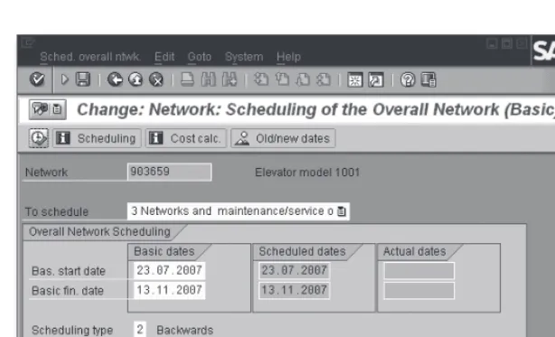
If you use Transaction CN24 for overall network scheduling, first specify the identification of a network and the set of dates for scheduling. Then you can make temporary changes to the scheduling settings, if necessary, or enter new start and end dates for scheduling (see Figure 3.9).
[image:27.539.57.364.120.306.2]Overall Network Scheduling Using Transaction CN24
Figure 3.9
If you work with maintenance or service orders as assigned subnet-works, you can use the To schedule field to determine whether only these orders are to be scheduled, only the networks, or both networks and assigned maintenance or service orders.
After you have performed the scheduling you can use the Old/new dates function to compare the old dates to the newly calculated dates. Afterward, you can save the date changes of the networks or orders, respectively.
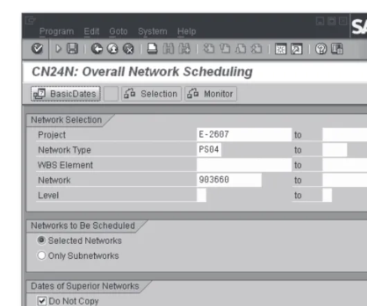
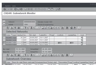
In contrast to Transaction CN24, Overall Network Scheduling with Selection Options (Transaction CN24N), which is available by default from SAP ECC 5.0, enables you to influence the selection of the net-works and subnetnet-works to be scheduled before the scheduling process (see Figure 3.10) and to also use a monitor for observing the dates of subnetworks.
CN24 (Overall network scheduling)
CN24N
Overall Network Scheduling with Selection Options
Figure 3.10
In the Subnetwork Monitor, both data from the selected networks and data from the assigned subnetworks are displayed in a table (see Figure 3.11). You can go to the activity or network header display by clicking on your mouse. In addition, you can enter activity confirmations in the
Subnetwork Monitor or call the Project Information System: Structures (see Chapter 7, Section 7.1, Project Information system: Structures). Traf-fic lights indicate when the dates of the subnetworks are outside of the dates the higher-level activity (Conflict) or don’t exactly match (Update required).
To use the functions of overall network scheduling with selection options in the Customizing of SAP Project System, you need to define levels in addition to the scheduling parameters for the network type, and then manually assign these levels to the network types and number range intervals of the networks and subnetworks. The level definition must reflect the hierarchical arrangement of the networks and subnetworks. The levels serve as selection criteria in Transaction CN24N. A scheduling using Transaction CN24N can span a maximum of two levels.
Subnetwork Monitor
[image:28.539.98.363.50.271.2]Subnetwork Monitor
Figure 3.11
Transaction CN24N is intended primarily for companies that work with a large number of multilevel subnetwork structures and that don’t always want to schedule all networks and subnetworks at the same time when scheduling.
WBS Scheduling
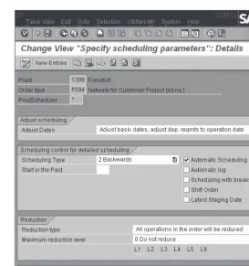
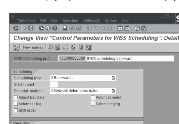
[image:29.539.59.441.48.308.2]In WBS scheduling, the scheduling settings are determined from the
Control Parameters for WBS Scheduling, but can also be changed temporarily. These control parameters are grouped in a profile that you can define in the Customizing of SAP Project System (see Figure 3.12) and enter in the project profile as a default value for the project definition.
Control Parameters for WBS Scheduling
Figure 3.12
The control parameters for WBS scheduling basically contain the same settings as the parameters of network scheduling, that is, the scheduling type, an indicator for automatically scheduling at saving time, or reduc-tion settings. If you set the Adjust basic dates in WBS scheduling, not only are the network header dates adapted to the scheduled dates, but the planned dates of the WBS elements are also derived from the sched-uled dates of the assigned activities. For that reason, the planned dates of activities and WBS elements can be determined at the same time during a WBS scheduling.
In addition, the parameters for WBS scheduling include the Scheduling method field with the following two options:
Parameters for WBS scheduling
[image:30.539.98.401.133.342.2]Network determines dates
E
E
The network header determines the start and the end date of schedul-ing.
WBS determines dates
E E
The planned dates of the WBS element determine the start and end dates for scheduling the assigned activities.
Therefore, the idea of the WBS determines dates scheduling method is to first make a manual time schedule at the WBS element level and to then schedule the assigned activities. The scheduling of the activities is then based on the manually planned start and end dates of the WBS elements.
In the time scheduling process using WBS elements and networks, the scheduling parameters controlling the scheduling of the activities and the data exchange with the WBS elements play an important role, and the planning methods controlling the hierarchical exchange of planned dates between WBS elements on different levels. You can define the WBS scheduling parameters in the Customizing and specify them together with the planning methods for your project. Alternatively, you can also use predefined scheduling scenarios with WBS elements and networks.
If you select a scheduling scenario for scheduling a project, all settings are determined via the scheduling scenario. The following scheduling scenarios exist:
Bottom-up scenario
E
E
Based on the basic start date of the network header (which may be anywhere in the past), a forward scheduling and then a backward scheduling are performed. The scheduled dates are used as planned dates at the network header level and the assigned WBS elements. The planned dates of the WBS elements are finally projected in a bot-tom-up fashion.
Top-down scenario
E E
In this scenario, you first have to make a manual scheduling at the WBS element level. During this process, the system checks the hierar-chical consistency of this time scheduling when scheduling or saving. The scheduling of the assigned activities is based on the planned dates of the WBS elements (which may be anywhere in the past).
In both scheduling scenarios, requirement dates for material are derived from the latest date of activities, and reductions are not performed. The settings of both scheduling scenarios, bottom-up and top-down, are pre-defined and cannot be changed.
If you want to use one of the two scheduling scenarios, you can store the scenario in the project definition or enter it as a default value in the project profile. However, if you want to use different settings, you need to set the Scheduling scenario field to the Free scheduling value and specify the appropriate settings manually.
Summary
Using scheduling, you can have the system automatically calculate the planned dates of activities and assigned objects, and identify time-critical activities. If the activities are assigned to WBS elements, date information can be exchanged between the activities and the WBS elements. If necessary, you can manually schedule dates at the WBS element level. You are supported by various functions like, for example, the projecting of dates or hierarchical consistency checks.
Resource Planning
3.2
Capacity Planning
3.2.1 with Work Centers
When structuring your projects, you use internally processed activi-ties or activity elements for specifying services that will be provided by internal resources, for example, machine or personnel resources. Within scheduling, the system has calculated when these services will be per-formed; however, the scheduling doesn’t verify whether there are suf-ficient internal resources at the planned date. To make statements about the availability of your resources and thus the feasibility of your projects in terms of capacities, you can use the capacity requirements planning in SAP Project System.
The primary function of capacity requirements planning is to determine capacity requirements and to periodically (e.g., on a weekly or daily basis) compare these requirements with the available capacity using the appro-priate reports (see Chapter 7, Section 7.3.3, Capacity Reports). The avail-able capacity is defined using work centers, while the required capacity is derived from the activity data of networks or, for example, production or maintenance orders. If you discover that the capacity requirement is higher than the available capacities during a specific period, you will need to make a capacity leveling to get your planning in line with the capacities.
A prerequisite for capacity requirements planning using networks is the usage of work centers.
Definition of Work Centers and Available Capacity
Work centers are organizational units in the SAP system that define where an activity can be performed and by whom. If you have already defined work centers for production or maintenance, you can use these work centers in networks as well, provided that this is permitted by the appli-cation of the work centers. If you have not yet defined any work centers in the SAP system, or if you want to use separate work centers for proj-ects, you can create new work centers in SAP Project System (Transac-tion CNR1).
When creating a new work center, in addition to the identification and the plant of the work center, you also specify the Work center category
Capacity requirements planning
(see Figure 3.13). Among other things, the work center category defines the fields (Field selection) and tabs (Screen sequence) to be displayed in the master record of the work center. By default, you can use the 0006
(Project management) work center category in SAP Project System. If required, you can define additional work center categories (Customizing Transaction OP40).
Definition of Work Center Categories
Figure 3.13
The Usage field in the basic data of the work center determines the task list types and order categories in which the work center can be used. For a work center to be used in standard networks and particularly in operative networks, it must have a usage that is assigned to the task list type 0 (standard network). If the work center is to be exclusively used for networks, you can, for example, enter the application 003 (networks only) in the master record of the work center. If you want, you can use Customizing Transaction OP45 to define your own usages and assign them to the relevant task list types.
Depending on the work center category, you can make a number of set-tings for the time scheduling (see Section 3.1.2, Scheduling with Net-works) and the calculation (see Section 3.4.5, Network Costing) of
[image:34.539.71.413.147.329.2]ties in the master data. For capacity requirements planning, however, the settings on the Capacities tab are relevant.
On this tab, you first store one or more Capacity Categories, for exam-ple, for persons or machines, and then define the respective available capacity. Capacity categories are defined in Customizing and specify, among other things, whether the available capacity must be defined in time units or in base or volume units, or whether, for example, you can assign persons from Human Resources (HR).
In the simplest case, the definition of an available capacity consists of the specification of a factory calendar for distinguishing working and nonworking days, information about the beginning, the end, and the duration of breaks of a working day, the specification of a capacity uti-lization rate, and the number of available individual capacities. The rate of capacity utilization describes how much of the daily working time can actually be used for production. The available capacity finally results from the productive operating time of a capacity, multiplied with the number of individual capacities (see Figure 3.14).
In addition to the definition of the standard available capacity, there are several more detailed options for defining available capacities. On the one hand, you can specify time intervals and define a separate available capacity for every interval. Thus, you can map employment relation-ships depending on the season, for example. On the other hand, you can define Shift Sequences in Customizing (Transaction OP4A) and assign them to the capacity category in the work center. Using shift sequences, you can then specify exact break times that can be considered in capacity requirements planning.
Finally, you can also define individual capacities and assign them to the capacity category in the work center. Using appropriate reporting set-tings, you can then also use the aggregated availability of the assigned individual capacities for capacity evaluations instead of the standard offer. For personnel resources, the availability of individual capacities is derived from the planned working time (Infotype 0007) that is main-tained for the employees in HR.
Capacity categories
Example of a Work Center
Figure 3.14 Capacity
After you have defined the available capacity, in the work center enter a formula in the Formula Requirements internal pricing field for the capacity category. The formula determines how the capacity require-ments are to be calculated from the activity data. Usually, the standard formula SAP008 is entered here. Figure 3.15 illustrates the definition of this formula. The SAP_07 parameter in the SAP008 formula is linked to the Work field in activities or activity elements.
In Customizing, however, you can also define your own formulas (Trans-action OP21) to consider values of other activity fields as well when calculating capacity requirements.7 In the work center, you can first test the calculation of capacity requirements using a formula before you save
7 You can also include user fields in formulas. To do this, you must define a separate parameter for the corresponding user field and assign it to the user field in the field
[image:36.539.97.414.47.317.2]the work center. If you define your own formulas, however, note that the calculation of capacity requirements should always be clearly docu-mented in the reporting.
Definition of the SAP008 Formula
Figure 3.15
Using a distribution key in the work center, you can specify how the capacity requirements of an activity are to be distributed across the activity duration. A distribution key consists of a distribution strategy and a distribution function (see Figure 3.16). The distribution function determines — after which percentage of the activity duration — what percent of the entire capacity requirement is needed (see Figure 3.17). Among other things, the distribution strategy determines whether the distribution is to take place via the earliest or the latest dates of the activity (see Figure 3.18). In the standard version, various distribution keys are already defined, such as SAP030 (Equal distribution across the latest dates) or SAP020 (Equal distribution across the earliest dates). If you want, you can also define additional distribution keys, functions, or strategies in the Customizing of SAP Project System.
[image:37.539.56.325.103.326.2]Definition of Distribution Keys
Figure 3.16
Definition of a Distribution Function
[image:38.539.97.341.48.201.2] [image:38.539.98.398.235.379.2] [image:38.539.97.347.413.552.2]Prerequisites for Determining Capacity Requirements
To compare the available capacities shown in capacity reports with the corresponding capacities required by your projects, the network must meet various prerequisites:
The network activities must contain work centers and planned work. E
E
The control key of the activities must be identified as relevant to the E
E
determination of capacity requirements (see Chapter 2, Section 2.3.2, Structure Customizing of the Network).8
The calculation of capacity requirements must be enabled, that is, the E
E
Capacity Requirements indicator must be set in the network header.9 After you have enabled capacity requirements, a scheduling must E
E
have been performed.
Also note that a final confirmation or setting the status to Technically completed sets the (remaining) capacity requirement of an activity to zero (0).
If you want, you can enter a distribution key in the activities just like you would in a work center. Unless the report you use for the capacity evalua-tion provides a dedicated distribuevalua-tion key, the system determines the dis-tribution of capacity requirements according to the following strategy:
Distribution key of the activity 1.
Distribution key of the work center 2.
Equal distribution across the latest dates of the activity 3.
After you have created capacity requirements for a network, you can use various reports to compare the capacity requirements of the network plus the requirements of other projects or orders to the corresponding
8 If you want, you can perform your capacity requirements planning for suppliers as well, i.e., using externally processed activities or service activities, if the control key permits this. To do this, you need to define a separate work center with the appropriate required capacities for the supplier, and enter the work center on the Internal tab of the activity.
9 You can remove the Capacity Requirements indicator from the network header at any time if capacity requirements are no longer required for a network. This may be relevant, for example, if a project is cancelled or stopped during the
available work centers or capacities, respectively. Figure 3.19 shows the capacity overview of the project planning board, which graphically illus-trates the available capacities of work centers and the respective total capacity requirement using bars or histograms. Capacity overloads, that is, requirements that exceed the available capacities during a specific period, are highlighted in color. Additional detailed capacity reports are discussed in Section 7.3.3, Capacity Reports.
Capacity Overview of the Project Planning Board
Figure 3.19
During the implementation phase of projects, the capacity requirements are adjusted due to the completed work and forecast data from confirma-tions. Capacity reports therefore distinguish from among three different capacity requirements:
Planned Capacity Requirements
E E
The capacity requirement resulting from the planned data of the activ-ities.
Remaining Capacity Requirements
E
E
The current capacity requirements resulting from the originally planned requirements, the previously confirmed services, and possi-bly the forecasted remaining work.
Actual Capacity Requirements
E E
The service that has actually been used and has already been con-firmed.10
10 In addition to the relevant settings of the extended capacity reports, it is necessary for an analysis of actual capacity requirements that the relevant work centers
[image:40.539.19.414.161.279.2]Workforce Planning 3.2.2
A work center can consist of several available individual capacities; however, if you perform your capacity requirements planning only at the work center level, you won’t be able to specify which individual capacity of the work center will provide the respective service. There-fore, you can’t create meaningful capacity evaluations for the individual capacities.
For some projects, however, you must plan individual capacities — par-ticularly as far as personnel resources are concerned — to avoid an over-load of individuals or to consider employees’ qualifications when plan-ning the project, for example. To do this, you can distribute the work via capacity splits, that is, split the planned work of an activity into indi-vidual capacities. Capacity splits can be indiindi-vidual machines, organiza-tional units, or positions, for example. Usually, however, the SAP Project System performs a workforce planning, that is, a distribution with a direct reference to personnel numbers. The work distributed to a person can later be used as a default value for the time data recording using the time sheet Cross-Application Time Sheet (CATS) (see Chapter 5, Section 5.3.3, Cross-Application Time Sheet).
Prerequisites for Workforce Planning
A prerequisite for workforce planning is that SAP Project System is pro-vided with various HR master data. This can either be maintained in the system as HR mini–master records, or originate from an HR system. The minimum requirement is HR master data of the Infotypes 0001 (Organi-zational Assignment) and 0002 (Personal Data). If you want to consider the availability of the person or their qualifications in your planning, you will also need Infotypes 0007 (Planned Working Time) and 0024 (Quali-fications). Another later use of the data in the timesheet also requires Infotype 0315 (Default Values Time Sheet).
Before you can distribute the work of an activity to individuals, you must have already determined the capacity requirements. This means you need at least one work center for workforce planning as well.
Capacity splits
The persons to whom you want to distribute the work do not necessarily have to be assigned to that work center. Depending on the system set-tings, you can use the following personnel for workforce planning:
Persons who are assigned to the work center of the activity E
E
Persons of a project organization E
E
Any personnel resources E
E
There are two ways of assigning personnel to a work center. First, you can assign an organizational unit or an HR work center to the work cen-ter and therefore indirectly assign personnel. Second, you can directly assign positions or persons to the work center capacity. The benefit of this option is that you can use the total amount of availabilities of the assigned personnel included in capacity reports as the available capacity of the work center instead of the standard availabilities.
Project organization refers to persons, positions, or organizational units that you assign to WBS elements as the default set for a later workforce planning. If you use Transaction CMP2 (Workforce Planning - Selec-tion Project View), the system always first suggests the persons, posi-tions, or organizational units of the project organization for your work-force planning. If you have not assigned a project organization to a WBS element, Transaction CMP2 of the system provides the project organiza-tion of the hierarchically superior WBS element for workforce planning. If you only want to store one project organization for the entire project, an assignment at the top project level will suffice. You can assign project organizations to WBS elements in Transaction CMP2, or in all process-ing transactions for work breakdown structures except Transaction CJ12 (Change WBS Element). Figure 3.20 shows an example of assigning a project organization to a WBS element.
If you want, however, you can plan personnel resources in your work-force planning that are not assigned to the work center or to your proj-ect organization. Depending on the transaction you use for workforce planning, however, you must explicitly enable this in the activity or the workforce planning profile.
Personnel assignment to work centers
Example of a Project Organization
Figure 3.20
If you want to take into account the qualifications of the personnel while planning the workforce (e.g., language skills, education, and so on), you can store a requirements profile in the activities that describes the qualifi-cations required for accomplishing an activity. If you also defined the qual-ifications of the individual personnel resources (Transaction PPPM), the system can create a ranking list during workforce planning listing those persons who are best qualified to meet the requirements of the activity.
Workforce Planning Process
There are different ways to plan a workforce. You can assign persons to an activity on the Person assignment tab and specify the date, the planned work, and the permitted duration for every split. The system then automatically distributes the requirements across the specified dura-tion (see Figure 3.21). You can use Transacdura-tions CMP2 (Project View) or CMP3 (Work Center View) for distributing your work to persons, posi-tions, or organizational units. You can also manually distribute the work to different days or weeks, for example, or use the graphical or tabu-lar planning board of capacity requirements planning to include capac-ity splits (see Section 3.2.3, Capaccapac-ity Leveling). Lastly, you can use the
[image:43.539.57.363.49.263.2]Open-PS interface (see Chapter 8, Section 8.1, Open PS for Microsoft Project) to export activity data and personnel data to Microsoft Project, to make a resource planning in Microsoft Project, and to reimport it into the SAP system. In contrast to a normal workforce planning, however, an activity element is created for every personnel assignment. An addi-tional option is provided by the Multi Resource Scheduling function (MRS). MRS was developed as SAP Custom Development and can be licensed as an Adaptable Custom Solution (ACS). The MRS functionality provides specific expert functions for workforce planning that is needed in the context of service projects, for example.
Person Assignment Screen of an Internally Processed Activity
Figure 3.21
To use Transactions CMP2 and CMP3, you first need to define a work-force planning profile in Customizing (Transaction CMPC). Among other things, the profile specifies whether it is permissible to plan resources that don’t belong to the work center or to the project organization, and which periods (e.g., days, weeks, or months) are to be used for plan-ning.11 If you use Transaction CMP9 to evaluate your workforce
plan-11 You can also define mixed period splits to make a day-based planning for the next period, for example, but only a week-based planning for activities that are based
[image:44.539.98.353.201.402.2]ning, you can use the profile to define traffic light functions (exceptions) indicating, for example, undistributed work or overloaded employees.
In a workforce planning using Transaction CMP2 (Project View), you select the activities for workforce planning by specifying one or more projects, WBS elements, or networks. You receive a list of activities for which there are capacity requirements and then can create an assignment to organizational units, positions, or personnel resources (see Figure 3.22). If there is a project organization, it will be suggested for an assign-ment; however, you can also use the work center resources and — pro-vided this is permitted by the profile — any other personnel resources.
Example of a Workforce Planning Profile
Figure 3.22
[image:45.539.58.405.208.528.2]However, the assignment of a resource is not sufficient t for workforce planning. In addition, you need to enter the period in which the resource is to accomplish the specified amount of the planned work of the activ-ity. At first, the system only offers the period for distribution that covers the capacity requirements of the activity. If you want, however, you can also use different periods for workforce planning.
You can also display the availability (planned working time) or the total load12 of the resources for each period. You can also display details of the activities or show the planned distribution of the activities’ capac-ity requirements. Figure 3.23 shows an example of workforce planning using Transaction CMP2.
Example of Workforce Planning from the Project View
Figure 3.23
[image:46.539.17.414.223.488.2]Some companies don’t have just one project manager who uses Transac-tion CMP2 for workforce planning; instead, the persons responsible for specific work centers do this planning. They can use Transaction CMP3 (Work Center View) to distribute work to the resources of their work center (see Figure 3.24). Resources and activities are selected by specify-ing one or more work centers.
You should note that during workforce planning — from a work center view — all activities that have capacity requirements for the selected work centers in the given period are read, and that the corresponding networks are consequently locked. We therefore recommend that you use Transaction CMP3 to explicitly specify those networks as filters for which you want to distribute work.
Example of Workforce Planning from the Work Center View
Figure 3.24
[image:47.539.58.452.235.509.2]After you have performed a workforce planning, you can evaluate it using the individual capacity reports or Transaction CMP9. In Transac-tion CMP9, you can use informaTransac-tion about projects, work centers, or personnel resources for selecting workforce plannings. In the evaluation, you can use the exceptions defined in the profile to highlight overloaded resources, or activities with work that has not yet been completely dis-tributed (see Figure 3.25).
If activity dates are shifted after a workforce planning has been com-pleted, the Rescheduling indicator in the scheduling parameters for the network type (see Section 3.1.2, Scheduling with Networks) decides whether the workforce planning is to be shifted as well, or distributed work outside the new activity dates is to be deleted, for example.
Example of an Evaluation of Workforce Planning
Figure 3.25
Capacity Leveling 3.2.3
If, during your capacity requirements planning, you find that required resources are overloaded, you will need to adjust your planning. This
CMP9 (Evaluation)
[image:48.539.15.413.235.469.2]