Applying Constraint Solving to the Management
of Distributed Applications
Andrew J. McCarthy, Alan Dearle and Graham Kirby
School of Computer Science, University of St Andrews, Jack Cole Building, North Haugh, St Andrews, Fife, KY16 9SX
{ajm,al,graham}@cs.st-andrews.ac.uk
Abstract. We present our approach for deploying and managing dis-tributed component-based applications. A Desired State Description (DSD), written in a high-level declarative language, specifies requirements for a distributed application. Our infrastructure accepts a DSD as input, and from it automatically configures and deploys the distributed appli-cation. Subsequent violations of the original requirements are detected and, where possible, automatically rectified by reconfiguration and rede-ployment of the necessary application components. A constraint solving tool is used to plan deployments that meet the application requirements.
1
Introduction
Distributed applications are ubiquitous and are used to provide crucial capabil-ities in a wide range of fields. In commerce, business processes are increasingly manifested as distributed graphs of co-operating services. In the data centre, web applications are generally designed and deployed as distributed three-tier appli-cations. Wireless sensor networks form distributed applications, used to measure and monitor various phenomena in a range of environments. Such distributed applications require considerable expertise and effort to design, build, deploy and manage, resulting in high costs.
All of the tasks in application development are challenging and complex, from deciding on the appropriate abstractions and the architectural design to the implementation and testing of the business logic. The development task is further complicated when the application is distributed and comprises many different co-operating components executing on different hosts. The developer must:
– decide how the application should be partitioned into a set of components which will execute over a collection of hosts
– provide mechanisms for binding components and services
– consider the additional failure modes which are possible due to the applica-tion’s distributed nature
During development, an application is usually tested continuously. Unit test-ing of components may be straightforward. Integration testtest-ing of the application
as a whole is often more challenging, since its distributed nature must be taken into account. The developer will usually need to fully deploy the application in a test setting before shipping it to a production environment.
After an application has been developed and tested it must be deployed. This involves choosing an execution site for each component, arranging delivery of code to each execution site, and orchestrating the instantiation of the distributed application as a graph of interdependent components.
Once deployed, an application must be managed. This requires that the appli-cation is monitored to ensure that it is operating as intended and that corrective action is taken when a failure occurs. There are many issues to consider when managing a distributed application; possible problems include loss of network connectivity, over-demand for network bandwidth or application services, fail-ure of components, failfail-ure of computational resources and unbalanced resource utilization. For a system administrator, diagnosing such failures or conditions and creating a recovery plan is a complex, difficult and time-consuming task. Eventually, new functionality will be introduced into the application, perhaps in response to changing operating conditions or to fix a bug, requiring the imple-mentation of the application to be upgraded. This may involve introducing new components, upgrading existing components, utilizing new hardware or provi-sioning for a changed level of demand for the application.
In this paper we present an approach which addresses the problems and is-sues described above. Our approach is based on Desired State Management, a declarative approach to the problems of deploying, managing and maintaining a distributed application. An application administrator describes the properties of adesired statefor a distributed application; the runtime system then configures, deploys and manages the application in an attempt to ensure that it conforms to that desired state. An application may be maintained or evolved by rewrit-ing appropriate parts of the desired state description, perhaps to utilize a new implementation of a component, and the runtime system makes the appropri-ate changes to the deployed application. We present a proof of concept of our approach by introducing our Java implementation, the Deladas Runtime.
2
Related Work
from the architectural descriptions, nor does it express constraints on physical resources.
The SmartFrog framework [5] is similar to this work in its motivation, to ad-dress the problems of describing, deploying and managing complex, distributed assemblies of software components. SmartFrog consists of a declarative language for describing component collections and component configuration parameters, and a runtime environment which activates and manages the components to de-liver and maintain running systems. In SmartFrog each component transitions through life-cycle states in lock-step with all other components in the deploy-ment. The SmartFrog life-cycle/service model is similar to [6] which also utilizes constraint-based deployment. However, they advocate propagative deployment and maintain global constraints through the use of a consensus algorithm.
Hein and Ritter [7] describe a model driven system for the evaluation of global constraints in a distributed system. In their work an application is developed as a collection of CORBA components. Their system introspects each of the components to discover their state and structure. This information is used to create a snapshot of the application which is checked for consistency against the model.
The system described in this paper is most like [8] which is an environment for a adapting distributed applications to heterogeneous environments. The frame-work relies on declarative specifications (like Deladas), a runtime environment called Smock and an AI planner (described below). The specifications contain descriptions of components that specify the required and implemented inter-faces and conditions that must hold for component instances. The Smock run-time provides three distinct pieces of functionality: a proxy mechanism, wrapper components on each host and cache coherence mechanisms. The proxy mecha-nism causes requests for services to be sent to the AI planner which decides on the appropriate selection and placement of components. The wrapper abstracts over node specifics allowing (Java) components to be loaded onto nodes in a generic manner. The cache coherency mechanisms provide directory level cache coherence amongst nodes sharing replicated data.
[10] exploits a planner to generate workflows for Grid applications. The plan-ner searches alternative deployment plans using heuristics to attempt to find high quality deployment solutions.
3
Approach
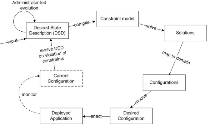
[image:4.612.143.479.303.504.2]Our general approach is to apply declarative and generative techniques to the deployment and management of distributed component-based software. Our goal is for application administrators to specify their deployment and management requirements for a distributed applicationdeclarativelyandconcisely in a high-level domain specific language. From this description, appropriate infrastructural elements are generated which are used to configure, deploy, monitor and manage the administrator’s distributed application.
Fig. 1.Approach Overview.
In Figure 1 we show an overview of our approach. The initial input to the process is a human readabledesired state description (DSD). A DSD is a specifi-cation of the hardware and software resources available, plus a set of constraints on the deployed software, and optionally an optimization function expressed in terms of the desirable characteristics of the deployment. The constraints address aspects such as component connection topology, component instance placement on physical hosts, and choice of component implementations/versions.
are drawn from a set of discrete domains, satisfying a set of given constraints. An example of a variable is an integerv1, the value of which should be assigned from the continuous domain of0..10. Constraints are typically binary relations, for example, the constraint that the value of one variablev1 is greater than the value of another variablev2. Solving a CSP requires finding a set of consistent value assignments for the variables that satisfies all of the constraints. Each domain-neutral candidate solution is re-mapped into the specification domain to produce a set of candidateConfiguration Description Documents (CDDs). A CDD describes a particular mapping of components to hosts and interconnection topology that satisfies the DSD. The most suitable candidate configuration is chosen andenacted to produce adeployment.
When a configuration is enacted,bundles are generated, encapsulating each component’s implementation; these are sent to and instantiated on the appro-priate hosts. Each bundle is an XML-encoded closure containing the code and data necessary to instantiate the component on a host. The bundle also includes custom probes and remote management interfaces to support monitoring and management of the deployed component. Implementations of these are gener-ated as a side effect of the DSD compilation process described above. The man-agement interfaces permit the manipulation of inter-component bindings during distributed application instantiation and maintenance.
As the application executes, it is monitored using the generated probes, which update a conceptually centralized (but physically distributed) model of the cur-rent configuration. This model is periodically compared to the desired state description. If it is detected that the model has ceased to satisfy the constraints specified in the DSD, the DSD is evolved to take account of the currently avail-able hardware and software resources, and the solving cycle is repeated. This may occur as a result of failures of components or hosts within the deployment. Evolution may also be initiated by a human administrator, allowing compo-nents in the distributed application to be upgraded, or new compocompo-nents to be introduced.
3.1 Specifying Desired State
DSDs are specified in the declarative Deladas language, similar in style to ar-chitecture description languages. The language’s universe of discourse includes interfaces,component types,templates,hosts andconstraint sets.
An interface specifies the contract for interaction with a particular service. It does not describe individual methods as in languages such as CORBA IDL. Instead, it defines a URI specifying a concrete language-level interface, and the location of its implementation.
Templates are used to factor out details that are common to multiple compo-nent types. A template defines provided and required interfaces, and, optionally, properties. A component definition may extend a template. Templates allow ab-stract, reusable, component-based architectural patterns and styles [11] to be described. Such patterns and styles typically represent well understood, tried and tested architectures for component-based systems. Patterns and styles may also describe rules of a regulatory or compliance nature, for example, to restrict where certain classes of computation can take place.
A host definition describes a physical machine capable of executing compo-nents, with a number of constant or dynamic properties.
A constraint [12] set contains predicates defined over various characteristics of a deployed application. When all the predicates hold, the application is said to be compliant with the constraint set, which constrains the manner in which the application is deployed—for example, with regard to the mapping of com-ponents to hosts, or the inter-component connection topology. Constraint sets are used to yield an initial satisfactory configuration for deployment, and also to detect desired state violations by a deployed application. The constraint al-gebra includes universal and existential quantifiers over components, templates and hosts, predicates over component connection topology, and expressions over properties.
We now introduce the syntax and expressibility of the Deladas language through a simple example application, a Maths service, which allows users to invoke simple mathematical operations. The service is implemented by one or more equivalent components, each of which in turn requires references to other components that provide multiplication and division services. Once the applica-tion has been deployed, a user can access it by locating one of the main service components and invoking its interface. Figure 2 shows an example DSD that describes the desired structure of the application.
Interfaces Three interfaces are declared:IMathsService,IMultiplicationService and IAdditionService. The implementation type of each interface is Java; each specifies a concrete interface in the form of a Java interface name, and the location of a definition of that interface.
Templates The templateMathsServiceTemplate is introduced to illustrate the language construct, though it is not strictly necessary for this example. The provides andrequires clauses state that the interface IMathsServiceis provided to clients, and that the interfaces IMultiplicationService and IAdditionService are required by the template. The template also declares the propertiesvendor andqueriesPerSecond.
interface IMathsService ( type = "java"
specification = "com.math.IMathsService"
implementation = "http://www.cs.st-andrews.ac.uk/deladas/mathsService.jar" )
interface IMultiplicationService ( type = "java"
specification = "com.math.IMultiplicationService"
implementation = "http://www.cs.st-andrews.ac.uk/deladas/multiplicationService.jar" )
interface IAdditionService ( type = "java"
specification = "com.math.IAdditionService"
implementation = "http://www.cs.st-andrews.ac.uk/deladas/additionService.jar" )
template MathsServiceTemplate ( provides interface IMathsService
requires IMultiplicationService multiplication, IAdditionService addition properties (
constant string vendor dynamic int queriesPerSecond )
)
component type MathsService extends MathsServiceTemplate (
implementation "http://www.cs.st-andrews.ac.uk/deladas/mathsService.jar" instantiate mathsServiceImpl with com.math.MathsService("hello")
satisfy IMathsService using mathsServiceImpl
bind multiplication with mathsServiceImpl.setMultiplyService() bind addition with mathsServiceImpl.setAdditionService() initialise mathsServiceImpl.init()
destroy mathsServiceImpl.shutdown() properties (
vendor = "CalculusSoftware"
queriesPerSecond providedBy mathsServiceImpl.qps() accuracy = 2
) )
component type MultiplicationService ( provides interface IMultiplicationService
implementation "http://www.cs.st-andrews.ac.uk/deladas/multiplicationService.jar" instantiate multServiceImpl with com.math.MultiplicationService()
satisfy IMultiplicationService using multServiceImpl )
component type AdditionService ( provides interface IAdditionService
implementation "http://www.cs.st-andrews.ac.uk/deladas/additionService.jar" instantiate addServiceImpl with com.math.AdditionService()
satisfy IAdditionService using addServiceImpl )
– The component mustsatisfy each of the provided interfaces declared by the template, in this case onlyIMathsService. This means that the component type must specify how the provided interfaces are implemented.
– The component will be provided with each of the required interfaces declared by the template, in this caseIMultiplicationService andIAdditionService.
– The component type must specify how values are associated with each of the properties declared in the template, in this casevendor and queriesPer-Second.
The first line in the body of the component type declaration specifies the lo-cation of a Java implementation. This implementation is consulted during com-pilationof the DSD to facilitate type checking and generation of appropriate glue code. Next, an instantiate construct specifies that each instance of the compo-nent type should instantiate the implementation class com.math.MathsService using the constructor taking the single given string parameter. The implementa-tion object is referenced asmathsServiceImplin the remainder of the declaration. The next line specifies that the provided interfaceIMathsServiceshould be imple-mented by that implementation object. The following two lines describe how the component binds to its required interfaces. The firstbind clause states that the interface multiplication, which is inherited from MathsServiceTemplate, should be bound to the implementation object by calling its methodsetMultiplyService().
Theinitialiseclause specifies that when a component is initialised the method init() should be called on the implementation object. The destroy construct specifies that the method shutdown() should be called on the implementation object before the component is destroyed. Finally, the component’s properties are defined. Constant values are specified for vendor and accuracy, while the value ofqueriesPerSecond is calculated dynamically by calling the methodqps() on the implementation object.
Figure 3 continues the DSD specification for theMaths service. This part of the DSD defines the available hosts and a constraint set.
This example illustrates the use ofhost templates to capture properties com-mon to a set of hosts. The host templatesBlade andCloudBladedefine different values for the host propertyspeed. Five instances of each host template are de-clared. The constraints specify that:
– every component of type MathsService must be located on a host with a speed of at least 2000.
– no component of typeAdditionService may have more than two other com-ponents connected to it.
– no host may have more than one component located on it.
– there must be at least three components of typeMathsService.
4
Implementation
host template Blade (speed = 1000) host template CloudBlade (speed = 3000)
host h1 extends CloudBlade (address = "server5.deladas.com") host h2 extends CloudBlade (address = "server6.deladas.com") ...
host h10 extends Blade (address = "server14.deladas.com")
constraintSet mathsServiceCons (
forall MathsService mathsComponent in deployment ( getHost(mathsComponent).speed >= 2000
) and
forall AdditionService additionComponent in deployment ( card(connections(additionComponent.IAdditionService)) <= 2 )
and
forall host h in deployment (card(getComponents(h)) <= 1) and
card(instancesOf(MathsService in deployment)) >= 3 )
Fig. 3.Constraints for the Maths Service.
4.1 Implementation of Compilation and Solving Mechanisms
A DSD contains the specification of the hardware and software resources avail-able, plus a set of high-level constraints on the deployed application. The DSD is compiled into a lower-level domain-neutral constraint satisfaction problem (CSP), which is then solved to yield a number of domain-neutral solutions. These solutions are then mapped back to the DSD domain to yield a number of can-didateconfigurations.
There is a wide gap between the level of abstraction used to model CSPs in tools such asJSolver and the abstractions used by an application administrator to express desired state descriptions in Deladas. Similarly, the result of solving a CSP, namely a set of assignments to integer and boolean variables, is far removed from the architectural configurations required for application deployment. Thus, a DSD must be compiled into a CSP, and a CSP solution must be mapped back into a deployment configuration.
Our solving framework has three main parts:
– A single general CSP, which models the general class of problem described by DSDs:
• the number of instances of each component type to be instantiated • the mapping of component instances to physical hosts
• the interconnection topology between component instances
– ACSP generator, which generates a new CSP for each DSD, based on the general CSP.
– An API providing a bridge between the constrained variables in the general CSP and the constraints expressed in a DSD.
General CSP The general CSP models the common parts of the configuration problem that must be solved for every DSD. It consists of a set of constrained variables and a set of default constraints over these variables. The CSP is the union of two sub-problems; the first models the number of instances of each component type and the hosts on which they are placed; the second models the component connection topology. The sub-problems are linked by constraints which reference each other.
Model I: Instance instantiation and placement This model contains con-strained variables representing all possible combinations of component and tem-plate instances on hosts. Each variable has a discrete domain of 0,1 with 1 indicating presence of an instance. For example, the model for the Maths ser-vice includes a constrained variable corresponding to host h3, component type MathsService and component count 4. If, in a solution, this variable has the value1, this indicates that the deployed application should locate 4 instances of MathsService on hosth3.
To improve solving efficiency, some basicpruning is performed to avoid cre-ating variables corresponding to impossible connections, for example where in-terfaces are incompatible. A number of default constraints are placed on the variables in this model, some of which also reference variables in Model I. These capture the following:
– a connection between two component instances may only exist in a configu-ration if both component instances also exist
– each of a component’s required interfaces must be connected to exactly one provided interface
API The API is intended to bridge between the problem-independent general CSP and the problem-specific CSP generated from the DSD. It provides a set of abstractions modelling entities in the DSD’s universe of discourse and a set of functions, operating over those abstractions, modeling Deladas functional-ity. Thus the API provides the abstractionshosts,components andtemplates. It also supports the abstractionspotential-instance, modeling a component instance that may be placed on a host, andpotential-connection, modeling a connection which may or may not exist between two components. Each abstraction sup-ports appropriate operations—for example,potential-instance permits the host, component and template type of the potential component it represents to be discovered.
The API functions permit sets of entities to be constructed, manipulated and constrained. The use of the API can be illustrated through the use of a simple example, utilizing four functions from the API: components(), card(), lessThanEquals() andaddConstraint(). The components() function accepts one parameter of typeHost and returns the set of allpotential-instances which may exist on that host in some configuration. The card() function accepts one pa-rameter which is a set of potential-instances and returns an expression which represents the cardinality of the provided set. The lessThanEquals() function returns aconstraint which constrains the value of anexpression to be less than or equal to a given integer. TheaddConstraint() function registers the provided constraint with the solver.
Using these functions a simple constraint set written in Deladas may be compiled into a problem-specific CSP extending the general CSP provided by the framework. The following Deladas example, specifying that the host h1 should have at most two components placed on it for execution:
// Deladas specification constraintSet structuralCons (
card(components(h1)) <= 2 )
// Java CSP specification
public class SpecializedCSP extends GeneralCSP { protected void structuralCons() {
addConstraint(lessThanEquals(card(components( getHostByName("h1"))),2));
} }
The generated Java class SpecializedCSP extends the class GeneralCSP, which implements the functions in the Deladas API, giving the generated code access to the API functions through Java inheritance. The host h1 referred to in the Deladas specification is manifested in the generated code by a look-up which extracts a set ofpotential-instance variables that may exist on hosth1 from the constraint model. The constraints operate over this set of potential-instances. The structuralCons() method adds a single constraint to the solver expressing the constraint expressed in Deladas. The API functions mirror those found in the Deladas specification and manipulate the data structures contained in the model to achieve the appropriate semantics. This syntactic trick enables bridging from the Deladas domain to the low-level domain of the constraint solver.
WhenSpecializedCSPis invoked, and some solution is found, the components assigned to the hosth1 may be determined by calling thecomponents()function described above. Configuration details may be extracted in a similar manner from the other types of variables. Thus the assignments made in the solver’s domain may be translated back into the high-level domain of the Deladas specification and a configuration description created.
CDD generation The solving framework generates a new CSP for each DSD. The generated classes are dynamically loaded into the solving framework and instantiated. The solver is then invoked to yield a set of solutions for the gen-erated CSP. As described above, solutions to the CSP must be mapped back into the problem domain to yield architecture configurations. This is achieved by iterating over each constrained variable in Model I & II that represents a po-tential instance or popo-tential connection. The assignment of the value of 1 to such a variable indicates that an instance or connection should be manifested in the deployment. Architecture configurations are represented as XMLConfiguration Description Documents (CDD).
deployment be considerably evolved. A better choice would be for the picker to select a candidate configuration which is closer to the current deployment, re-ducing the re-deployment required. The picker is configurable with respect to such policies.
Enacting a chosen configuration Enactment is the process of taking a chosen CDD and creating a running deployment. Enactment of a CDD is a complex task [14], requiring the following:
– Each component is packaged for transmission.
– Each component package is signed and sent to the appropriate hosts for execution.
– Upon arrival at a host, each component is verified to ensure that the signer has the appropriate rights to execute a component on that host.
– Once verified, each component is instantiated in its own address space1.
– Each component is provided with its required interfaces.
Once a CDD has been chosen, the components it describes must be deployed onto the appropriate hosts. This requires that the hosts have the appropriate infrastructure already deployed on them, and that the components are appro-priately packaged to support life-cycle management.
To provide a dynamic deployment capability, we have developed athin server architecture [13], which is used as a hosting platform for dynamically deploying components. Each thin server is essentially a light-weight daemon supporting a single operationfire(), which permits a bundle to be instantiated on it, provided that appropriate credentials are presented.
In order to facilitate deployment, each component is packaged into a bundle which may be sent to a thin server. To support life-cycle management, the bundle includes a Component Manager, which encapsulates the functionality required to perform deployment, undeployment, monitoring, initialization, destruction, querying of properties, and injection and substitution of service references re-quired by the component. This management functionality, exposed through a set of standard interfaces, is used to monitor and manage each component and thus collectively, the entire deployment.
Life-cycle management In order to execute correctly, components must be provided with references to the services on which they depend. The Deladas Runtime injects such references into components using setter injection [19]. To facilitate this, all inter-component references are made via an automatically gen-eratedsmart-proxy located in the same address space as the caller. If a compo-nent attempts to use a service before a reference has been bound, or during configuration evolution, the call blocks in the smart-proxy until a reference is
1 For the purposes of this paper we assume that each component executes in its own
injected. This mechanism decouples the management of the distributed system from the management of an individual component. The benefits are that com-ponents are not aware of which other comcom-ponents they are bound to, and that bindings between executing components can be dynamically evolved.
TheComponent Manager carries out a number of actions when instantiating its component:
– it creates appropriate instances of the component’s classes, as prescribed in the DSD;
– it instantiates and records a smart-proxy for each of the required services;
– it deploys each of the component’s provided services to make them available to external clients;
– if the DSD specifies one or more initialization methods, it calls them to run the component.
When a Component Manager is requested to undeploy its component, it first disables each of the component’s provided services, allowing any ongoing requests to complete. The component’s required services are disabled via their smart-proxies, preventing further outgoing calls from being made. Next, it calls the component’s destroy life-cycle methods declared in the DSD, to allow any necessary cleanup actions to be performed. The final action is to indicate to the thin server that it may terminate any processes required by the component.
5
Solver Performance
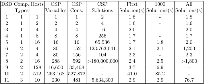
Table 1 shows the performance of the solver on a variety of DSDs expressed in Deladas. Performance data was gathered on a single 3GHz Pentium 4 work-station with 1GB RAM running Windows XP (SP2). Each DSD was compiled and solved three times to produce an average of the time required to find all solutions. The times indicated are the CPU time for the Deladas compiler, as reported by the classjava.lang.management.ThreadMXBean.
Column 1 contains the experiment number. Columns 2 and 3 contain the number of component types and hosts in the DSD. Columns 4 and 5 show the number of low-level variables and constraints contained in the generated CSP. Column 6 shows the number of different solutions to the CSP found by the solver. Columns 7-9 show the times to find the first solution, the first 1000 solutions, and all solutions.
The table shows the results for four groups of experiments, each demonstrat-ing different facets of the solver’s performance. In experiments 1-5, solutions for the deployment of a single instance of a single component type are found, with the number of hosts ranging from 1 to 16. Since every variable in the CSP has a domain of0,1, the solution space is exponential in the number of variables, as demonstrated in the numbers of candidate solutions found.
DSD Comp. Hosts CSP CSP CSP First 1000 All Types Variables Cons. Solutions Solution(s) Solutions(s) Solutions(s)
1 1 1 1 1 2 1.8 - 1.8
2 1 2 2 2 4 1.6 - 1.6
3 1 4 4 4 16 2.0 - 2.0
4 1 8 8 8 256 1.7 - 1.7
5 1 16 16 16 65,536 1.7 1.8 2.0
6 2 4 80 152 123,763,041 2.1 2.1 1,200
7 2 4 80 156 104 2.3 - 2.3
8 2 16 288 592 >180,000,000 2.4 2.5 >1,800
9 2 128 16,650 33,408 - 3.7 6.9
-10 2 512 263,168 527,872 - 41.0 85.2
[image:15.612.134.491.115.261.2]-11 3 10 230 481 5,634,300 2.9 2.9 76.7
Table 1.Solver Performance
the DSD permits up to two instances of every component type to be deployed on each host. Experiment 7 adds a further constraint that at most one component may be placed on any host. The additional constraint results in a very large reduction in the solution space, and consequently the time taken to find all solutions.
Experiments 8, 9 and 10 show the efficacy of the solver for larger numbers of hosts. From this it can be observed that it is impractical to wait forall candidate solutions to be found. However, in every case a first solution is found reasonably quickly. It may not be necessary to wait for all solutions to a DSD in order to receive an acceptable configuration. The use of optimization functions permits an administrator or a process to specify desirable aspects of a deployment. We anticipate that this will reduce the number of solutions a solver finds and increase thequality of those solutions. We intend to investigate mechanisms to trade off the number of solutions generated with the time taken to produce those solutions. One promising policy is to use optimization functions to specify the qualities of a good solution, and to specify an upper bound on search time—and select the best candidate configuration found within this bound. This work is ongoing.
Experiment 11 shows the time to solve theMaths service example. Despite having a realistic number of component types, hosts and constraints, 5 million solutions are found in a little over a minute.
6
Status and Future Work
We are concerned about the number of solutions that are generated by the constraint solver. This may be addressed by adding optimization functions to the DSD, permitting users to specify desirable characteristics of the deployment. Optimization functions permit the constraint solver’s search space to be reduced and allow the ranking of solutions.
We are currently building a distributed monitoring infrastructure to collect probe data and events occurring in the deployment. Our current framework has a set of standard probes which monitor aspects of a deployment such as component life-cycle (failure/shutdown), host resource levels and host failure. Assertion probes embodying constraints in the DSD ensure that assertions and constraints hold for the component or host they are monitoring. Such events will be reported to a Realm Manager responsible for monitoring and managing components and hosts. We observe that the runtime detection of constraint violations is a different activity to constraint solving. In the runtime currently under construction, the detection of violations will be the responsibility of the Realm Manager, which will dynamically invoke the constraint solver to determine new configurations as shown in Figure 1.
The utility of a configuration may be characterised both in terms of its fit for purpose at some instant and its ability to continue to perform well in the future. The latter may be expressed in terms of robustness and stability. A robust solution is one that requires minimal alterations in deployment in the face of changes in workload, server failure, network congestion, etc. The nature of these changes may be more or less understood depending on the nature of the deployment environment. Understanding the robustness of a solution gives a measure of the flexibility of the solution. Stability characterises the trade-off between the benefit of deploying a solution and the overall cost of deployment. In some cases, a (re)deployment may deliver high value, while in others the benefit may be outweighed by the cost.
In order for a solver to take account of stability, it would need to model both the cost of enacting a candidate configuration, and the benefit gained by doing so. To take account of robustness, the solver would need to be able to predict the likelihood of future events, and be able to model the impact of the reconfigurations required by those events.
7
Conclusions
We believe that automatic management of distributed application deployment will become essential as the scale and complexity of applications grow. This paper has outlined a framework to support the initial deployment and subsequent evolution of distributed applications in the face of perturbations such as host and link failure, temporary bandwidth problems, etc. The knowledge required for automatic management is specified in the form of a set of available hardware and software resources and sets of constraints over their deployment.
declarative specification. The approach we have taken involves the creation of a generic constraint satisfaction problem which describes the general problem of component placement and component interconnection. This general problem is specialised by generating a domain-specific constraint problem from the speci-fication. We have shown that constraint solvers can produce solutions quickly even in cases where the number of potential solutions are extremely high. We hypothesise that when optimisation functions are used the solution space will be considerably reduced.
We have also described how components can be generated that contain the infrastructure needed to control the entire component life-cycle including instan-tiation, destruction, monitoring and evolution. This is achieved by incorporating aComponent Manager along with non-invasive smart-proxies into the deployed code. The smart-proxies permit inter-component bindings to be changed within an executing components and hence the distributed application to be evolved.
We have sketched how constraint satisfaction may be used at run-time to control the evolution of applications. We are actively working on the next stage of implementation which will support constraint-led evolution of distributed ap-plications and hope to be able to report on this in the near future.
8
Acknowledgements
This work was supported by EPSRC Grants GR/M78403 Supporting Internet Computation in Arbitrary Geographical Locations, GR/R51872 Reflective Ap-plication Framework for Distributed Architectures and EP/C014782/1 Design, Implementation and Adaptation of Sensor Networks through Multi-dimensional Co-design.
References
1. Moriconi, M., Qian, X., Riemenschneider, R.A.: Correct architecture refinement. IEEE Transactions on Software Engineering21(4) (1995) 356–372
2. Oreizy, P., Medvidovic, N., Taylor, R.N.: Architecture-based runtime software evolution. In: International Conference on Software Engineering (ICSE 98), IEEE (1998) 177–186
3. Shaw, M., DeLine, R., Klein, D.V., Ross, T.L., Young, D.M., Zelesnik, G.: Ab-stractions for software architecture and tools to support them. IEEE Transactions on Software Engineering21(4) (1995) 314–335
4. Garlan, D., Monroe, R., Wile, D.: Acme: An architecture description interchange language. In: Conference of the Centre for Advanced Studies on Collaborative Research (CASCON’97). (1997) 169–183
5. Goldsack, P., Guijarro, J., Lain, A., Mecheneau, G., Murray, P., Toft, P.: Smartfrog: Configuration and automatic ignition of distributed applications. In: HP OVUA. (2003)
7. Hein, C., Ritter, T.: Global constraint checking at run-time. In: 8th International Symposium on Autonomous Decentralized Systems (ISADS ’07). (2007) 59–68 8. Ivan, A.A., Harman, J., Allen, M., Karamcheti, V.: Partitionable services: A
frame-work for seamlessly adapting distributed applications to heterogeneous environ-ments. In: HPDC ’02: Proceedings of the 11th IEEE International Symposium on High Performance Distributed Computing, Washington, DC, USA, IEEE Com-puter Society (2002) 103
9. Kichkaylo, T., Ivan, A., Karamcheti, V.: Constrained component deployment in wide-area networks using AI planning techniques. In: IPDPS ’03: Proceedings of the 17th International Symposium on Parallel and Distributed Processing, Wash-ington, DC, USA, IEEE Computer Society (2003) 3.1
10. Blythe, J., Deelman, E., Gil, Y., Kesselman, C., Agarwal, A., Mehta, G., Vahi, K.: The role of planning in grid computing. In Giunchiglia, E., Muscettola, N., Nau, D.S., eds.: ICAPS, AAAI (2003) 153–163
11. Garlan, D., Allen, R., Ockerbloom, J.: Exploiting style in architectural design en-vironments. In: Proceedings of the ACM SIGSOFT ’94 Symposium on the Foun-dations of Software Engineering. (1994) 175–188
12. Freuder, E.C., Mackworth, A.K.: Handbook of Constraint Programming. Elsevier (2006)
13. Diaz y Carballo, J.C., Dearle, A., Connor, R.C.H.: Thin servers - an architecture to support arbitrary placement of computation in the internet. In Piattini, M., Filipe, J., Braz, J., eds.: 4th International Conference on Enterprise Information Systems (ICEIS 2002), ICEIS Press (2002) 1080–1085
14. Dearle, A., Kirby, G.N.C., McCarthy, A., Diaz y Carballo, J.C.: A flexible and secure deployment framework for distributed applications. In Emmerich, W., Wolf, A.L., eds.: 2nd International Working Conference on Component Deployment (CD 2004). Lecture Notes in Computer Science 3083, Springer (2004) 219–233
15. Dearle, A., Kirby, G.N.C., McCarthy, A.J.: A framework for constraint-based deployment and autonomic management of distributed applications. In: ICAC ’04: Proceedings of the First International Conference on Autonomic Computing, Washington, DC, USA, IEEE Computer Society (2004) 300–301
16. : ILOG constraint programming. http://www.ilog.com/products/cp/(2008) 17. : MINION. http://minion.sourceforge.net/(2008)
18. : Cream: Class library for constraint programming in Java. http://bach.istc. kobe-u.ac.jp/cream/(2008)