Holistic electrical machine optimization for system
integration
Abstract— The power density of electrical machines required for transport applications has become a critical aspect and target of optimization. This paper looks at the development aspects of a multi-domain tool to aid for system-level optimization of electrical machines within next-generation high power-density applications. The electromagnetic, thermal and mechanical aspects are wholly integrated, thus enabling the optimization including the non-active mass. The implementation and overall architecture are described with the aim of deriving conclusions as to which SPM machine topology yields the maximum power to mass ratio.
Keywords— high power density, permanent magnet machines, multi-domain, optimization
I. INTRODUCTION
ith the globally increasingly stringent emissions legislations and fuel economy requirements, companies in the transportation sector are actively and intensely researching new technologies which often involve electrification and hence the use of electrical machines either for motoring or generation [1]. The performance targets in this type of work are various and depend a lot on the specific industry and application. For example ‘high power density’ is often a key phrase to distinguish new developments. In the land transportation industry, more specifically for road transportation systems, where volume is often highly constrained, the key power density metric is the power to volume ratio or [kW/L] [2]. On the other hand, for the aerospace industry, mass minimization, rather than volume, is critical and the key power density metric is the power to mass ratio or [kW/kg] with various numbers published to show achievements of particular developments, such as a recent 5 [kW/kg] for a light electric aircraft [3].
System architects working on the concept generation and system integration of the aforementioned more electric transport architecture often face a bottleneck when it comes to the electrical machine. Whilst comprehensive libraries of say, high speed bearings are normally available either through supplier input or in-house designs, for the high-performance electrical machines targeted in such work the available data is very limited.
Doing machine sizing in a manual manner for the range of options which the system architects want to investigate is too
much time consuming and impractical, while narrowing down the options risks in missing the system optima altogether. From the foregoing discussion clearly a tool is required to rapidly generate and assess optimal electrical machine solutions based on defined constraints taking into account the various sciences involved. This paper describes the development of such a tool for investigating options with the intent of maximizing the power density [kW/kg]. The targeted power density is determined as the developed power per total mass, including the mechanical parts required for the machine to operate. In the first part the logic and methodology behind the tool development is described. The tool is then implemented and used to compare the achievable [kW/kg] for various PM machine configurations for an 800kW alternator under an intense cooling regime.
II. REQUIREMENT ANDMETODOLOGY
At the early stages of transport electrification projects, the known data with which the system architects start is typically quite limited in nature. This often includes fundamental items, such as the power rating based on the vehicle size, a speed range based on existing turbines or engine designs, and a list of available cooling mechanisms. For the example in hand considered in this work, the power is 800kW with targeted speeds in the range of 3000 rpm to 15000 rpm. While the overall goal of maximizing the [kW/kg] is known, other items such as the volume, or aspect ratio of the machine are not specified and can be accommodated by the system designers who are often starting from a blank (flexible) design space.
Surface Permanent magnet (SPM) machines are known to be capable of achieving highest power-densities [1] for a single power and speed design point requirement. However, various types of SPM machines exist (inner rotor, outer rotor, dual-airgap, etc.) and it is not immediately obvious which of the aforesaid SPM configurations gives the best [kW/kg] if the volume is completely unconstrained.
In determining which type of SPM machine yields the best [kW/kg] and in doing optimization for mass minimization, it is important that the inactive mass is considered within the optimization procedure. By way of example, considering a previous high power density aerospace motor, the inactive mass is as high as 34% of the total machine mass. In many classical optimization approaches, the optimization is first
W
David Gerada
1, Dmitry Golovanov
1, Zeyuan Xu
1,2, Luca Papini
1, Michele Degano
1, He Zhang
2, Chris Gerada
1,2Power Electronics, Machines and Control Group, The University of Nottingham, UK1 Faculty of Engineering, The University of Nottingham Ningbo, China2
done on the electromagnetics, then a housing is designed around the optimized electromagnetic design. However, the housing can be a very significant proportion of the total mass and integrating the housing design with the overall machine [kW/kg] optimization has high potential for extra power density entitlement.
[image:2.595.305.548.52.284.2]Appropriate multi-domain tools which serve as the essential building blocks with which the [kW/kg] optimization is performed are required. To this end, for each SPM topology considered (i) electromagnetic, (ii) thermal, and (iii) mechanical analytical models are developed as shown in Fig.1.
Fig. 1. Multi-domain calculators as required for optimization
The arbitrary SPM machines are defined in terms of their geometries, constituent materials defined by their magnetic, mechanical and thermal properties, as well as the heat transfer coefficient and the coolant properties which also include the coolant inlet temperature and flow-rate. The following sections describe aspects of the multi-domain calculators implemented and adopted in the optimization tool.
III. ELECTROMAGNETICCALCULATOR
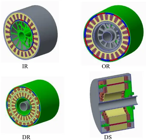
The analytical electromagnetic calculations require the description of the machine geometry. The considered machine topologies are shown in Fig. 2, which include single air gap machines – Inner Rotor (IR) and Outer Rotor (OR). Furthermore dual air gap machines are also considered namely the Dual Stator (DS) and Dual Rotor (DR) topologies. The electromagnetic model for the considered topologies is for a 3-phase single layer winding, with an additional such winding for the (DS) machine. The material selected for the stator structure consists of thin Cobalt-Iron laminations which represents a best-in-class material in terms of saturation flux density and high frequency core losses.
IR OR
[image:2.595.30.296.210.359.2]DR DS
Fig. 2. Considered SPM topologies for study
The main steps in analysing the performance of an arbitrary geometrical variation in meeting the design objectives are highlighted in Fig. 3 and described hereafter.
Fig. 3. PM machine analysis methodology
The no-load magnetic field evaluation is based on analytical models of machines with a Halbach array [4]. Under linear magnetic behavior of materials, the solution for the fundamental radial component of the flux density in air gap for the IR and OR topologies is given in [4]. The flux density estimation for the DS topology had been described in [5]. The flux density in the air gaps of the DR machine is evaluated by the introduction of auxiliary virtual PMs that represent the influence of ferromagnetic teeth on magnetic field. The total field in the air gaps can then be described as a sum of the real PM Halbach array and the reflected virtual PM.
The phase rms back-emf for the IR, OR and DS designs can be calculated by (1):
ܧ=ߨ√2݂ܹΦ (1)
whereܹis the number of turns per phase,݂is the electrical fundamental frequency, and Φ the flux per pole for the fundamental harmonic calculated from (2).
Φ=గܮܴ௦௧〈ܤ〉 (2)
[image:2.595.313.551.376.421.2]The back emf of the DS machine is calculated separately for the inner and outer stator winding. For the DR machine, the phase back emf is evaluated through the average value of magnetic flux in the inner and outer air gap (3).
Φ=ଶగܮ൫ܴ௦௧_௧〈ܤ_௧〉+ܴ௦௧_௫௧〈ܤ_௫௧〉൯
(3) A 3-phase single layer winding is adopted for comparing the various SPM topologies. Considering generation mode and assuming that machine current in ‘d-q’ axis is aligned with axis ‘q’ andIௗ= 0, the phase current can be expressed by (4) :
I=ଷఎ (4)
whereܲis the electromagnetic power, andߟis the efficiency.
Finally, the considered losses are divided as DC copper and on-load iron losses. For the on-load iron losses the on-load induction level ܤ௦ is the sum of flux densities produced by PM and armature current. The armature current flux density is evaluated by the approach described in [6].
IV. MECHANICALCALCULATOR
For the mechanical calculator, the input is the same arbitrary electrical machine geometry together with the mechanical properties of the constituent materials, namely the density and the yield strength. Based on these inputs, the mechanical calculator estimates the mass of the active materials (i.e. the mass of the copper, magnets and iron) and also sizes an appropriate housing around the electromagnetic geometry with the intent of estimating the non-active mass. Fig. 2 shows the typical housing sized around each SPM configuration. Apart from the bearings, the non-active parts in general consist of cylindrical shells and disks. The machines are assumed to be face-mounted. In determining the thickness of the aforesaid non-active disks and shells a minimum mechanical factor of safety of 2 is set on the material yield strength, together with a minimum thickness for practical manufacturing purposes. For all machine topologies, the housing shell and mounting disks are made of high strength aluminium, while the rotating shaft or cylindrical shells are made of high strength stainless steel. A cylindrical sleeve, made of carbon fiber, is used to retain the magnets. An oil-retention sleeve, made, of glass-fiber, is applied between rotor and stator to prevent coolant oil entering the air-gap.
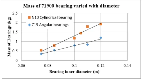
Bearings adopted at the drive-end and at the non-drive-end of the machine provide the rotational interfaces between the stationary and rotating components. For the drive-end a cylindrical bearing is selected, while for the non-drive-end a pair of back-to-back angular-contact bearings are used. The mass of the bearings for various shaft diameters is found from bearing catalogues and linear correlations between the bearing inner diameter and the mass of the bearing are derived based
[image:3.595.309.554.97.233.2]on the available bearing data. Fig. 4 shows the relations of bearing bore diameters and mass within the design range of the machines.
Fig. 4. Estimation of bearing mass as a function of bearing ID
From the data shown in Fig. 4, the following two correlations are derived for the cylindrical bearing (5) at the drive end and angular bearings (6) at the non-drive end :
ܯேଵ௬= 32.578ܦேଵ௬− 1.9589 (5) ܯଵଽ= 17.365ܦଵଽ− 0.9562 (6)
whereMandDare the mass [kg] and the bore diameter [m] of the bearing respectively. The subscripts ofN10cyland719ang correspond to the N10-series cylindrical bearings and 719-series angular contact bearings.
V. THERMALCALCULATOR
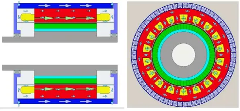
In this case the input is the same arbitrary electrical machine geometry as well as the thermal conductivities of the materials used. In addition to these the thermal calculation tool requires other inputs related to the coolant, namely the coolant thermal properties, such as the density, viscosity and conductivity, the coolant inlet temperature and the coolant flow-rates. Based on the aforesaid inputs, the thermal calculator estimates the temperatures at various locations within the electrical machine, namely at the coolant inlet and outlet, at the coil and end-windings, and at the stator core. In order to cool the machine efficiently and maximize the power density it is best to remove the heat as close as possible to the heat source. This significantly reduces the overall thermal resistances between the heat sources and the coolant to remove heat from the generator. Rectangular cooling channels are thus created in the slots, back iron and teeth of stator, as shown in Fig.5 for the case of the IR configuration, where most of the heat is generated by the copper and iron losses respectively. With this direct cooling concept, the thermal resistances at interfaces between stator core and housing, winding and slot wall are not critical any more for the machine cooling.
cooling concept is developed which constrains the coolant flow to the stator region. A cylindrical oil-can, located between the stator and rotor is designed to divide the machine into separate stator and rotor chambers. The stator chamber is filled with oil which flows through the channels from one side of the machine to the other. The rotor chamber is free of oil and this helps avoid high windage losses since the machine is running at high speeds. For the case of the dual-airgap machines two cans are used to create two separate oil-flooded regions (one for each stator).
Fig. 5. Intensive cooling strategy adopted for machines
A lumped thermal model is developed to simulate the cooling performances of the flow. Thermal resistances are added between each node based on the inner dimensions of the machine and the material thermal properties. The loss distribution within the machine is obtained from the electromagnetic calculations. The heat transfer coefficients are calculated using empirical correlations from literature as described by the following equations.
For laminar flow, Re<2300, in the channels [7]:
ܰݑ=
= 3.66 +
.ହோವ ಽ
ଵା.ସ(ோ)మ యൗ (7)
For turbulent flow, in the channels [7]:
ܰݑ=
= 0.023ܴ݁
.଼ܲݎ.ଷ (8)
whereܰݑ, andܴ݁are the Nusselt, Reynolds numbers of the flow. ܦ, andܮare the hydraulic diameter and the length of the channel. ܲݎ, ݇kf are the Prandtl number and thermal
conductivity of the cooling fluid.
The Reynolds number of flow is defined based on the hydraulic diameter of the cooling channel as follows [8]:
ܴ݁=
௩ (9)
The hydraulic diameter of a rectangular channel is defined by [8]:
ܦ=ଶ(ுାௐସுௐ ) (10)
Where in the above equations ܪ and ܹ are the height and width of the cooling channel,ܷis the average flow velocity in the channel andvis the kinetic viscosity of the fluid.
VI. OPTIMIZATIONMODEL
The preceding sections have described the development of the electromagnetic, mechanical and thermal calculators with defined inputs and outputs for the analysis of any arbitrary SPM machine geometry. Combining the three domains which are all scripted in Matlab is straightforward and acts as a multi-domain evaluation calculator which is readily used within the optimization problem where it is required to maximize the kW/kg which is the key performance metric for this study.
In order to determine the optimum design for the different SPM topologies presented in the previous section, a Genetic Algorithm which is embedded in the commercial optimization software modeFrontierTM is used. The optimum machine design is sought in a wide search space defined by the rotor speed and pole pairs which are limited by the maximum fundamental frequency permissible by the power-electronic converter.
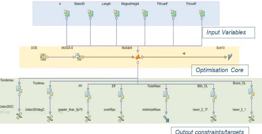
In other words, for any of the designs as described by the six characterizing parameters, modeFrontier passes the design to the Matlab scripts, which in turn assess and output the electromagnetic performance, thermal performance as well as calculate the total mass of the machine as described by the formulation of the preceding sections. This brings the setting-up of the optimization problem to the third and final level, highlighted in green in Fig.6., in which the Output Variables and Optimization Targets are defined. The problem in hand is single-objective in nature, and hence a single objective of minimizing the machine mass is defined. In achieving this target (i.e. finding the design which yields the desired power and speed with the minimum mass), a number of constraints are defined on the outputs. The first two constraints 'Tendsmax'
and 'Tcoilmax' relate to the thermal limitations, and ensure that
for any design to be considered feasible the temperature in the winding must not exceed a defined limit, which for the case in hand is set as 200°C corresponding to class C insulation. For a design to be considered feasible the power factor 'PF' and the efficiency 'Eff' must also be higher than defined thresholds (in this case power factor over 0.85 and efficiency over 98%) while the on-load tooth and core flux densities are limited to up to 2.1T. The final output variable constraints relate to the mechanical domain and impose a peripheral speed of up to 350m/s and a rotor factor of safety above 1.5.
VII. SPECIFIC POWER CHARACTERISTICS OF AN800KW INTENSIVELYCOOLED PERMANENT MAGNET MACHINE
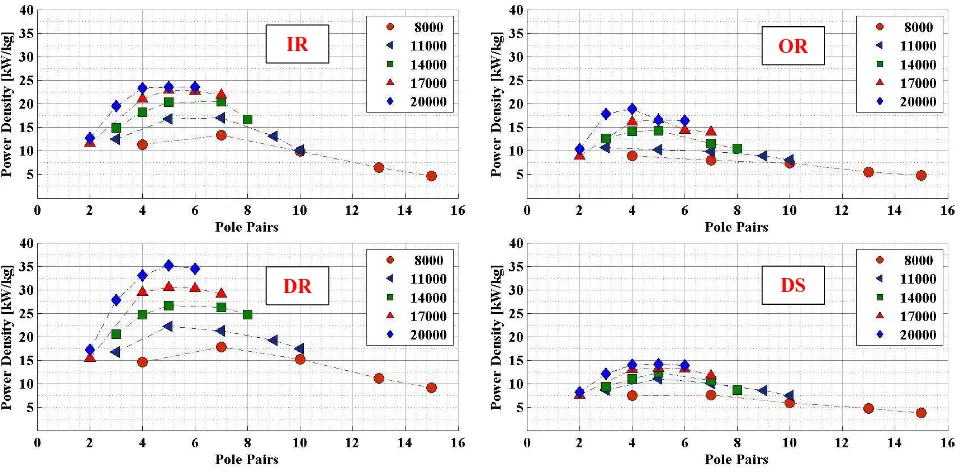
The four radial SPM machines of Fig.2., are optimized for a sequence of speeds in the range 8krpm to 20krpm for different pole numbers corresponding to an upper frequency limit of
1500 Hz. The coolant flow rate is 100 L/min at an inlet temperature 50°C. Fig.7. lays a clear map of the power-density [kW/kg] achievable by the different machine topologies. For a fixed power output the trend is for the power density to increase with the speed due to the lower torque-requirement. The power-density trend for all the PM machines generally increases with the number of pole pairs number until it peaks, after which the power density drops again. This is due to the increase in iron losses with the frequency increase. Also of interest, it is noted that for the power node targeted, high frequency machines are generally efficiency limited while the lower frequency machines are mainly limited by the thermal constraint. It is seen from this figure that a comparative trend exists between the considered electrical machine topologies. In general highest power density is achieved by the dual-rotor machine, followed by the inner rotor machine, the outer rotor, and the double stator.
VIII. CONCLUSION
[image:5.595.110.533.57.274.2]This paper has presented and described the essential building blocks and methodology in developing a rapid tool which can be used to explore wide search spaces and comparing different types of electrical machines. While the example focuses on power density [kW/kg], a similar integrated multi-domain approach can also be used to optimize for other goals typically sought in various industries such as [kW/L] and [$/kg] [9]. For the case of maximizing the power to mass ratio it has been shown by the use of the presented methodology that the dual-rotor PM machine achieves the best kW/kg and is thus a very promising topology in applications where the aforesaid metric is of importance.
REFERENCES
[1] D. Gerada et al., “High Speed Electrical Machines – Technologies, Trends and Development” in IEEE Transactions Ind. Electronics, pp2946-2949, vol61., Jan 2014.
[2] A. Mebarki, D. Gerada, and N.L. Brown, “Analysis of an Axial Flux PM Machine for Engine Integration”, inProc. Conf. Power Electronics Machines and Drives, PEMD 2014, pp.1-6, April 2014.
[3] “World record electric motor for aircraft”, Siemens AG press release, Jul 2016.
[4] Z.P. Xia, Z.Q. Zhu, and D. Howe, “Analytical Magnetic Field Analysis of Halbach Magnetized Permanent-Magnet Machines”, IEEE Trans. Magnetics, vol.40, no.4, pp.1864-1872, Jul. 2004.
[5] D. Golovanov, M. Galea, and C. Gerada, “2D Analytical Model for Dual-Stator Machines with Permanent Magnets”, in Proc. IEEE Ind. Elec. Conf, IECON 2016, pp.1560-1565, October 2016.
[6] Z.Q. Zhu, D. Howe, and C.C. Chan, “Improved Analytical Model for Predicting the Magnetic Field Distribution in Brushless Permanent-Magnet Machines”, IEEE Trans. Magnetics, vol.38, no.1, pp.229-238, Jan. 2002. [7] A. Bejian, Heat Transfer. Chichester : John Wiley & Sons, 1993. [8] S. Kakac, Handbook of Single Phase Heat Transfer. Chichester : John Wiley & Sons, 1987.
[image:6.595.61.541.77.313.2][9] Y. Duan, and D. Ionel, “A Review of Recent Developments in Electrical Machine Design Optimization Methods With a Permanent-Magnet Synchronous Motor Benchmark Study” in IEEE Transactions Ind. Applications, pp1269-1275, vol49.,Nov 2013.
Fig. 7. Comparison of power-density for different SPM topologies
OR
DS IR