Cooperative Relaying In Power Line Environment: A
Survey and Tutorial
AIYELABOWO, Peter, NOORDIN, Nor Kamaria, IKPEHAI, Augustine and
ADEBISI, Bamidele
Available from Sheffield Hallam University Research Archive (SHURA) at:
http://shura.shu.ac.uk/23892/
This document is the author deposited version. You are advised to consult the
publisher's version if you wish to cite from it.
Published version
AIYELABOWO, Peter, NOORDIN, Nor Kamaria, IKPEHAI, Augustine and ADEBISI,
Bamidele (2015). Cooperative Relaying In Power Line Environment: A Survey and
Tutorial. International Journal of Innovative Research in Computer and
Communication Engineering, 3 (5), 4224-4247.
Copyright and re-use policy
See
http://shura.shu.ac.uk/information.html
Sheffield Hallam University Research Archive
ISSN(Online): 2320-9801 ISSN (Print): 2320-9798
I
nternational
J
ournal of
I
nnovative
R
esearch in
C
omputer
and
C
ommunication
E
ngineering
(An ISO 3297: 2007 Certified Organization)
Vol. 3, Issue 5, May 2015
Cooperative Relaying In Power Line
Environment: A Survey and Tutorial
Peter O Aiyelabowo1, Nor Kamariah Noordin1, Augustine Ikpehai2
, Bamidele Adebisi2,
1
Department of Computer and Communication Systems Engineering, Faculty of Engineering, Universiti Putra
Malaysia, UPM Serdang, Selangor Darul Ehsan, Malaysia
2
Department of Electrical and Electronic, School of Engineering, Manchester Metropolitan University, Room E331,
John Dalton Building, Chester Street, Manchester.
ABSTRACT: Exchange of information is essential in any society and the demand for faster, cheaper, and secure communications is increasing every day. With other hi-tech initiatives like IPv6 and Internet-of-Things (IOT) already in the horizon, demand for broadband is set to escalate beyond its current level. Inherently laden in the challenges posed by this technology are fresh opportunities in terms of penetration of data services into rural communities and development of innovative strategies for more efficient use of the grid. Though still in its developmental phase/stage, Power Line Communication (PLC) has grown beyond theoretical fantasy to become a reality. The proofs are the readily available PLC systems that can be purchased off the shelfto achieve in-house networking and the much talked about, smart metering technology; generally regarded as the “new bride” in utilities industry. One of the biggest gains of PLC is its use of existing electrical cables, thereby eliminating cost of installation and maintenance of data cables. However, given that the power infrastructure was traditionally built to deliver electricity, data signals do suffer various forms of distortions and impairments as they transit it. This paper presents a tutorial on the deployed wireless system technique which is to be adapted to PLC scenario for the purpose of managing the available source energy for achieving reliable communication system. One of these techniques is the cooperative diversity. Its application and deployment in power line environment is explored. The improvement achieved through cooperative diversity in some PLC systems were presented along with the associated limitations. Finally, future areas of research which will further improve the reliability of PLC systems and reduce its power consumption during transmission is shown.
KEYWORDS: Power line communication (PLC), cooperation, power-line, node-selection, relaying,
amplify-and-forward and decode-and-amplify-and-forward.
I. INTRODUCTION
Over the years, demand for broadband applications such as education, gaming, entertainment, health, advertising, business and home networking has greatly increased and providers have explored various media (wired line and wireless) to meet it. This ever increasing demand for broadband access leads to the consideration of transmitting broadband data over power line network. Power Line Communication (PLC) is a technology aimedat transforming the electric power network into a communication highway, thereby introducing new vocabularies such as narrow and broad bands to power line. Narrowband/broadband information can be transmitted over its entire length to every device in use on the grid/network and to every user outlet [1]. PLC uses existing house wiring to provide data communication access. Driven by recent breakthroughs in communication engineering, PLC conveys data signals over electric cables by superimposing high frequency (data) signals over electricity signal (50/60Hz), thereby transforming the power line antiquated electricity-only channel of yesterday to dual purpose highway for electricity and communication signals. By taking advantage of the huge electricity infrastructure, a massive communication network can be formed; extending from the grid right into every socket in homes.
ISSN(Online): 2320-9801 ISSN (Print): 2320-9798
I
nternational
J
ournal of
I
nnovative
R
esearch in
C
omputer
and
C
ommunication
E
ngineering
(An ISO 3297: 2007 Certified Organization)
Vol. 3, Issue 5, May 2015
30 MHz[6], where 1-15 MHz is for outdoor applications and 15-30 MHz is for indoor applications. Its data rate is up to 300 Mbps [7]. The high-speed PLC architectures use modulation schemes such as Gaussian Minimum Shift Keying (GMSK), Direct Sequence Spread Spectrum (DSSS), and Orthogonal Frequency Division Multiplexing (OFDM). However, the OFDM modulation scheme is recommended due to its ability to withstand selective fadingmultipath and all sorts of interference [8].
Given that the power line infrastructure was traditionally built to deliver electricity, data signals suffer various forms of distortion and impairments as they propagate through it. Some of these impairments are caused by sudden turning “off” and “on” of electrical systems by in-house users or neighbors and changes in electrical configurations or background noise which is ever present in the channel.
A typical power network comprises of generation, transmission and distribution stages with three voltage levels; high voltage (HV), medium voltage (MV) and low voltage (LV)[9].
The realization of communication over the power line (electrical grid) requires basic PLC network elements. This is to allow signal conditioning for propagation over the power line as well as good reception.
There are basically two broad areas of applications of PLC; Outdoor and Indoor.
Outdoor PLC system includes Automatic Meter Reading (AMR); which is power meter reading over power-grid from homes to substation over the MV line (10kV) at a low data rate of 600bps – 2.4kbps. The outdoor applications are also referred to as narrowband, it involves one-way and bi-directional communications.
Indoor PLC is for home automation and Home Area Networking (HAN) over the Low Voltage (110 – 240V), achieving a data rate of 14 – 300 Mbps. Indoor PLC, sometimes referred to as Broadband over PLC (B-PLC) technologies,involves applications for voice, video, multimedia transmissions and networking.
As good, ubiquitous and promising as the PLC technology is, it is confronted with many challenges owing to the secondary use (as mentioned above) of the power line network. The effects of the impairments identified above on the PLC are: low signal power, high attenuation, multipath fading, interference, impulse noise, signal distortion and hidden nodes[10],[11]. Amongst these challenges, impulsive noise and attenuation/multipath fading poses the most impairment to its performance.
The signal attenuation in Power Line Network (PLN) according to[12] amounts to 100dB/km and 10dB/km for low and medium voltage networks respectively. This loss of signal is premised on the following ([13], [10]);
Time of the day Operating frequency
Length of channel (distance between transmitter and receiver) Branched line’s length
Terminal load impedance. Ambient condition
The implication of these factors on the power line channel summarily presents the channel as an unpredictable channel. Additionally, power cables suffer from considerable frequency-dependent attenuation that increases with high frequencies and can be severe for long-distance communications. Moreover, impedance mismatching is commonly present in PL networks causing enormous reflections of the signal which in turn gives rise to multipath fading.
Therefore, to reliably use power line for communication purposes, there is need for system that can predict or measure performance of the channel in terms of throughput, packet loss, and access delay.
II. POWER LINE (PL) CHANNEL MODELAND NOISE SCENARIO
ISSN(Online): 2320-9801 ISSN (Print): 2320-9798
I
nternational
J
ournal of
I
nnovative
R
esearch in
C
omputer
and
C
ommunication
E
ngineering
(An ISO 3297: 2007 Certified Organization)
Vol. 3, Issue 5, May 2015
frequency dependent attenuations. Sequel to the nature of the power line channel, it presents unfavorable channel properties characterized by noise and high data attenuation.
Two models are prominent in the PL channel's model, they are Philipp's echo model [18] and Zimmermann and Dostert's [19] model. In both models the transfer function of the power line channel is modeled following the top-down approach.
Philipp came up with a conceptual sketch of the PLC channel and derived an expression for the transfer function in equation (1)
f H =
N
i i 1
.ej2fi(1)
Where N is the number of possible signal flow paths, each having been delayed by time
i is multiplied by a complexfactor
i.
ias represented in the equation, is the product of transmission factor and reflection factor. This model is inadequate for describing the characteristic of the PL channel due to its non-consideration of attenuation effects during the propagation of signal.Zimmermann and Dostert’s model is a development on Philipp's model, the channel accounts for attenuation of the signal flow.
They obtained the model's transfer function as presented in equation 2, where gi is a factor used for describing weight
of the individual’s path. It is also a product of transmission and reflection factors over a path length of di (i is the path's
number). The knowledge of gi and diis necessary for the determination of the input channel responses.
f H =
N
i i
g
1
.
i k o f de
1 .. p
i
v d f j
e
2
(2)
The first exponential presents the attenuation factor while the second exponential is a description of the echo scenario. The factor vp is the signal's propagation speed. Parameters αo, α1 and k are used to model the attenuation factor. These
parameters αo (offset attenuation), α1 (increase of attenuation) and k (exponent of attenuation) are obtained from
measurements of the magnitude of the frequency response.N represents the number of taps on the line.
ISSN(Online): 2320-9801 ISSN (Print): 2320-9798
I
nternational
J
ournal of
I
nnovative
R
esearch in
C
omputer
and
C
ommunication
E
ngineering
(An ISO 3297: 2007 Certified Organization)
Vol. 3, Issue 5, May 2015
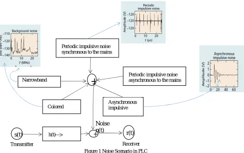
[image:5.595.62.559.170.482.2]
Figure 1 Noise Scenario in PLC
Colored Background Noise: These are various sources of white noise with different amplitudes at different portions of the frequency band which does not belong to the other identified classes of noise. They are usually characterized by relatively low power spectral density (PSD) which is inversely proportional to frequency [23].
Narrowband Noise: This noise occurs at narrow fractions of the frequency band with high Power Spectral Density (PSD). It is a partial overlay to the background noise. Its source is mainly from broadcaster's signals at short, medium and long waves as well as the amateur radio and it appears in the frequency domain as sharp peaks of noise amplitudes. This noise can also appear at low frequencies, its occurrence is traceable to the switching of electrical devices such as television sets, power supply fluorescent lamps or computer screens.
Periodic Impulsive Noise Asynchronous to the Mains Frequency: This noise occurs for only a short duration with relatively low amplitude, hence, they are usually considered as background noise. Its repetition rate is between 50 KHz to 200 KHz. It is often caused by switching power supplies.
Periodic Impulsive Noise Synchronous to the Mains Frequency: This is of short duration, having its PSD varying inversely as frequency. Its repetition rate is of 50 Hz or 100 Hz. The power supplies which operates concurrently with the mains cycle is responsible for this noise. This is inherent in power converters found in dimmers and rectifiers using diodes.
Asynchronous impulsive noise: This impulsive noise duration is from some microseconds upwards to a few milliseconds and they arrive randomly, they are often referred to as 'burst noise'. Its PSD can sometimes be about 50 dB above the background noise ([20],[24]). All kinds of switching operations such as household appliances, electric motors etc., are responsible for this noise. This noise differs from its periodic counterpart in its time of occurrence and its duration and is adjudged the probable most difficult to deal with [21]. The impulsive noise is the major source of interference in PLC [25].
Periodic impulsive noise synchronous to the mains
Colored noise Narrowband noise
Asynchronous impulsive
Periodic impulsive noise asynchronous to the mains
+
s(t)
h(t)+
H(f)
r(t)
Transmitter Receiver
ISSN(Online): 2320-9801 ISSN (Print): 2320-9798
I
nternational
J
ournal of
I
nnovative
R
esearch in
C
omputer
and
C
ommunication
E
ngineering
(An ISO 3297: 2007 Certified Organization)
Vol. 3, Issue 5, May 2015
III. POWER LINE CHANNEL CAPACITY ENHANCEMENT
As described earlier, the harsh nature of the power line channel is a barrier to easy transmission of data from the source-point (transmit) to the end-point(destination). Therefore a procedure of identifying a clean path to the destination and then allocating more of the source energy to the path/channel is necessary, thus judiciously and efficiently managing the limited available transmit power. This will enhance reliability in the PLC channel while not adding any structure to the system.
To achieve good performance of the power line network for digital signaling, some techniques are deployed to improve its output in the face of all these impairments. These techniques are described in this section.
Repeaters: A repeater is an electronic device with the sole responsibility of receiving a signal and retransmitting it at a higher level or higher power against an obstruction. In digital communication systems, repeater receives digital signals on optical transmission medium or an electromagnetic and regenerate the signal along the next leg of the medium. This regeneration and retransmission is carried out at different frequencies, this is called frequency translation.
In PLC networks, repeaters can be used to extend coverage. The PLC network is divided by the repeater into segments and the segments separated by the use of different frequency bands or time slots. Thus, the originated length of the PLC network is reduced by the network segmentation, then lower signal power can be used for transmission in-line with the electromagnetic compatibility requirement.
Pen An et al. [16] presented an analysis of the application of repeaters in PLC access network. They presented a PLC network with one head end (HE), six repeaters (REP) and fifteen customer premises equipment (CPE). The HE serves as the source while the CPE is the destination. Simulation results shows that increase in number of repeaters increase correspondingly the total saving time and the spatial reuse degree in the whole PLC network.
Cypress [26] also developed a repeater algorithm that can overcome the limitation of distance between the nodes and the loading ends of a PLC system. A device, CY8CPLC20 was programmed with the repeater algorithm. This solution by cypress does not disconnect the power line but enables every node to act as a repeater, eliminating the need for separate devices. The use of repeaters in PLC, though yielded channel maximization, increases overhead cost owing to the cost of purchasing the repeater equipment.
Multiple Inputs Multiple Outputs (MIMO): Multiple input multiple output (MIMO) is a communication technology developed with the expectation of high data rate with transmission rate close to 1 G bits/s and high speed link offering good quality of service (QoS). It uses more than one transmit (Tx) antenna to route a signal over the same frequency to more than one receive antennas. This high rate in terms of channel capacity (C) and quality is characterized by minimum probability of error (Pe). MIMO family members include, single input multiple output (SIMO), which
implements only one antenna in its input and more than one on its output. It is often referred to as transmit diversity. When multiple antennas are at the input and only one is at the output, multiple input single output (MISO) results. It is used in advanced cellular networks and is often called receive diversity [27]. MIMO in PLC can be is referred to as Multi-Emitting/Multi-Receiving ([28],[29]). Antennas in wireless systems are replaced by the wires in PLC which technically means that the highest number of input/output available in PLC is 3 for a three phase network
Hashmat et al.[30] demonstrated that in the case of in-home offering multiple feed ports comprising of three wires, phase, neutral and protective earth, more channel capacity can be achieved than in the two wire system (SISO) implemented. The three wires in the PL channel provide three possible ports, P-N, P-PE and N-PE for differential signal transmission and reception. The Kirchhoff's circuit law limits the three differential feed into two, therefore the Authors performed three 2x2 MIMO. Measurements on each of the six branches possible were conducted.
ISSN(Online): 2320-9801 ISSN (Print): 2320-9798
I
nternational
J
ournal of
I
nnovative
R
esearch in
C
omputer
and
C
ommunication
E
ngineering
(An ISO 3297: 2007 Certified Organization)
Vol. 3, Issue 5, May 2015
Lothar et al. [32] modeled the PLC MIMO as does the other Authors. In their own case two ports were established at its input and four ports at the output. These four ports are made up of three differential reception ports and the fourth, a common mode (CM) path. By this arrangement, a 2x4 MIMO scheme was set-up. Eigenbeamforming and Alamouti MIMO schemes were applied in the PLC MIMO scenario.
Further research on the application of MIMO in PLC showed that MIMO application for in-home PLC has effectively and significantly increased the throughput and yielded better coverage. Cross talk arises in these schemes owing to the electromagnetic coupling between the adjacent wires, this limits the effectiveness of MIMO for PLC applications. The techniques described above achieves better data rates in the various systems where they were deployed but with tradeoffs for installation cost and interference introduction.
IV. NETWORK (NODE) COOPERATION
Cooperative diversity in wireless systems in presented in this section. A brief description of the basic principles involved is given, this it to give a general overview of cooperative diversity which could be applied in a PLC system.
MIMO scheme as discussed in the previous section, is a technique aimed at achieving high data rates in wireless communication systems, where performance is impaired by fundamental limitations. MIMO is an alternative method for improving the channel capacity order than increasing transmits power, bandwidth and/or applying powerful error control coding (ECC)[33]. As discussed, there are several realizations of MIMO, but all centered on using multiple antennas at either transmitter or receiver ends and even at both ends, considered in terms of diversity, as spatial diversity. Adiversity scheme that has improvedwireless device performance and can easily improve PLC device performance is the cooperative diversity. In this scheme, the advantage of MIMO spatial diversity is implemented, this time not with multiple antennas (emitter in the case of PLC), but a single antenna networked nodes, arrange themselves in proper order to form a virtual antenna array.
The nodes associated with each source serves as helper, having received the transmission from the source, re-transmits it to the destination. Spatial diversity is achieved by the cooperation of neighboring nodes in the sharing of their antennas. So the cooperative network has three major nodes as discussed below;
Source: It is required that this node should be aware that its transmission has been forwarded to the relaying node.
Relay: This operates any of the three transmission protocols to be discussed later or a hybrid of the two.
Destination: This node attempts to decode the packet after reception from the source and/or relays, decoding until data from source and relay is received. In the former, after destination receives data from source, an information regarding the necessity of a cooperation transmission could be sent to both the source and relay nodes. In the second case, the signals from source and relay nodes are combined, based on the combination technique implemented at the destination node.
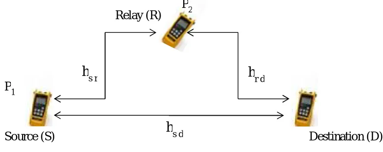
General Principle of Cooperative Diversity
The three major nodes in cooperation in a cooperative network are as shown in figure 2, where transmission at the source node is done with power P1 and power P2 for transmission at the relay node([34],[35]). These nodes could be a
mobile, ad hoc network or cellular networks. The operation of the setup below is in two phases. In the first phase, called the 'broadcasting', the source transmits the signal to both the destination node and the relay node. The received signals at the destination and relay nodes in this phase is as expressed as [36],[37] and [35].
sd
y
=P
1h
sdx
+n
sd (3)sr
y
=P
1h
srx
+n
sr (4)WhereP1 is the transmitted power at the source node, x is the transmitted information symbol, and nsd andnsr are the
ISSN(Online): 2320-9801 ISSN (Print): 2320-9798
I
nternational
J
ournal of
I
nnovative
R
esearch in
C
omputer
and
C
ommunication
E
ngineering
(An ISO 3297: 2007 Certified Organization)
Vol. 3, Issue 5, May 2015
but modelled as multipath fading in PLC. The modeling of nsd and nsr follows a zero-mean Gaussian random variable
with a variance of No. (cooperation in PLC is described in section 6)
[image:8.595.103.492.215.370.2]
Figure 2 Nodes in Cooperation
In the second phase, called 'cooperation', the signal received by the relay in the first phase is forwarded to the destination through an orthogonal channel after it has passed through a processing determined by the chosen transmission protocol. The signal received at the destination in this phase is given by [36],
rd
y
=h
rdq
y
sr +n
rd (5)where the function, q(.), depends upon the protocol implemented at the relay node at the power P2.
There are two major cooperation strategies;
Fixed Cooperation (relaying) Strategy: The division of the channel resources between the source and the relay nodes is predetermined (fixed). Any transmission protocol can be chosen for the information processing at the relay. The easy implementation of this cooperative strategy is its advantage over the other, but it suffers from bandwidth inefficiency, since the channel is shared equally between the source and the relay even when the source-destination path (direct line) is not affected by fading [36].
Adaptive Cooperation (relaying) Strategy: The bid to avoid the inefficiency in the fixed cooperation motivates the development of this strategy. The decision to choose any path for signal transmission from source to destination is governed by some specified conditions. Selective and incremental relaying are the two most common techniques that implements adaptive cooperation strategy. The SNR is the operation parameter in the selective relaying, therefore, any of the chosen protocol in the relay is applied if the received signal's SNR exceeds a certain threshold in forwarding the information from the relay to the destination, else it is idle [38]. In incremental relaying, the relay only transmits its received signal if the destination node does not receive the source message correctly. When the destination receives the source signal correctly, an acknowledgement signal is sent to the relay through a feedback channel from the destination to the relay. Hence, if the first phase transmission to the destination is correct, there will be no need for the second phase (cooperation) transmission, the source will then transmit new information. But in the event of incorrect reception at the destination, the relay can implement any of the cooperative transmission protocol to cooperate with the destination node [36]. The incremental relaying has the best spectral efficiency because the relay is not always transmitting.
Source (S)
Destination (D)
Relay (R)
P
1P
2h
r dh
s d
ISSN(Online): 2320-9801 ISSN (Print): 2320-9798
I
nternational
J
ournal of
I
nnovative
R
esearch in
C
omputer
and
C
ommunication
E
ngineering
(An ISO 3297: 2007 Certified Organization)
Vol. 3, Issue 5, May 2015
Cooperative network can be deployed in either a single relaying or multiple relaying configurations. Single relaying involves the use of only one relay node, (dual-hop), between the source and the destination nodes, while in multiple relaying, more than one relays are implemented in between these two nodes.
The relay nodes can operate in full-duplex or half-duplex modes. In the full-duplex mode, the relay transmits and receives signal simultaneously on the same frequency. The implementation of the full-duplex in principle involves the cancellation of the relay's self-interference from the received signal. This approach, in practice, is not robust for low cost radio.
In half-duplex mode, transmission and reception are required to be carried out via orthogonal channels, the relay can use different time slot to transmit and receive. Source node transmits to the relay and destination in the first time slot, while the relay transmits its processed received signal to the destination in the second time slot. The same mode is implemented in PLC environment, different time slots for source to relay and relay to destination transmission ([39],[40],[41])
V. COOPERATIVE TRANSMISSION PROTOCOLS
This section gives an insight into the various transmission protocols deployed in communicationsystems for cooperation. The principles of common transmission protocols are described. Itserves as a foundational information for application in the PLC environment. Adaptation of some of these protocols to PLC will be discussed in section 6.
The signals transmitted from the source node and received at the relay nodes passes through some processing's. These processing's are provided for by the cooperative transmission protocol at the relay node. These protocols include, Amplify-and-Forward (AaF) ([42],[43]), Decode-and-Forward (DaF) [44], Compressed-and-Forward (CaF) and Code Cooperation ([45], [46],[47]).
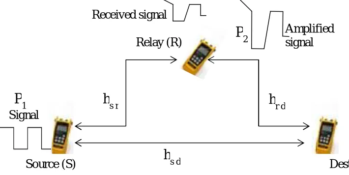
Amplify-and-Forward (AaF) Single Fixed Relaying
In AaF protocol, the signal received at the relay passes through amplification and then retransmitted to the destination. This protocol is appropriate for relay stations that have minimal computing power. Figure 3 illustrates the AaF configuration.
[image:9.595.95.450.530.708.2]Figure 3 Amplify-and-Forward Cooperation
In the broadcasting phase, the transmitting node (source)sends signal to both the relay and the destination nodes, these signals is given as [38],
Source (S)
Destination (D)
Relay (R)
h
r dh
s dh
s rSignal
Received signal
Amplified
signal
P
1
ISSN(Online): 2320-9801 ISSN (Print): 2320-9798
I
nternational
J
ournal of
I
nnovative
R
esearch in
C
omputer
and
C
ommunication
E
ngineering
(An ISO 3297: 2007 Certified Organization)
Vol. 3, Issue 5, May 2015
sr
y
=P
1h
srx
+n
sr (6a)sd
y
=P
1h
sdx
+n
sd (6b)P1 being the transmitted power at the source and x, the transmitted symbol.
At the relay node, amplification of the received signal is performed to equalize the effect of the channel fades between the source and the relay. Thus, a factor, , which is inversely proportional to the received power is used to scale the received signal at the relay. This factor is denoted as,
= o sr
N
h
P
P
2 1 2 (7)where P2 is the transmitted power at the relay.
The amplified version of the source signal is then advanced to the destination in the cooperative phase. The received signal at the destination during the cooperation phase is given in equation
rd
y
= o srN
h
P
P
2 1 2 sr rdy
h
+n
rd(8)
substituting (6a) into (8) yields,
rd sr rd o sr
rd
h
h
x
n
N
h
P
P
P
y
2 1 2 1 (9)where rd sr rd
o sr
rd
h
n
n
N
h
P
P
n
2 2 . Assuming that nsr and nsd are independent, then the equivalent noise,
rd
n
is a zero-mean complex Gaussian random variable with variance
o o sr rd N N h P h P 1 2 1 2
2 . Where
h
rdis the channelcoefficient from relay to the destination and
n
sdis an additive noise.The destination node then combines ysd and yrd following the choice of its combination technique.
A major drawback of this protocol is that as a result of signal amplification, inherent noise in the signal is also amplified, leading to reception of two independently failed version of the signal. Thus, the destination is provided with all the information the relay was able to observe through AaF, leaving the decision for the destination. Therefore, energy and time spent on cooperative transmission will be a waste if the SNR of the signal received by the relay is low.
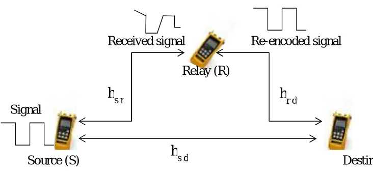
Decode-and-Forward (DaF) Fixed Single Relaying
Decode-and-Forward (DaF) is another cooperative network protocol. In this protocol, the relay node detects the source data, decodes and encodes it, and then re-transmits it to the destination.
ISSN(Online): 2320-9801 ISSN (Print): 2320-9798
I
nternational
J
ournal of
I
nnovative
R
esearch in
C
omputer
and
C
ommunication
E
ngineering
(An ISO 3297: 2007 Certified Organization)
Vol. 3, Issue 5, May 2015
[image:11.595.91.457.172.341.2]
Figure 4 Decode-and-Forward Cooperation
then the transmitted signal form the relay to the destination will be x' if the relay's decoded signal is x'.
In the broadcasting phase (1st phase), same signal is transmitted to both relay and destination nodes as in AaF (eqns. (6a and 6b)). In the cooperation phase (2nd phase), the signal received by the relay node, after passing through decoding and encoding, is transmitted to the destination. This signal is given as,
rd
y
=
2h
rdx
+n
rd (10)If the transmitted signal correctly decoded at the relay node, β2 = P1, else β2 = 0.hrd is modelled as a complex Guassian
random variable with variance
rd2 . The noise term is also modelled as a zero-mean complex random variable with variance No.The destination through the information of the channel coefficients hsd(between source and destination) and hrd
(between relay and destination), detects the transmitted symbols by jointly combining the received signal ysd from the
source in eq. (6a) and yrd from the relay in eq. (10).
In the event of a retransmission of an incorrect signal by the relay, decoding at the destination node will be a wasted effort. In this case the diversity achieved is only one (1), as the system's performance is confined to the worst link from source-destination and source-relay.
Compress-and-Forward (CaF)
Unlike DaF and AaF where the relay transmits a duplicate of the received signal, in compress-and-forward, the relay transmits a compressed and quantized version of the received signal [48]. The destination then performs the reception of the combination of signals from the source node and the compressed version from the relay node.
The process of quantization and compression at the relay is simply representing each received signal as a sequence of symbols, this is called coding. For instance, say the symbols are binary digits (bits), by decoding the sequence of bits received at the destination, an estimation of the compressed signal/message can be obtained. In this decoding operation, the received bits are mapped into a set of values that estimates the transmitted signal/message. Reconstruction of the original data relying solely on the compressed information is difficult, if not impossible, hence, the destination needs information about the compressed data to be fully able to reconstruct the original information. So it is expedient for the destination to acquire the necessary information from the source transmission and/or the other relays transmission. Some authors sometimes refer CaF as , Estimate-and-Forward, Quantize-and-Forward or Observe-and-Forward [48].
Source (S)
Destination (D)
Relay (R)
h
r dh
s dh
s rSignal
ISSN(Online): 2320-9801 ISSN (Print): 2320-9798
I
nternational
J
ournal of
I
nnovative
R
esearch in
C
omputer
and
C
ommunication
E
ngineering
(An ISO 3297: 2007 Certified Organization)
Vol. 3, Issue 5, May 2015
This protocol suffers some form of attenuation and noise introduced by the process of bits mapping which often comes with distortion.
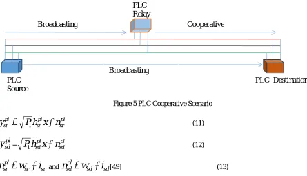
VI. PLC COOPERATIVE NETWORK SYSTEM
A typical PLC cooperative system is as shown in figure 5. Just as in cooperative activity in wireless systems, the source and the relay node transmits P1 and P2 powers respectively at both transmissions scenarios. The two transmission
scenarios are broadcasting (direct) and cooperative as depicted in figure 5. During the first transmission (broadcasting), the received signals at both the PLC destination and relay nodes is as shown in equation (11)&(12).
[image:12.595.62.507.288.544.2]
Figure 5 PLC Cooperative Scenario
pl sr pl sr pl
sr
P
h
x
n
y
1
(11)pl sd
y
= sdplpl sd
x
n
h
P
1
(12)sr sr pl
sr
w
i
n
andn
sdpl
w
sd
i
sd[49] (13)Where P1 is the PLC source transmit power and
pl sr
n
andn
sdpl are the noise at the source-destination and source-relayPLchannels respectively.
n
sdpln
srpl are constituted of colored background noise and impulsive noise, which has a Gaussian amplitude and Poisson arrival (see section 2). w represents the colored background noise and i, impulsive noise.pl sd
h
andh
srpl are multipath channel between source-destination and source-relay paths respectively. These channels are modeled as depicted in equation (2).In the cooperative transmission, the PLC relay modem processes the received signal as prescribed by the adopted cooperative protocol, then forwards it through its channel to the PLC destination nodes. The signal received at the destination node at this second transmission is given as
pl rd
y
= rdplpl sr pl
rd
q
y
n
h
P
2(
)
(14)rd rd pl
rd
w
i
n
(15)PLC Relay Broadcasting
Broadcasting
Cooperative
PLC Source
ISSN(Online): 2320-9801 ISSN (Print): 2320-9798
I
nternational
J
ournal of
I
nnovative
R
esearch in
C
omputer
and
C
ommunication
E
ngineering
(An ISO 3297: 2007 Certified Organization)
Vol. 3, Issue 5, May 2015
P2is the transmitted power at the PLC relay node and q represents the cooperative protocol deployed.
PLC Amplify-and Forward Cooperation
This process in the PLC is similar to the one described in wireless communication system, except for the channel and the inherent noise. The signal received at both the destination and the relay nodes in the broadcasting phase is as
described in equations (11) and (12). The relay received signal is made stronger by a factor
pl[41]x pl sr pl
N
h
P
P
2 1 2
(16) i wx
N
N
N
(17)Where
N
x is the noise PSD in the power line channel a sum of the PSD’s in the AWGN and the impulsive noises.The amplified signal is then transmitted to destination in the second transmission phase (cooperative). The signal received at the destination during this transmission will be;
pl rd pl sr pl rd pl pl
rd
h
y
n
y
andn
rdpl
w
rd
i
rd (18)i pl rd pl sr pl rd x pl sr pl
rd
h
h
x
n
N
h
P
P
P
y
2 1 2 1 (19) pl rd pl sr pl rd x pl sr plrd
h
n
n
N
h
P
P
n
i
2 1 2 (20)Where
n
rdpl is the noise in the power line channel from the relay to the destination andh
rdpl is the power line channelcoefficient between relay and destination modem. The destination node will then combine the two signals,
y
sdpl andpl rd
y
following the chosen combining technique. Although this protocol has a drawback of amplifying noise along with signal, which can be unhealthy for power line communication, mitigating the noise before amplification will present a better performance.PLC Decode and Forward Cooperation
In this protocol as described in section 6, the relay modem decodes and re-encodes the signal received. Its channel and noise are as described in PLC amplify and forward. After decoding and encoding at the PLC relay node, the signal is
ISSN(Online): 2320-9801 ISSN (Print): 2320-9798
I
nternational
J
ournal of
I
nnovative
R
esearch in
C
omputer
and
C
ommunication
E
ngineering
(An ISO 3297: 2007 Certified Organization)
Vol. 3, Issue 5, May 2015
pl rd pl rd pl pl
rd
h
x
n
y
2
(21)Where
2pl=P1if relay correctly decodes the transmitted signal andpl 2
=0 if otherwise.h
rdplandn
rdpl are modeled as in PLC amplify and forward.Various techniques can be implemented for the combination of the signals at the destination end. They include;
Equal Ratio Combining (ERC): It assigns equal weight to the different paths of signal reception and sums up all received signals together. Equation (21) describes the output in an ERC receiver,
k
i pl id pl
y
y
d
1
(22)
In the scenario of only one (1) relay,
pl rd pl sd pl
y
y
y
d
(23)Fixed Ratio Combining (FRC): Incoming signals in this method are weighted with a constant ratio before adding them up. Its output at the destination is as described in equation (23) ;
k
i
pl id id pl
y
q
y
d
1
(24)
Where qid is the parameter describing the weight of the incoming signal. When a single relay is implemented, equation
(23)is written as
pl rd rd pl sd sd pl
y
q
y
q
y
d
*
(25)Signal to Noise Ratio Combining (SNRC): This provides intelligent weighting of the incoming signals. SNR is used to characterize the quality of the link, it is then used to weight the received signals.
Maximum Ratio Combining (MRC): This technique assumes that the receiver knows perfectly the channel's phase shift and attenuations. Each input signal is then multiplied by its corresponding conjugated channel gain.
Enhanced Signal to Noise Ratio Combining (ESNRC): In this technique, data from better quality incoming channels are selected while other incoming ones are ignored.
The commonly implemented combining technique is the Maximum ratio combining (MRC).
VII. NODE (RELAY) SELECTION
In multiple relaying cooperative system, selecting the relay that offers the best path to the destination has been found to enhance system performance. This section describes the selection procedure and the different types of method deployed in relay selection. This knowledge is necessary for implementation in the PLC system.
ISSN(Online): 2320-9801 ISSN (Print): 2320-9798
I
nternational
J
ournal of
I
nnovative
R
esearch in
C
omputer
and
C
ommunication
E
ngineering
(An ISO 3297: 2007 Certified Organization)
Vol. 3, Issue 5, May 2015
Relay selection is vital to the success of any cooperative diversity system. For a relay to be selected for transmission, it must be in the source transmission range to support the nodes communication. The process of selecting a relay may be governed by the following questions;
How many relays are needed to be selected for good/efficient transmission between the source and destination nodes?
How fast should the relay selection be?
When should a relay(s) be selected, before or after the direct transmission? Which node is responsible for the relay selection?
What principle of selection should be implemented?
Providing answers to these questions will lead to an appropriate relay selection suitable for efficiency in cooperative diversity.
In a cooperative network, where communication pair is established under the assumption that the energy and time needed for the cooperative scheme does not exceed the non-cooperative scheme, best relay selection plays a vital role in achieving more efficiency than using all achievable relays [51]. In this context, the resource will be well managed, since it will be shared between two nodes (source and best relay) and not between source and multiple relays. In fact, same diversity order will be achieved in both scenarios, since if the best relay fails, it is obvious that all the relays will fail too.
The rate of relay selection is expected to be fast enough to support communication attempt, so that relay selection will not delay or skip communication. A time varying channel condition and dynamic networks requires a faster relay selection to cope with the frequency of the variation for a good cooperative diversity. When the coherence time and topology information are not matched, as in the case of dynamic environments, it is required that the frequency of relay selection follow each transmission attempts, i.e. relay is selected for every transmission event [52].
Time of relay selection, whether before or after direct transmission is cogent in relay selection decision. It can be classified into two categories, pro-active relay selection ([52],[53]) and re-active relay selection ([54],[55]).
In pro-active relay selection schemes, relay selection is done before direct transmission. At the beginning of the direct transmission phase, the cooperating relay is known to the source and destination nodes. In fact, the source may be aware of the selected relay's cooperating gain and can implement the information to choose a transmission rate that is appropriate. Higher priority is given to cooperative transmission than direct transmission in pro-active relay selection scheme.
Relay(s) is chosen after direct transmission in re-active relay selection scheme. If direct transmission is through to the destination, the relay selection is skipped. In this scheme, for a node to be selected, it must meet two requirements; received packets from the source and must be in the transmission range between the source and destination. The selection is done briefly before the cooperative transmission and focuses solely on the relay-destination channel. Direct transmission is prioritized in this scheme. Since all the nodes overhear the source in this scheme, overall energy consumption is high.
The parameters used for the selecting a particular relay node for cooperation can be summed-up as;
Instantaneous SNR of both source-relay and relay-destination links – used to minimize the outage probability. Average SNR – equivalent to a distance based selection scheme.
Energy consumption/residual energy level – maximum overall lifetime of the network.
Overall transmission time – between cooperative transmission and non-cooperative transmission.
Relay Selection Algorithms
ISSN(Online): 2320-9801 ISSN (Print): 2320-9798
I
nternational
J
ournal of
I
nnovative
R
esearch in
C
omputer
and
C
ommunication
E
ngineering
(An ISO 3297: 2007 Certified Organization)
Vol. 3, Issue 5, May 2015
performance and lower power consumption, its challenging nature is traded off for this advantage. Some of the prominentperformance indices used for the selection of a particular relay or a set of relays are, channel state information (CSI), signal-to-noise ratio (SNR) and packet error rate (PER). Therefore, relay selection does not center on source-destination performance alone, but done in such a way that the overall system performance is taken into consideration.
Relay selection algorithms can be classified into three major categories [56];
1. Group selection: This is aimed at achieving a pre-defined performance level. This selection of the relay is done before direct transmission.
2. Proactive selection: Selection in this category is done during the transmission time. The selection can be performed by the source node, destination node or the relay node itself.
3. On-demand selection: In this category, relay is only selected when it is requested (needed). Most often, it happens when the direct link (channel) condition is seriously faded below a specified threshold.
A further classification of relay selection mechanism can be done in terms of the interaction between the network entities. This includes;
Opportunistic relay selection scheme Cooperative relay selection scheme
Opportunistic relay selection scheme is characterized by local measurements. It can be subdivided into three [56];
1. Measurement-based relay selection 2. Performance-based relay selection 3. Threshold-based relay selection
These three opportunistic relay schemes all follow proactive approach.
In the cooperative selection scheme, the exchange of information between the cooperating nodes is requested. The two subdivisions are;
Table-based relay selection: selection of one or two relays is based on the information kept on a table in the source node.
Contention-based relay selection: this involves the selection of a variable number of relays.
Therefore in all, the relay selection algorithm can be summarized into six categories. These six categories of relay selection will be described.
Measurement-based relay Selection Algorithm
Since this algorithm is based on local measurement of instantaneous channel conditions, it does not require any topology information. The best relay amongst n number of relays is selected. The source-relay and relay-destination channels conditions are estimated by each potential relay using the request-to-send (RTS) and clear-to-send (CTS) commands. The source-relay-destination channel expected performance serves as a benchmark for the estimation of the CSI between source-relay and relay-destination, which is based on their amplitudes fading. The relays, after they have estimated their CSI's, sets a transmission timer to a value inverse of the CSI estimated value. The relay that qualifies for selection is the relay whose timer expires early, it is then selected and it transmits a short duration packet [57]. As soon as the qualified relay sends this packet, the other relays overhear it and they will back off the listening mode.
ISSN(Online): 2320-9801 ISSN (Print): 2320-9798
I
nternational
J
ournal of
I
nnovative
R
esearch in
C
omputer
and
C
ommunication
E
ngineering
(An ISO 3297: 2007 Certified Organization)
Vol. 3, Issue 5, May 2015
Performance-based Relay Selection Algorithm
The most suitable relay in this algorithm is based on performance criteria, such as delay and energy efficiency [58]. The operation of this algorithm is in two phases. In the first phase, the source node transmits the level at which performance is required, while in the second phase, the relays estimates their channel conditions alongside with their performance levels. The estimated performance level is then compared with the required performance level for the selection of the qualified relay. This algorithm can be implemented in the PLC since transmission is done through the relay that meets the required level.
Threshold-based Relay Selection Algorithm
This algorithm relies on certain set threshold values to minimize the number of qualified relays, so as to also minimize the accruable channel estimation overhead. The algorithm has dual identity, can belong to opportunistic or cooperative. Its operation involves two phases. Each relay equatesits received signal quality with a set threshold of either SNR or BER [56]. Only the relay that satisfies the threshold requirement qualifies for the selection process.
In the case where SNR is used as the threshold parameter, the relay with maximum lower rate SNR in both source-relay and relay-destination links is selected.
The two major challenges faced by this algorithm are its complexity which results when m number of relays meets the threshold requirement and the inability of the algorithm to react to variations in the channel conditions, since the values are fixed. This is a bad news in PLC where the channel is known to be time varying.
Adaptive Relay Selection Algorithm
This algorithm only proposes relay selection performance when it is needed in high probability. At times, due to variations in channel conditions, the direct probability of error will so much decrease that there wouldn't be need for relay operation, in this scenario, the adaptive relay selection scheme is applicable. In the first phase, the destination checks for equality of its received signal from the source node with a pre-determined threshold stored in it. A request for relay operation is made only if the signal's quality is below that threshold, otherwise, it is not requested [59].
Maintenance of the optimality of the threshold value at the destination is required in this algorithm in order to combat the fast varying channel condition. This can be accommodated in PLC as channel variations are not so pronounced.
Table-based Relay Selection Algorithm
The concern of this algorithm is to decrease the effect of the time taken to select a specific relay on the overall transmission time. It follows a cooperative relay selection process.
The source node serves as storage of two channel state information. The first, being the CSI between links and their potential relays and the second, the CSI of the links from the potential relays and potential destination. The instruments used for the gathering of these CSIs are RTS/CTS frames and the information collected from the overhead transmissions. Then, the source node selects a relay by looking up in a table. So, a node is selected as a relay if the sum of the transmission over the source-relay and relay-destination links time is less than the transmission time over the direct link to the destination. Willingness to cooperate is initiated by cooperate-RTS signal sent by the source to the relay(s) and same from the relay to the destination. The destination then sends cooperate-CTS if the initiated cooperation is beneficial to both links.
When the nodes are moving, table-based relay selection algorithm presents a degradation problem. Since the concern of this algorithm is also desired in the PLC and its nodes are not moving, it can be suitable for PLC application.
Multi-hop Relay Selection Algorithm
ISSN(Online): 2320-9801 ISSN (Print): 2320-9798
I
nternational
J
ournal of
I
nnovative
R
esearch in
C
omputer
and
C
ommunication
E
ngineering
(An ISO 3297: 2007 Certified Organization)
Vol. 3, Issue 5, May 2015
overhearing the transmission over the identified network area, the potential relays decides whether or not to relay the overheard signal to the destination, even in the event of the absence of direct link packet transmission between source and destination. Thus, the source of the information received at the relay may be traced to three sources; from the source node, from the other relays or from an intermediary node (router). Furthermore, the signal received at the destination may be from more than two independent sources as in other schemes, but three, owing to the three sources of relay signal reception (source node + router + selected relays).
Therefore, at the destination node, the diversity of the cooperation is increased, leading to an increase in robustness and performance.
This scheme suffers high cost, owing to the extra overhead in network incurred by the transmission of redundant information and the process of collecting routing information.For the limited allowable transmit power in PLC, this algorithm may not be suitable, since transmission would be made to all relay nodes while some of these relay channels will suffer degradation, thus attenuating the signal further.
VIII. RESOURCE (POWER) ALLOCATION
In PLC transmit power spectral density (PSD) is regulated [60], thereforeits assignment on the different paths (channel) during propagation is an important activity. This section unveils the various processes of power allocation algorithm in communication systems for efficient and reliable transmission of signal from source to destination nodes. This information is necessary to facilitate its adaption in PLC for efficient signal transmission.
The performance of each relaying node, anchoring on how resources, such as time, bandwidth and transmission power is allocated to them, determines the end-to-end (e2e) performance of the system [61]. In optimum resource allocation, the system assigns/allocates different fractional bandwidth, time slots and transmission power between each pair of nodes. Some nodes in the cooperative network can serve as an energy harvesting unit.
The two major questions that arises in cooperative networks are;
i. How much of the source power should be set aside for direct transmission? ii. How much power should be earmarked for the cooperative transmission?
These questions are answered by the power allocation criteria formulated or deployed. Many power allocation schemes in cooperative networks are optimized with the followings;
Approximate symbol error rate, subject to transmission rate and power constraints. Target SNR requirements.
Overall system capacity (throughput).
Outage probability, subject to total power constraints. General closed-form symbol error rate.
Diversity.
Outage probability of mutual information. Total energy consumption.
Achievable information capacity.
Network capacity in terms of achievable mutual information.
There are different ways of distributing a node transmission power between other nodes in a cooperative transmission. These methods will be described briefly.
Centralized Power Allocation Scheme
ISSN(Online): 2320-9801 ISSN (Print): 2320-9798
I
nternational
J
ournal of
I
nnovative
R
esearch in
C
omputer
and
C
ommunication
E
ngineering
(An ISO 3297: 2007 Certified Organization)
Vol. 3, Issue 5, May 2015
to the controller by the relay candidates. Hence, the controller network has the knowledge of the CSI and heterogeneous power constants at various nodes. The controller then computes the optimum power allocation parameters for each link/channel. The nodes then adjusts their transmit power following the results of the controller network's computation received. Some of the common types of centralized power allocation are described below.
Equal Power Allocation (EPA)
In this scheme, the distributing node allocates equal amount of power to the partnering nodes [63]. As such, the knowledge of all the links is not required. This is the chief advantage of the scheme, because it will lead to reduction in the network overhead.
In a network involving many source-destination pairs, the relay allocates the same amount of power, Pri to each user
[64]
i i N
i s
ri P h
N
P 1
1
2
. (26)Where N is the number of sources whose signal can be detected at the relay, Ps, the power at the source (all sources
have same power), hi is the source-relay link gain,
i= 22 1 2 1 i i R h P
is the power splitting fraction and η, denotes the
energy harvesting efficiency.
Sequential Water Filling Based Power Allocation Strategy
This is another efficient strategy that maximizes the destination's success if the global channel state information is available at the relay (in the context of multi-source-destination pairs). For successful detection at the destination for a DaF multi source-destination pair network, the relay needs to allocate a transmission power expressed as [64],
2 2 arg , 1 2 rd R et t i h
P (27)
to the i-th destination.
Where hr d is the relay-destination channel gain and R is the targeted rate.
When n sources deliver their information to the relay, the relaying transmission power required can be ordered as;
2 1 2 1 2 d R h ≥ ... ≥ 2 2 1 2 nd R h (28)
The water filling power allocation strategy processes includes;
the destination with the strongest channel is the first to be allocated with the power
2 2 1 2 nd R h
, if the total power
in the relay is greater than or equal to
ISSN(Online): 2320-9801 ISSN (Print): 2320-9798
I
nternational
J
ournal of
I
nnovative
R
esearch in
C
omputer
and
C
ommunication
E
ngineering
(An ISO 3297: 2007 Certified Organization)
Vol. 3, Issue 5, May 2015
the relay serves the next channel with the strongest channel gain with the power 2
) 1 ( 2
1
2
d n Rh
if possible.This power allocation continues in that order until all the destinations have been served or there is not enough power left at the relay. The probability of having m successful receivers among n destinations can be expressed as;
m i m i r R r Rn
N
P
i
n
g
P
i
n
g
1 1 1 2 2 2 2,
)
1
(
1
2
,
)
1
(
1
2
Pr
<
>
, (29)The average number of successful destinations can be determined by summing all the possible choices of m and n.
Distributed Power Allocation
Distributed power allocation scheme is a solution to the high computational burden inherent in the centralized power allocation scheme. It reduces the computational burden drastically since no controller network is required. The individual nodes are responsible for the calculation of their power allocation factor and it is done at the nodes. In distributed approach, the knowledge of partners CSI and some initial values for their power allocation factors are assumed at the nodes. The node then optimizes its power allocation based on these assumptions after which it then broadcasts the optimization results to its partners. The source-relay, relay-destination links CSI of the connected source is available at each relay of Nr, making it possible for a communicating link to compute the capacity of that particular
link.
Moreover, partners' allocation factor can be deduced by a node from the mean SNR it received from the partner. With the real power allocation of the neighboring modes serving as a reference, a last transmitting node can optimize its power allocation factor. Therefore the new power allocation of M-1 partners serves as reference for power allocation optimization for the first node and these continues over the number of required or desired iterations.
A type of a distributed power allocation scheme traditionally used to model resource allocation problems is the game theory. The three basic components in a game model are the set of player (participants), an action/strategy to be performed by each player, and the benefit accruable to each player for performing the action. The players in cooperative network are the nodes, which may be source node, which transmits data to the destination, or relay nodes, which help in enhancing the source data transmission to the destination. The action/strategy that these nodes perform are decision making on forwarding of data, channel/power allocation and route participation to certain destination node in the network. Benefit(s) or payoffs can take several forms, determined by the system's parameters. It could be transmission rate, bandwidth utilization, power consumption or lifetime. Game theory is a study of strategic decision making, a study of mathematical models of conflict and cooperation between intelligent rational decision makers. There are two main branches of game theory, cooperative and non-cooperative.
Non-cooperative game theory generally deals with the interaction of individuals, having good sense of judgment, with each other for the purpose of achieving individual goals. Game theory can be used to achieve a distributed channel resource allocation scheme when the channel allocation problem is modelled as a non-cooperative game ([65],[66]). Decisions are made by individual rational nodes independently to maximize usage without concern for the effects of their choice on the other nodes (players). Thus, any cooperation is self-seeking, even, selfish network may not cooperate.
ISSN(Online): 2320-9801 ISSN (Print): 2320-9798
I
nternational
J
ournal of
I
nnovative
R
esearch in
C
omputer
and
C
ommunication
E
ngineering
(An ISO 3297: 2007 Certified Organization)
Vol. 3, Issue 5, May 2015
In cooperative game, nodes come together in joint action, characterized by binding commitments which is analyzable. These nodes then communicate amongst each other. The two major categories of cooperative game are coalitional games and bargaining game. Network nodes in coalitional game, for the purpose of improving their payoffs, cooperate with each other by forming cooperative groups called coalitions. This group is often described in terms of characteristic function, and it tells of the result achieved by each group when an individual node coordinates their actions. In bargaining game, there is an opportunity for all network nodes to reach an agreement that guarantees mutual benefit. A concept that plays vital role in determining a unique Pareto-optimal solution in cooperative game is the Nash bargaining solution (NBS). It models the activities of bargaining based on six intuitive axioms. Nodes on the power line network cannot form a joint action because of the tree topology deployed on the PL channel. Applying the cooperative game on the PLC may have some difficulty owing to its topology.
Auction Theory
Auction, is a type of sale where the price is not set or arrived at by negotiation, but is attained/discovered through a process of competitive and open bidding. It is always conducted by an Auctioneer, who coordinates the sale of the resources based on the bills from the potential buyers (bidders). Bidders submits their bids for a specific resource at an announced price(s), then the resources is allocated <