Combining software cache partitioning and loop tiling for
effective shared cache management
KELEFOURAS, Vasileios <http://orcid.org/0000-0001-9591-913X>,
KERAMIDAS, Georgios and VOROS, Nikolaos
Available from Sheffield Hallam University Research Archive (SHURA) at:
http://shura.shu.ac.uk/19064/
This document is the author deposited version. You are advised to consult the
publisher's version if you wish to cite from it.
Published version
KELEFOURAS, Vasileios, KERAMIDAS, Georgios and VOROS, Nikolaos (2018).
Combining software cache partitioning and loop tiling for effective shared cache
management. ACM Transactions on Embedded Computing Systems, 17 (3).
Copyright and re-use policy
See
http://shura.shu.ac.uk/information.html
shared cache management
Kelefouras Vasilios, Keramidas Georgios, and Voros Nikolaos
One of the biggest challenges in multicore platforms is shared cache management, especially for data dom-inant applications. Two commonly used approaches for increasing shared cache utilization are cache parti-tioning and loop tiling. However, state-of-the-art compilers lack of efficient cache partiparti-tioning and loop tiling methods for two reasons. First, cache partitioning and loop tiling are strongly coupled together, thus ad-dressing them separately is simply not effective. Second, cache partitioning and loop tiling must be tailored to the target shared cache architecture details and the memory characteristics of the co-running workloads. To the best of our knowledge, this is the first time that a methodology provides i) a theoretical foundation in the above mentioned cache management mechanisms and ii) a unified framework to orchestrate these two mechanisms in tandem (not separately). Our approach manages to lower the number of main memory accesses by an order of magnitude keeping at the same time the number of arithmetic/addressing instruc-tions in a minimal level. We motivate this work by showcasing that cache partitioning, loop tiling, data array layouts, shared cache architecture details (i.e., cache size and associativity) and the memory reuse patterns of the executing tasks must be addressed together as one problem, when a (near)- optimal solution is requested. To this end, we present a search space exploration analysis where our proposal is able to offer a vast deduction in the required search space.
Categories and Subject Descriptors: []
CCS Concepts:rTheory of computation→Shared memory algorithms;rSoftware and its
engineer-ing→Compilers; Retargetable compilers;
Additional Key Words and Phrases: cache partitioning, loop tiling, page coloring, data array layouts, memory management
ACM Reference Format:
ACM Trans. Embedd. Comput. Syst., , Article (March 2018), 25 pages.
DOI:http://dx.doi.org/10.1145/0000000.0000000
1. INTRODUCTION
Efficient shared cache utilization in multicore platforms represents one of the most performance and energy critical problems, especially for data dominant applications. First, uncontrolled data contention occurs among different tasks, because all the cores can unrestrictedly access the entire shared cache memory [Tam et al. 2007]. Second, when the total size of the data structures of the executing application is larger than the cache size and the data are accessed more than once, the data are loaded and reloaded many times from the slow and energy demanding main memory. A well-studied direc-tion to address the first problem is to rely on software (SW) cache partidirec-tioning tech-niques, called page coloring [Tam et al. 2007] [Ding et al. 2011] [Kim et al. 2013] [Ye et al. 2014]. A fruitful approach to circumvent the second problem is by employing com-piler level techniques such as loop tiling [Bondhugula et al. 2008b] [Kandemir et al. 2009] [Kim et al. 2007a] and data array transformations [Sung et al. 2012] [Henretty et al. 2009]. However, when applying the above optimization techniques, most of the shared cache architecture details and data reuse patterns of the (co-)executing applica-tions are not appropriately taken into consideration. Most importantly, all the related approaches address the two above problems separately.
mentioned techniques that minimize the number of accesses to main memory; in this way, the search space for identifying the correct configuration parameters is decreased by many orders of magnitude. More specifically, we showcase that if the transforma-tions employed in this paper are included in an iterative compilation process (in order to test all different related implementations/binaries), the compilation time will last about 1037 years. On the other hand, using the proposed methodology the
compila-tion time lasts from some minutes to some hours in a commodity processor. Thus, an efficient point in the search space can be found in a reasonable amount of time.
The major contributions of this paper are the following: i) for the first time, shared cache partitioning, loop tiling, and data array layout transformations are addressed theoretically but most importantly in a single framework, i.e., as one problem and not separately, ii) cache partitioning and loop tiling are addressed by taking into account the last level cache (LLC) architecture details and the memory characteristics of the co-running applications, iii) a direct outcome of the two previous contributions is that the search space (to fine-tune the above memory management techniques) is decreased by many orders of magnitude.
In the context of this work, we make the following assumptions. We assume that the applications have already been parallelized into independent tasks and that all the extracted tasks have been mapped onto the cores at compile time (the mapping is done either randomly or by the user). As such, no extra tasks are allowed to enter for execution at runtime. In addition, our model assumes a fixed number of tasks mapped into a core. The output of our framework is the (near)-optimum tile sizes of the loop kernels (within the tasks), the shared cache partition sizes, and the data array layouts. The goal is to reduce, to the extent possible, the number of main memory accesses keeping at the same time the number of arithmetic instructions (introduced due to loop tiling transformation) at a minimal level. Additionally, the proposed methodology can be applied iteratively for all the different mappings between tasks and cores, so as the best mapping is calculated, i.e., which tasks should run on each core. Finally, it is important to note that instead of partitioning the shared cache at the task level, we use per-core cache partitioning which is proved to be more efficient (the reasoning behind this design decision is further explained in Section 3).
The problem of finding the number of main memory accesses for each tile set is the-oretically formulated by exploiting the special memory access patterns of each studied task. In particular, one mathematical equation for each loop kernel is generated. This equation provides the number of main memory accesses while the tile sizes serving as the independent variables of the equation. The goal is to end-up with specific tile sizes that minimize the above equations, i.e., minimize the number of main memory accesses taking into account all the co-running tasks. However, the solution offering the minimum number of main memory accesses does not always provide the mini-mum execution time of a task due to the additional inserted arithmetic/addressing instructions required to support the loop tiling transformations. In our methodology, among the different implementations achieving a main memory access value close to the minimum, we select (theoretically) the one providing the fewest number of arith-metic instructions.
The evaluation of the proposed methodology is based on detailed, cycle and power accurate simulations, using the gem5 [Binkert et al. 2011] and McPAT [Li et al. 2009] simulators, assuming the x86 instruction set. The selected benchmark suite consists of eight well known data dominant loop kernels taken from [Pouchet 2012]. Our obtained evaluation results are reported in terms of compilation time, main memory accesses, arithmetic instructions, achieved performance and energy consumption.
The remainder of this paper is organized as follows. In Section 2, the related ap-proaches are provided and the concept of page coloring is introduced. The proposed methodology is described in Section 3 while experimental results are presented in Sec-tion 4. Finally, SecSec-tion 5 concludes this paper.
2. RELATED WORK AND BACKGROUND 2.1. Software Cache Partitioning
A static cache partitioning policy (as assumed in this work) predetermines the amount of cache blocks allocated to each task(s) and/or core(s) prior to execution. Typically, cache partitioning mechanisms require specialized hardware support in order to mod-ify the placement/replacement strategy of the underlying cache taking into account the task and/or core id. To alleviate this restriction and also make our methodology appli-cable to commodity processors, our cache partitioning mechanism is based on software (SW) cache partitioning, also known as page coloring [Tam et al. 2007] [Kim et al. 2013] [Ding et al. 2011] [Ye et al. 2014]. Leveraging the fact that the shared LLC (the target cache level in this work) is typically physically indexed, the page coloring technique controls the virtual to physical mappings used by individual tasks [Tam et al. 2007]. The key to the page coloring technique lies in the mapping between cache entries and physical addresses [Kim et al. 2013].
2.2. Related Work
et al. 2007], [Kulkarni et al. 2009], or statistical techniques [Haneda et al. 2005] to decrease the search space. However, by employing previous approaches, the remaining search space is still big enough. The end result is that seeking for the optimal config-uration is impractical even by using modern supercomputers. This is evidence by the fact that most of the iterative compilation methods use either low compilation time transformations only (such as common subexpression elimination) or high compilation time transformations with partial applicability e.g., in [Knijnenburg et al. 2004], [Kim et al. 2007b], and [Renganarayanan et al. 2007], loop tiling is used only for a limited number of tile sizes, specific number of tiling levels, and specific loop unroll factor val-ues, so as to keep the compilation time in a reasonable level. Our approach differs from the previous works in two main aspects. First, in the proposed methodology cache par-titioning and loop tiling are addressed in a theoretical basis and second, the involved memory management techniques are explored in tandem. Thus, the search space can be reduced by orders of magnitude and the quality of the end result can be significantly improved.
Several studies use page coloring techniques to separate the shared cache space among concurrently executing threads [Kim et al. 2013] [Ding et al. 2011] [Ye et al. 2014] [Zhang et al. 2009] [Moret et al. 2008] [Dybdahl and Stenstrm 2007] [Lin et al. 2008] [Yu and Petrov 2010] [Chang and Sohi 2014] [Tam et al. 2007]. [Kim et al. 2013] proposes a practical OS-level cache management scheme for multicore real time systems that uses partitioned fixed priority preemptive scheduling; in this work, cache partitions are allocated to cores not to tasks. In [Ding et al. 2011], ULCC (User Level Cache Control) is presented; a SW runtime library that enables programmers to explicitly manage space sharing and contention in LLCs by making cache allocation decisions based on data locality. [Ye et al. 2014] describes the implementation of a page coloring framework in the Linux kernel, where the colors, i.e., cache partitions, are allocated to tasks not to cores. [Zhang et al. 2009] proposes a hot-page coloring ap-proach in which cache partitioning is applied only on a small set of frequently accessed (or hot) pages for each process. In our approach, the page coloring technique is used as a SW driven cache partition mechanism. However the assigned cache sub-areas are extracted through a theoretical methodology that is able to tailor both the cache space of the co-running tasks, the loop tiling, and the data layout parameters to the target shared cache architecture details and task memory characteristics.
[Kaseridis et al. 2009] propose a cache partitioning scheme, called Bank-aware, on realistic last level cache designs that is aware of the banking structure of the L2 cache. [Kandemir et al. 2010] presents a compiler based, cache topology aware code optimization scheme for multicore systems; this scheme distributes the iterations of a loop to be executed in parallel across the cores of a target multicore machine and schedules the iterations assigned to each core. [Bui et al. 2008] address the cache partitioning problem as an optimization problem and thus they use a genetic algorithm to find a near optimal solution.
[Reddy and Petrov 2010] and [Sundararajan et al. 2012] use cache partition-ing to reduce energy consumption in a shared cache. [Reddy and Petrov 2010] of-fers a methodology for power reduction and inter-task cache interference elimination through data cache partitioning. [Sundararajan et al. 2012] presents a runtime par-titioning scheme that reduces both dynamic and static energy in a shared cache by disabling (power-off) unused cache ways.
a fully automatic polyhedral source-to-source transformation framework; PLuTo ap-plies loop tiling transformation to increase both the resulting parallelism and data locality directly through an affine transformation framework. [Baskaran et al. 2009] extends PLuTo by improving task load-balancing for efficient execution on multi-core systems. [Nikolopoulos 2003] presents SW solutions for partitioning shared caches on multithreaded processors; according to [Nikolopoulos 2003], loop tiling is the most important transformation to utilize cache. [Kandemir et al. 2009] restructures the tar-get code such that the different cores operate on shared data blocks at the same time. [Kim et al. 2007a] describes a method to automatically generate multi-level tiled code for any polyhedral iterative transformation. [Liu et al. 2011] presents a cache hierar-chy aware tile scheduling algorithm for multicore architectures targeting to maximize both horizontal and vertical data reuses in on-chip caches.
As noted, this is the first work that proposes a combined scheme in which cache partitioning, loop tiling, and data array layouts are fine tuned in a coordinated way under a single memory management framework.
3. PROPOSED METHODOLOGY
The proposed methodology takes as input the source code of the executing tasks and the shared cache architecture details and automatically generates the (near)-optimum tile sizes, cache partition sizes, and data array layouts. The initial search space is depicted in Fig. 1. The search space consists of all the different tile sizes and shapes, cache partition size combinations, two different data array layouts (the default and the proposed) and all the different iterators nesting level values (all different loop interchange combinations). As we show in Subsection4.3, if we include the above in an iterative compilation process, the compilation time will last about1037 years. On the
other hand, the compilation time of the proposed methodology lasts from some minutes to some hours in a commodity processor.
Search space
1. Loop tiling to all the iterators
All different tile sizes are included (Tileloops)
2. LLC partitioning
All different LLC partition size combinations ( 𝑐𝑜𝑟𝑒𝑠 ! × 𝑚𝑎𝑥𝑐𝑜𝑙𝑜𝑟𝑠 −𝑐𝑜𝑟𝑒𝑠 ! 𝑚𝑎𝑥𝑐𝑜𝑙𝑜𝑟𝑠 −1 ! )
4. Different data array Layouts (2d_arrays × 2) 5. Loop interchange (2 × 𝑙𝑜𝑜𝑝𝑠!)
Fig. 1. Search space being addressed
In this paper we make the following assumptions. We assume that the paralleliza-tion/partitioning of the application into tasks and the mapping of the tasks onto the cores has already been performed. Moreover, we assume that no more thanptasks can run in parallel (one to each core), wherepis the number of the processing cores in the multicore platform.
Regarding target applications, this methodology is applied to static loop kernels; as it is well known, 90% of the execution time of a typical computer program is spent executing 10% of the source code (also known as the 90/10 law) [Chang 2003]. The methodology is applied to both perfectly and imperfectly nested loops, where all the array subscripts are linear equations of the iterators [Banerjee 1993]. Although not addressed in this work, our methodology can also be applied to applications containing vector instructions (SIMD).
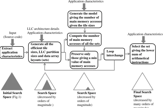
An abstract representation of the proposed methodology is illustrated in Fig. 2, while a detailed description (pseudocode) is depicted in Fig. 3. Going from left to right in Fig. 2, the first step includes a parsing phase in which all the characteristics of the loop kernels are extracted, i.e., data dependences, array references, subscript equations, loop iterators and bounds, and iterator nesting level values. Then, one mathematical equation is created for each array’s subscript, e.g., (A[2∗i+j]) and (B[i, j]) give (2∗i+
j =c1) and (i=c21andj =c22), respectively, where the following integer constants (c1, c21, c22) are found according to the corresponding loop bound values. Regarding 2-d arrays, two equations are built because the data array layout can be modified, e.g., in B[i, j]reference, ifN ∗i+j = c (where N is the number of the array columns) is considered instead of i =c1 andj =c2, then row-wise layout is enforced which may not be efficient.
Extract application characteristics
Generate all the efficient tile sizes, LLC partition sizes and data array layouts (sets)
Preserve only those giving a min value of main memory accesses
Loop interchange
Select the set giving the lower num of arithmetical instructions Input
(Source-code)
LLC architecture details Application characteristics
Initial Search Space (Fig.1)
Final Search Space (decreased by many orders of magnitude) Search Space
(decreased by orders of magnitude )
Search Space (decreased by orders of magnitude) Generate the model giving the number of main memory accesses given the tile sizes Application characteristics
Compute the number of main memory accesses of all the sets
Application characteristics
Fig. 2. Flow chart of the proposed methodology
Each subscript equation defines the memory access patterns of the specific array reference; data reuse is extracted by these equations.
Definition 3.1. Subscript equations which have more than one solution for at least one constant value, are named type2 equations. All others, are named type1 equations, e.g., (2∗i+j=c1) is a type2 equation, while (i=c21andj=c22) is a type1 equation.
[image:7.612.152.469.315.523.2]com-Parsing ();
Extract the application characteristics () ;
Transform all the array subscripts into math. equations ();
fori=1, num of all different iterators nesting level values (loop interchange) for j=1, num of loop kernels
Apply loop tiling to all the iterators ();
Subsect. 3.1 (); // Generate Subsect.3.1 inequalities Subsect. 3.2 (); // Generate Subsect.3.2 equations end j
Find candidate shared cache partition sizes (); for j=1, num of candidate shared cache partition sets for k=1, num of loop kernels
Produce all the tile sizes from the Subsect.3.1 inequalities ();
Compute the num of DDR accesses by using the Subsect.3.2 equations (); end k
Compute the overall num of DDR accesses - all the loop kernels (); Find the min value of DDR accesses
Store all the tile and cache partition sets giving a DDR value close to the min (); end j
end i
Subsect. 3.4 (); // Select the set giving the smallest num of arithmetical instructions
Fig. 3. The pseudocode of the proposed methodology
piler transformation is given which exploits data reuse of type2 equations. However, both type1 and type2 arrays may fetch their elements more than once in the case that the loop kernel contains at least one iterator that does not exist in the subscript equation, e.g., consider a loop kernel containing k, i, j iterators and B[i, j] reference; B[i, j]is accessed as many times askiterator indicates. Obviously, in our methodology type1 and type2 arrays are treated with different policies as they achieve data reuse in different ways.
After all the application characteristics have been extracted and all the subscript equations have been transformed into mathematical equations, one level of tiling is applied to all the loop kernels of all the tasks. Tiling is applied in order to partition the data arrays into smaller ones (tiles) which fit and remain in the cache during the execution; therefore, the data arrays are accessed less times from the slow and energy demanding main memory. Although we apply loop tiling to all the loop iterators in the first place, the output schedule/binary may contain tiling to only one or none of the iterators. The tile size selection procedure is analyzed in Subsection 3.1.
to those the proposed equations provide are discarded (they are inefficient), reducing the search space. We have implemented an automated C to C tool just for the studied algorithms, but a general tool can be implemented by using Rose [Lidman et al. 2012] for loop tiling and [Henretty et al. 2009] for data layout transformation.
Given that all the efficient tile and cache partition sizes have been extracted (Sub-section 3.1), we preserve only those giving a main memory access value close to the minimum, while all the others are discarded further decreasing the search space. The problem of finding the number of main memory accesses is theoretically formulated by exploiting the custom application characteristics (Subsection 3.2). In Subsection 3.2, one mathematical equation is generated for each loop kernel, giving the correspond-ing number of main memory accesses. The independent variables of this equation are the tile sizes; the tile sizes that minimize this equation achieve the minimum number of main memory accesses. For each candidate cache partition set, we generate all the efficient tile sizes (according to Subsection 3.1) and we compute the number of main memory accesses for each different tile size (the partition sizes that are bigger than the size of the biggest tiles possible, are not considered, decreasing the number of the candidate cache partition sets). We store and further process only the tile sizes giving a number of main memory accesses close to the minimum (5%), while the others are discarded (the previous threshold is empirically derived). The whole procedure is re-peated for all the loop kernels of all tasks. As noted, the pseudo code of our methodology is shown in Fig. 3.
The described procedure is repeated for all the different iterator nesting level values (loop interchange) as loop interchange impacts the generated equations. More specif-ically, when all the tile and cache partition sets providing a main memory accesses value close to the minimum have been derived, the procedure of Subsection 3.4 is applied in order to select (theoretically) the one offering the smallest number of arith-metic/addressing instructions. In other words, the configuration giving the minimum number of main memory accesses does not always give good performance due to the additional inserted arithmetic/addressing instructions required to support loop tiling that may degrade performance. To proceed with this, among all the tile sizes that give a main memory access value close to the minimum, we select those that offer the fewest number of the additional arithmetic instructions (this process is further analyzed in Subsection 3.4).
Although it is impractical to run all the different schedules (their number is huge) in order to prove that they give a large number of main memory accesses, a theoretical explanation can be given. First, the schedules that don’t belong to the aforementioned inequalities either use only a small portion of the cache or a larger, or they cannot remain in the cache. Second, for all the remaining schedules, we compute their main memory access values and we select only those giving a number close to the minimum. This problem is theoretically formulated in Subsection 3.2 and evaluated in Subsection 4.1 giving small error values. Third, from the best remaining binaries (in terms of main memory accesses), we select the one giving the less arithmetical instructions. This problem is theoretically formulated in Subsection 3.4 and evaluated in Subsection 4.3. The reminder of this section is divided into four subsections explaining in more de-tail the most complex steps of Fig. 2 and also giving a working example of the first two, most complex subsections.
3.1. Deriving efficient tile sizes, cache partition sizes, and data array layouts
[Nikolopoulos 2003]. However, as we show in this work, in order to apply loop tiling in an efficient way, the cache size and associativity and the data array layouts must be taken into account as they strongly depend on each other. The reason follows.
Let us give an example of a common matrix-matrix multiplication (MMM) algo-rithm. As noted by many reserachers [Whaley et al. 2001], the accumulated size of three rectangular tiles (one for each matrix) must be smaller or equal to the cache size; however, the elements of these tiles are not written in consecutive memory loca-tions e.g., the tile rows (matrix sub-rows) are not located in consecutive main memory locations, thus they do not use consecutive cache frames; this means that assuming a set-associative cache, they cannot simultaneously fit in the cache due to the cache modulo effect. Moreover, even if the tile elements are located in consecutive memory locations e.g., by enforcing a different data array layout, the three tiles cannot simul-taneously fit in the cache if it is two-way associative or direct mapped (although the elements of each array’s tile are going to be written in consecutive cache locations, the three tiles are not going to be written in consecutive cache locations, meaning that they are going to replace one another due to the cache modulo effect). Thus, it is ob-vious that the benefits of loop tiling can be maximized only when cache size, cache associativity and data array layouts, are addressed altogether in a single framework.
In order to find suitable tile and cache partition sizes, a shared cache inequality is produced for each loop kernel providing all the (near)-optimum tile and partition sizes; each inequality contains i) the tile size of each array and ii) the shape of each array tile. The tile and partition sizes and data array layouts that differ from the ones derived by the proposed methodology are automatically excluded decreasing the search space.
The inequality that provides all the efficient tile sizes and shapes for each loop kernel separately is formulated as:
m≤ d T ile1
LLCi/assoce+...+d
T ilen
LLCi/assoce ≤assoc (1)
whereLLCiis the LLC size / shared cache partition size used for loop kernel of taski; the number of different partitions equals to the number of the cores andLLCi =LLC1 for all the tasks mapped onto the first core.associs the LLC associativity e.g., for an 8-way associative cache,assoc = 8). m defines the lower bound of the tile sizes and it equals to the number of arrays in the loop kernel. In the special case where the number of the arrays is larger than the associativity value is not discussed in this paper (normally,(assoc≥8)).
T ileiis the tile size of the ith array and it is formulated as follows:
T ilei=T10×T20×Tn0 ×type×s (2) wheretypeis the size of each array’s element in bytes andTi0 equals to the tile size of the i iterator, e.g., in Fig. 4 (explained in subsequent section), the tile ofC[i][j]is T ileC =T1×T2×4(floating point elements; 4 bytes each).sis an integer and (s= 1
ors= 2);sdefines how many tiles of each array should be allocated in LLC according to the data reuse being achieved (it is explained below).
In order to satisfy that the tiles remain in the cache, the following four conditions must be met.
written onto a specific shared cache color, the tasks, virtual memory pages are mapped onto specific physical pages that corresponds onto specific page colors (thus into specific cache areas). The maximum number of partitions (colors) is given by LLC/(assoc×
page), where LLC, assoc and page are the LLC size, the LLC associativity, and the main memory page size, respectively. If the maximum number of colors is 32 in a 4-core system (p= 4), (LLC1 +LLC2 +LLC3 +LLC4 = 32) and (LLCi= (LLC/32)×d) whered= [1,32]and (i) is the core id.
Moreover, given that consecutive virtual addresses (array elements) are not mapped into consecutive physical addresses, we can further modify the OS page table mecha-nism (as above), in order the virtual main memory pages of each array to be assigned into consecutive physical pages and therefore shared cache locations (inside the ap-propriate cache partition). Under this scenario, the physical main memory pages of each array must contain consecutive color index values. Alternatively, the OS huge page tables can be used; in this case, the page size is many times larger and thus for reasonable array sizes, the array elements are written in consecutive physical memory locations.
Second, in order the tiles to remain in the cache during the whole execution, the tile elements that do not contain consecutive virtual main memory locations must be relocated (re-paged) in consecutive virtual main memory locations, known as tile-wise data array layout, i.e., all array elements are written in main memory in order; new arrays are created which replace the default ones. However, there are some special cases where the arrays do not contain consecutive memory locations but their layouts can remain unchanged. For example, this can happen when the tile size is very small (T ilei ≺(LLCi/assoc)/8) (this value has been found experimentally). In this case, the tile layout should not be changed and it is not inserted in Eq. 1.
Third, the array tiles directed to the same cache subregions do not conflict with each other; the number of cache lines with identical addresses needed for the array tiles is not larger than the (assoc) value, in order the tiles not to conflict with each other due to the cache modulo effect. This is achieved by choosing the correct tile sizes, tile shapes, and data array layouts. (d T ile1
LLCi/assoce) value in Eq. 1 is an integer that
represents the number ofLLCicache lines with identicalLLCaddresses used forT ile1.
(d T ile1
LLCi/assoce+...+d
T ilen
LLCi/assoce) value in Eq. 1 gives the number ofLLCi cache lines
with identical LLC addresses used for all the tiles; if this value becomes larger than the (assoc) value, the tiles cannot remain in the cache simultaneously. On the other hand, by using Eq. 1, an empty cache line is always granted for each different modulo (with respect to the size of the cache) of tile memory addresses. For the reminder of this paper we are going to say that (d T ile1
LLCi/assoce) cache ways are used for T ile1 (in
other words tiles are written in separate cache ways). A detailed example is given in Subsection 3.3. In the case that T ilei
LLCi/assoc would be used instead ofd
T ilei
LLCi/assoce, the
s= 2is selected; in this case, two consecutive tiles are allocated into LLC in order the second accessed tile not to displace another array’s tile.
Let us give an example of the fourth case above. Consider the second code of MMM in Fig. 4 assuming that the arrays are written tile-wise in main memory. The three tiles are accessed many times (data reuse) and thus they must remain in the cache. In the case that the three array tiles fit in the cache without any empty cache space left, when the second tile of A and B are loaded and multiplied by each other, some of their elements are going to be written on the tile of C; thus, some of the tile C elements will be loaded again. On the other hand, if we choose smaller tiles for A and B such that one tile of C and two consecutive tiles of A and B fit in the cache, the above problem will never occur and the number of cache misses will be minimized.
3.2. Deriving the model providing the number of main memory accesses with respect to the tile sizes
In this subsection the number of main memory accesses is derived theoretically by ex-ploiting the unique memory behavior of each loop kernel. More specifically, for each loop kernel one mathematical equation is created providing the corresponding num-ber of main memory accesses. The independent variables of this equation are the tile sizes. Normally, the larger the tile sizes are, the lower the number of the main mem-ory accesses is (assuming the tiles can remain in the cache). Obviously, larger cache partition sizes implies that larger the tile sizes can be used. However, the tile sizes are constrained by the shared cache architecture details, the designated cache partition size, and the number of the cores/tasks.
As mentioned in Subsection 3.1, all the tile elements contain only consecutive phys-ical main memory locations and the array tiles directed to the same cache subregions do not conflict with each other. Moreover, the tasks that run in parallel can access only their assigned shared cache space, thus different task tiles do not conflict with each other. Based on these observations, no unexpected misses occur and thus the number of main memory accesses can be calculated as follows.
The overall number of main memory accesses can be extracted by accumulating all the different loop kernel equations (Eq. 3). For the sake of simplicity, in the reminder of this paper we assume that each task contains only one loop kernel.
DDR−Acc.=
i=tasks
X
i=1
(T askiArrays+codei) (3)
wheretasksis the number of the tasks.T askiArraysandcodeirepresent the number of main memory accesses due to the threadidata arrays and source code, respectively (for data dominant applications (T askiArrays codei)). The main memory size al-located for the scalar variables is meaningless and it is ignored. It is important to mention that (codei) value is slightly affected by the loop tiling transformation and thus it is inserted in Eq. 3 as a constant value.
For the reminder of this paper, we assume that the underlying memory architecture consists of separate first level data and instruction caches (vast majority of architec-tures). In this case, the program code typically fits in L1 instruction cache; thus, it is assumed that the shared cache space is dominated by the data arrays of the loop kernels.
T askiArraysis given by the following equation
where T ype1array acc. and T ype2array acc. is the number of main memory ac-cesses of all type1 and type2 arrays, respectively (for task i). T ype1array acc. and T ype2array acc.are offered by Eq. 5 and Eq. 7, respectively.
T ype1 array acc.=
i=arrays1
X
i=1
(ArraySizei×ti+of f seti) (5)
where arrays1is the number of type1 arrays,ArraySizei is the size of arrayiand tirepresents how many timesarrayiis accessed from main memory.of f setigives the number of main memory data accesses that occur when the data array layout of array iis changed. Offset is either (of f seti = 2×ArraySizei) or (of f seti = 0) depending on whether the data layout of arrayiis changed or not; in the case that the layout of array iis changed, the array has to be loaded and then written again to main memory, thus it is (of f seti= 2×ArraySizei). However, when the array size is bigger or comparable to the cache size, then (of f seti2×ArraySizei). This is because the elements are always loaded in blocks (cache lines) and many blocks are loaded more than once (especially in the column-wise case). This is why we use a hand optimized code changing the layout in an efficient way, thus always achieving (of f seti= 2×ArraySizei).
tigives how many timesarrayiis accessed from main memory and is given by
ti=
j=N
Y
j=1
upj−lowj stepj ×
k=M
Y
k=1
upk−lowk
stepk (6)
whereN is the number of iterators exist above the upper new/tiling iterator of this array (tiling gives extra loops), M is the number of iterators exist between the new iterators of this array, if any.upj,lowj,stepj are the bound values of the corresponding new iterator, e.g., the Eq. 6 thej, kiterators ofA, B arrays in Fig. 4 are (none, jj) and (ii, none), respectively that correspond to (tA = TN2) and (tB = TN1), respectively. The first and the second products of Eq. 6 give how many times the array is accessed due to the iterators exist above the upper new iterator of this array and between the new iterators of this array, respectively, e.g., the B array in Fig. 4 does not containiiiterator and thus it is loaded (N/T1) times (the same holds for A array which is loaded (N/T2) times).
The number of main memory data accesses of type2 arrays is calculated as follows:
T ype2array acc.=Pi=arrays2
i=1 (ti×upstep1−low1 1×((up2−low2) +step1) +of f seti)
T ype2array acc.=ArraySize
(7)
where arrays2 is the number of type2 arrays, ti is calculated by Eq. 6, up1, low1, step1 are the bound values of the outermost type2 new/tiling iterator (e.g., ii iterator for in array in Fig. 4) and up2, low2 are the upper/lower bounds of the innermost type2 new/tiling iterator (e.g., jj iterator for in array in Fig. 4), e.g., (up1, low1, step1, up2, low2) values ofinarray in Fig. 4 are (N,0, T4, M,0); without any loss of generality we assume that the type2 equations contain only two iterators here. The first branch of eq. 7 holds when (((pattern size)−tile size)≥tile size); otherwise, the array is accessed only once and eq. 7 takes the value of the second branch. Keep in mind that (tile size) ofA[i+j]equals to (T1 +T2), where (T1, T2) are the tile sizes of (i, j), respectively.
times than type1 arrays because of the extra iterators they contain; when more than one iterator exists in a single subscript, e.g.,A[i+j+ 1], data patterns occur which they are repeated/accessed many times. For example, as the innermost iterator (let j) changes its value, the elements are accessed in a pattern, i.e.,A[3],A[4],A[5]etc, if i, j= [1, N]. When the outermost iterator (i) changes its value, this pattern is repeated, shifted by one position to the right (A[4],A[5],A[6]etc), reusing its elements. This holds for equations with more than 2 iterators too. Thus, the ((up2−low2) +step1) part in Eq. 7 gives the size of the pattern while (up1−low1
step1 ) offer how many times the pattern is
repeated/accessed.
//MMM
for (i=0;i!=N;i++) for (j=0;j!=N;j++)
for (k=0;k!=N;k++) C[i][j]+= A[i][k] * B[k][j];
//MMM – after loop tiling for (ii=0; ii!=N; ii+=T1)
for (jj=0; jj!=N; jj+=T2) for (kk=0; kk!=N; kk+=T3)
for (i=ii; i!=ii+T1; i++) for (j=jj; j!=jj+T2; j++)
for (k=kk; k!=kk+T3; k++) C[i][j]+= A[i][k] * B[k][j];
MMM - Main Memory accesses
C: 2 x N2
A: N3/T2
B: N3/T1
mmm_acc.= 2xN2 + N3/T2 + N3/T1 //FIR
for (i=0;i!=N;i++) for (j=0;j!=M;j++)
out[i] += in[ i + j ] * kernel[ j ];
//FIR – after loop tiling for (ii=0; ii!=N; ii+=T4)
for (jj=0; jj!=M; jj+=T5) for (i=ii; i!=ii+T4; i++)
for (j=jj; j!=jj+T5; j++) out[i] += in[ i + j ] * kernel[ j ];
FIR - Main Memory accesses
out: 2 x N in: N/T4 x (M+T4) kernel: M x N/T4
fir_acc.= 2xN + N/T4 x (M+T4) + M x N/T4 Equation giving the number of main memory accesses:
DDR-acc = Offset + mmm_acc. + fir_acc. + code (8)
Offset = 0 , if (T3=N & T2=N) (9) Offset = 2xN2 , if (T3≠N & T2=N) (10) Offset = 4xN2 , if (T3=N & T2≠N) (11)
Offset = 6xN2 , if (T3≠N & T2≠N) (12)
Equation giving all the efficient tile and LLC partition sizes for MMM
3 ≤ 𝑇1 𝑥 𝑇2 𝑥 𝑡𝑦𝑝𝑒𝐿𝐿𝐶1 𝑎𝑠𝑠𝑜𝑐 + 𝑇1 𝑥 𝑇3 𝑥 𝑡𝑦𝑝𝑒 𝑥 2𝐿𝐿𝐶1 𝑎𝑠𝑠𝑜𝑐 + 𝑇2 𝑥 𝑇3 𝑥 𝑡𝑦𝑝𝑒 𝑥 2𝐿𝐿𝐶1 𝑎𝑠𝑠𝑜𝑐 ≤ 𝑎𝑠𝑠𝑜𝑐 (13)
Equation giving all the efficient tile and LLC partition sizes for FIR
3 ≤ 𝐿𝐿𝐶2 𝑎𝑠𝑠𝑜𝑐𝑇4 𝑥 𝑡𝑦𝑝𝑒 + 𝑇4+𝑇5 𝑥 𝑡𝑦𝑝𝑒𝐿𝐿𝐶2 𝑎𝑠𝑠𝑜𝑐 + 𝐿𝐿𝐶2 𝑎𝑠𝑠𝑜𝑐𝑇5 𝑥 𝑡𝑦𝑝𝑒 ≤ 𝑎𝑠𝑠𝑜𝑐 (14)
LLC1+LLC2=LLC (15)
LLC1=LLC/d, d=[1,max_colors] (16) LLC2=LLC/d, d=[1,max_colors] (17) (0 < T1, T2, T3, T4 < N) & (0 < T5 < M) (18)
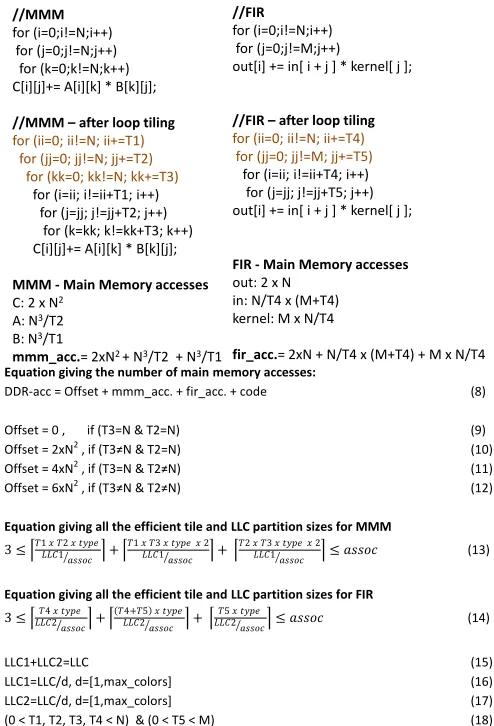
Fig. 4. Motivational example of Subsection 3.1 and Subsection 3.2
3.3. Working example of Subsection 3.1 and Subsection 3.2
[image:14.612.183.430.210.573.2]1stLLC partition
(MMM) 2ndLLC
partition (FIR) in
kernel
in in
in
1stLLC Partition
(MMM) 2ndLLC
Partition (FIR) in
kernel
kernel kernel
kernel C
A
A
A
C
A
C B B B
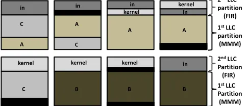
Fig. 5. An example on how data are stored in LLC regarding Fig. 4 (8-way LLC is assumed here). The blocks which are shown in black indicate ’empty’ cache lines.
loop kernels are: Matrix-Matrix Multiplication (MMM) and Finite Impulse Response (FIR).
According to the first step of the proposed methodology, loop tiling is applied to all the iterators giving extra loops and iterators. Then, one mathematical inequality for each loop kernel is derived providing all the efficient tile sizes and shapes, data array layouts, and cache partition sizes (Subsection 3.1). These are Eq.13 and Eq.14, for MMM and FIR, respectively. Eq.13 and Eq.14 satisfy that the tiles fit and remain in the cache. The two equations imply a large number of different implementations; moreover, if the tile elements contain no consecutive virtual main memory locations (x-axis is partitioned), the data array layout is appropriately modified. Eq.15-Eq.17 define that (LLC1, LLC2) are integers and that each task uses a subset of the max colors partitions; if more than two tasks exist, LLC1is used for all the tasks mapped onto the first core and LLC2 for the others. Finally, Eq.18 gives the range of tile sizes; it is important to note that if loop tiling has already been applied to the lower level memories, then extra equations are generated because the shared cache tiles must be multiples of the lower level cache tiles.
In Fig. 5, an example on how the arrays of Fig. 4 are stored in an 8-way LLC is shown. In order to satisfy that the tiles remain in the cache, four conditions must be met (Subsection 3.1). First, LLC is divided into 2 partitions (one for each core); in Fig. 5, LLC is partitioned horizontally and therefore both MMM and FIR use their private cache space. Second, all the tiles are written in consecutive LLC addresses, e.g., in Fig. 5 the C array is written in the 1st, 2nd and 5th LLC ways but in consec-utive addresses (the empty cache lines in the 5th way are due to the third condition explained hereafter). Third, the number of cache lines with identical addresses needed for the array tiles is not larger than the (assoc) value, so as the tiles not to conflict with each other due to the cache modulo effect, e.g., in Fig. 5, (c=dT1×T2×type
LLC1/assoce= 2),
(a = dT1LLC×T3×2×type
1/assoc e = 3) and (b = d
T2×T3×2×type
LLC1/assoc e = 3), where (c, a, b) represent the
number ofLLC1cache lines with identicalLLCaddresses used for (C, A, B) arrays; it
is like(C, A, B)arrays solely use (2,3,3) cache ways, respectively (although C array is written in three different cache ways, it is like using just two). Fourth, the next ac-cessed tiles do not conflict with the current ones (s= 2for A and B arrays), ensuring that the tiles remain in cache.
[image:15.612.190.431.97.201.2](2, N/T2, N/T1) times, respectively; C array is loaded and stored only once as its tiling iterators (ii, jj) have the smallest nesting level values (outermost ones), A array is accessed N/T2 times as jj iterator is located between its tiling/new iterators (ii, kk) and B array is accessedN/T1 times asii iterator is located upper from its iterators (jj, kk). Regarding FIR, (out, kernel) arrays are accessed (2, N/T2) times, respectively (out array is both loaded and stored); as far as theinarray is concerned, the (M +T4) pattern is repeated/loaded (N/T4) times and thus (N/T4×(M+T4)) accesses occur.
The equation giving the number of main memory accesses in total, is Eq.8. The source code size is a constant value (codevalue) and it is orders of magnitude smaller than themmm accandf ir accsize. Theof f setvalue takes four different values (Eq.9-Eq.12) because different tile shapes result in different data array layouts (regarding multi-dimensional arrays of MMM); given that the default data array layouts are row-wise, all the tiles that cut the x-axis do not contain consecutive main memory locations (and thus cache locations) and this is why their layout is changed, e.g., if (T36=N−1
andT2 =N−1) the data array layout of C array is changed, thus there is an offset of
2×N2main memory accesses (C array is both loaded and stored). The solution offering
the minimum number of main memory accesses is that obtaining the tile sizes that minimize Eq.8. However, the tile sizes and the cache partition sizes are constrained by Eq.13-Eq.18. If more than two tasks exist, Eq.8 changes accordingly.
3.4. Last touch: Deriving the solutions offering the fewest addressing instructions
Given that there are many different implementations achieving a main memory access value close to the minimum, we theoretically select the one giving the smallest number of arithmetic instructions by using a qualitative analysis; in this way the search space is further decreased.
Loop tiling affects the number of arithmetic/addressing instructions in two ways. First, according to Subsection 3.1, an extra loop kernel is added for each multidi-mensional array changing its layout; if the array tiles contain no consecutive virtual memory locations, the layout of the corresponding array is changed to tile-wise, i.e., all the elements are written in main memory in order (with the exact order they are fetched). Second, loop tiling adds extra loops to the loop kernel, increasing the over-all number of loop iterations and therefore the number of arithmetic instructions, as the corresponding loop body code is executed more times (more address computations occur - addressing instructions). Loop tiling is more expensive (in terms of arithmetic instructions) when it is applied to the innermost iterator and also when it is applied to more than one nested loops (a detailed analysis follows).
Obviously, the first reason is by far the one providing more arithmetic instructions than the second as extra loop kernels are introduced. Thus, we select the solution changing the layout of the minimum number of elements in total. The other solutions are discarded, further decreasing the search space. The total number of elements that change their memory layout is calculated for each case and the ones achieving the minimum number are preserved while all the others are discarded. Note that it is more efficient to change the layout of two small matrices than the layout of one big matrix.
af-fect the loop body code, a qualitative analysis on how loop tiling afaf-fects the number of arithmetic instructions follows (there are some special cases that the compiler slightly changes the loop code - a detailed discussion is given in the last paragraph).
Typically, each loop is transformed into 3 assembly instructions, i.e., 1 increment (e.g.,i=i+ 1), 1 compare (compare i to the N) and 1 jump instruction (ifi≺N jump back). Moreover, each loop is responsible of executing some code, depending on the target loop kernel. Thus, the more the loop iterations (in total), the more the arith-metic instructions. The number of loop iterations for a loop kernel is given by Eq. 19; Eq. 19 offers a qualitative measurement on the number of addressing instructions. The smaller the Eq. 19 value, the smaller the number of addressing instructions.
Loop iter.=Pi=loops
i=1 (
Qj=i
j=1
upj−lowj
stepj ) (19)
whereloopsis the number of the loops/iterators after loop tiling is applied (including the new iterators) and (up, low, step) are the corresponding iterator bound values.j= 1
corresponds to the outermost iterator (jis the iterator with the corresponding nesting level value). In Eq. 19,i= 1represents the number of loop iterations of the outermost loop-iterator,i = 2represents the number of loop iterations of the second outermost loop etc.
The outcome of Eq. 19 for 8 different MMM loop tiling implementations is given by Eq. 20-Eq. 27. Eq. 20 refers to the no tiling implementation, Eq. 21-Eq. 23 refers to one level of tiling, Eq. 24-Eq. 26 refers to two levels of tiling and Eq. 27 refers to the three levels of tiling implementation, e.g., in Eq. 20, the (i, j, k) iterators change their values (N, N2, N3) times, respectively. Eq. 21-Eq. 23 give only one extra iterator, Eq. 24-Eq. 26
give two extra iterators and Eq. 27 gives three. Eq. 19 gives a high number of loop iterations when loop tiling is applied to the innermost iterator (k) and also to more than one iterators. In the case that loop tiling is applied only to the innermost iterator (Eq. 23), the (kk, i, j, k) iterators change their values (N/T3, N2/T3, N3/T3, N3) times, while in the case that loop tiling is applied only to the outermost iterator (Eq. 21) the (ii, i, j, k) iterators change their values (N/T1, N, N2, N3) times and (N/T3 +N2/T3 +
N3/T3 +N3N/T1 +N+N2+N3).
Addrno=N3+N2+N (20)
Addri=N3+N2+N+N/T1 (21)
Addrj=N3+N2+N2/T2 +N/T2 (22)
Addrk=N3+N3/T3 +N2/T3 +N/T3 (23)
Addri−j=N3+N2+N2/T2 +N2/(T1×T2) +N/T1 (24)
Addri−k=N3+N3/T3 +N2/T3 +N2/(T1×T3) +N/T1 (25)
Addrj−k=N3+N3/T3 +N3/(T2×T3) +N2/(T2×T3) +N/T2 (26)
Addri−j−k=N3+N3/T3 +N3/(T2×T3) +N3/(T1×T2×T3) +N2/(T1×T2) +N/T1 (27)
As it can be observed by Eq. 20-Eq. 27, the increase in the number of arithmetic instructions is strongly affected by the number of the loops being tiled and by the innermost iterator tile size (N3/T3).
every case above, but to select the loop tiling parameters giving the minimum number of instructions. Thus, even if there is a special case that our analysis fails to give the desired loop tiling parameters, it will give other parameters with equally or slightly larger number of instructions. It is important to note that during our experimental analysis (Subsection 4), we did not face any such case.
4. EXPERIMENTAL RESULTS
The proposed methodology has been evaluated in terms of compilation time, main memory accesses, arithmetic instructions, performance and energy consumption. The experimental results of the proposed methodology are obtained using the well known gem5 [Binkert et al. 2011] and McPAT [Li et al. 2009] simulators. gem5 is con-figured to simulate a x86 multi-core architecture at 2Ghz with L2 shared cache. gem5 is used under system call emulation (SE) mode assuming in all cases an 8-issue out-of-order microarchitecture with the following instruction window parame-ters (ROB/IQ/LQ/SQ/Regs 192/64/32/32/256). The cache subsystem consists of a 32K, 64 byte block, 8-way, dual-ported, 2 cycle L1 data and instruction caches and a 16-way, 1MB L2, 20-cycle L2 cache. The characteristics of the simulated main memory are 8GB size, 60ns access time, and 12.8GB/s bandwidth. We extend the physically indexed L2 cache hashing/mapping policy in order to support the page colouring technique.
The bench-suite used in this study consists of eight well-known data dominant static kernels of linear algebra taken from PolyBench/C benchmark suite version 3.2 [Pouchet 2012]. These are: Matrix-Matrix Multiplication (MMM), Matrix-Vector Mul-tiplication (MVM), Gaussian Blur (Gauss.B) (5×5filter), Finite Impulse Response fil-ter (FIR), 2-d Seidel stencil computation (Seidel2d), a kernel containing mixed matrix vector multiplications (Gesumv), a kernel containing mixed upper triangular matrix matrix multiplications (Symm) and a multiresolution analysis kernel (Doitgen). The kernels are compiled using gcc4.8.4and icc17.0.4compiler with O3 optimization level. The gem5 simulation results are forwarded as input to McPAT; McPAT provides dy-namic and leakage power values of both processor and main memory in detail. The energy consumption is computed by (Etotal = (Pdynamic+Pleakage)∗Exec.time). The rest of section is divided into four parts; each one targeting to evaluate the proposed approach using a different evaluation metric.
4.1. Validating the approach described in Subsection3.2
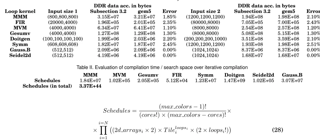
In this subsection, an evaluation of the accuracy of the number of main memory data accesses has been offered. For a more detailed analysis, two different input sizes are considered for each kernel. Table I illustrates the main memory data accesses calcu-lated by the equations of Subsection 3.2 and from gem5. The error values are also depicted. As we can observe, the error is small in both input sizes for all the kernels. Moreover, it is important to say that the simulator values are larger in all cases. Re-garding the Gaussian Blur and the Seidel2d kernels, the error is zero because the critical part of the arrays fits in the shared cache, thus the arrays are accessed only once from the main memory (no loop tiling is applied). We did not use larger input sizes for Gaussian Blur and Seidel2d kernels because in our opinion, they are not realistic.
4.2. Reduction of the search space
Table I. Evaluation of the accuracy of Subsection 3.2
DDR data acc. in bytes DDR data acc. in bytes
Loop kernel Input size 1 Subsection 3.2 gem5 Error Input size 2 Subsection 3.2 gem5 Error
MMM (800,800,800) 3.15E+07 3.21E+07 1.85% (1200,1200,1200) 1.94E+08 1.98E+08 2.10%
FIR (20000,4000) 1.96E+05 2.01E+05 2.35% (80000,8000) 7.05E+05 7.00E+05 2.43%
MVM (4000,4000) 6.34E+07 6.41E+07 1.10% (8000,8000) 2.54E+08 2.57E+08 1.20%
Gesumv (4000,4000) 1.27E+08 1.29E+08 1.30% (8000,8000) 5.08E+08 5.15E+08 1.30%
Doitgen (100,100,100,100) 1.99E+06 2.03E+06 2.20% (200,200,200,1000) 3.51E+08 3.59E+08 2.10%
Symm (608,608,608) 1.82E+07 1.87E+07 2.45% (1200,1200,1200) 1.93E+08 1.98E+08 2.51%
Gauss.B (512,512) 2.09E+06 2.09E+06 0.00% (1024,1024) 8.37E+06 8.37E+06 0.00%
Seidel2d (512,512) 4.19E+06 4.19E+06 0.00% (1024,1024) 1.68E+07 1.68E+07 0.00%
Table II. Evaluation of compilation time / search space over iterative compilation
MMM MVM Gesumv FIR Symm Doitgen Seidel2d Gauss.B
Schedules 1.84E+07 1.02E+05 2.05E+05 5.12E+04 1.23E+07 1.47E+09 1.02E+05 3.07E+07
Schedules (in total) 3.37E+44
Schedules= (max colors−1)!
(cores!)×(max colors−cores)!×
×
i=N
Y
i=1
(2d arraysi×2)×T ileloopsii ×(2×loopsi!)
(28)
where N is the number of the loop kernels,cores andmax colors are the number of the cores and cache colors, respectively. 2d arraysi is the number of multidimen-sional arrays in loop kerneliand indicates that each multidimensional array uses two different data layouts (the default and the tile-wise),T ilei is the number of different tile sizes for loop kernel iandloopsiis the number of the loops of kernel i. For a fair comparison, we use only (T ile= 20) different tile sizes for all the loop kernels.
The number of different cache partition sets among the cores is
((cores!)(×max colors(max colors−1)!−cores)!), while (2 × loopsi!) gives all different iterator nesting
level values (all different combinations of loop interchange). Finally, (T ileloopsii ) value gives all different tile sets. The overall number of binaries that Eq. 28 pro-duces is 3.37× 1044 (Table II) assuming cores = 8 and colors = 32. Given that
1sec = 3.17×10⁻⁸yearsand supposing that compilation time takes about 1 sec, the
compilation time will last for1037 years. On the contrary, instead of testing all those implementations, relying on the proposed methodology it is able to find the optimal solution in some minutes to some hours.
The number of different implementations for each loop kernel is also computed (Ta-ble II). The results in the first row of Ta(Ta-ble 2 are computed by (Qi=N
i=1 (2d arraysi ×
2)×T ileloopsi
i ×(2×loopsi!)
×colors), whereT ile= 20andcolor = 32. This equation gives all the different tile sizes, data array layouts, iterator nesting level values and colors that an implementation can use.
Regarding the compilation time of the proposed methodology, it is strongly affected by the k loop (Fig. 3) where all the candidate tile sizes are extracted in order to compute their DDR access values. So, the compilation time depends on the number of the can-didate tile sizes in total (all loop kernels). The compilation time in Subsection 4.4 lasts from 25 minutes to 2 hours, but a smaller/larger simulation time may occur depending on the above parameters.
tile sizes in total (all loop kernels). The compilation time in Subsection 4.4 lasts from 25 minutes (3rd set in Table III) to 2 hours (last 3 sets in Table III), but a smaller/larger simulation time may occur depending on the above parameters. Compilation times are measured in Linux-based PC machine using just the one core of Intel i7-6700 CPU running at 3.40GHz.
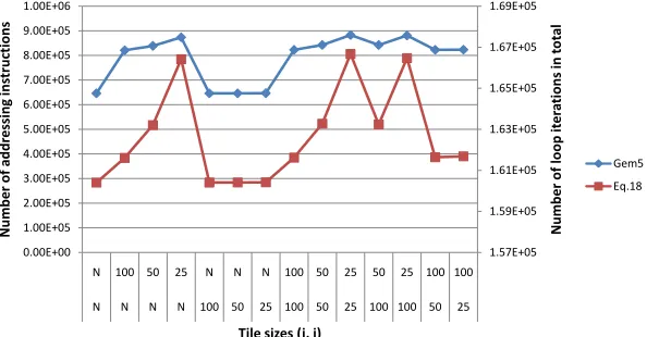
4.3. Validating the approach described in Subsection 3.4
2.10E+05 2.15E+05 2.20E+05 2.25E+05 2.30E+05 2.35E+05 2.40E+05 1.10E+06 1.15E+06 1.20E+06 1.25E+06 1.30E+06 1.35E+06 1.40E+06 1.45E+06 1.50E+06 1.55E+06 1.60E+06
N 30 20 10 N N N N N N 30 30 30 20 10 30 30 30 20 10 30 30 30 10
N N N N 30 20 10 N N N N N N N N 30 20 10 30 30 30 30 10 30
N N N N N N N 30 20 10 30 20 10 30 30 N N N N N 30 10 30 30
Nu m b er of loo p it e ra ti on s in t ot al Nu m b e r of a d d re ssi n g in str u ct ion s
Tile sizes (k, j, i)
Gem5 Eq.18
Fig. 6. Evaluation on the number of addressing instructions. Different tile sizes of MMM are shown (square matrices of size60×60)
1.57E+05 1.59E+05 1.61E+05 1.63E+05 1.65E+05 1.67E+05 1.69E+05 0.00E+00 1.00E+05 2.00E+05 3.00E+05 4.00E+05 5.00E+05 6.00E+05 7.00E+05 8.00E+05 9.00E+05 1.00E+06
N 100 50 25 N N N 100 50 25 50 25 100 100
N N N N 100 50 25 100 50 25 100 100 50 25
Nu m b e r of loo p it e ra ti on s in t ot al Nu m b e r of a d d re ssi n g in str u ct ion s
Tile sizes (j, i)
Gem5 Eq.18
Fig. 7. Evaluation on the number of addressing instructions. Different tile sizes of MVM (square matrix of size400×400)
In this subsection, an evaluation of the accuracy of the number of addressing in-structions is performed for MMM (Fig. 6) and MVM (Fig. 7). The results are similar for the other algorithms too.
[image:20.612.160.455.179.350.2] [image:20.612.160.457.401.556.2]number of addressing instructions measured by the gem5 simulator while the right y-axis indicates the Eq. 20-Eq. 27 values, generated by Eq. 19. As it can be deduced from Fig. 6, apart from the first point, Eq. 19 gives a qualitative measure of the number of addressing instructions. As we can see, the first point of the red line is higher than it was expected, because in this case the compiler applies more loop optimizations. As ex-pected, by applying tiling to more than one loop, the number of arithmetic instructions increases. Moreover, the number of arithmetic instructions is strongly affected by the tile size of the innermost iterator, i.e., (N3/T3) value. On the other hand, the fewest
number of arithmetic instructions occurs when no tiling is applied or when tiling is applied only to the outermost iterator (iiterator) and the second one when tiling is applied only to thejloop. The tile size affects the number of additional instructions to a small extent, except from the innermost one.
Regarding MVM loop kernel (Fig. 7), a square matrix of size (400×400) is selected. MVM contains two iterators, i.e., (i, j), where i is the outermost iterator. When loop tiling is applied only to the outermost iterator, the number of addressing instructions is close to the minimum (i.e., when no tiling is applied). On the other hand, when loop tiling is applied to the innermost one, the number of addressing instructions increases according to the tile size.
4.4. Evaluation in terms of main memory accesses, performance and energy consumption
In order to highlight the practical applicability of the proposed approach, we compare our method to a) gcc compiler, b) Intel icc compiler which applies automatic loop tiling, c) hand written loop tiling code, d) the proposed methodology without applying cache partitioning (Table III and Table IV).
In order to better understand the obtained results, a short analysis of each loop kernel is given. In general, the MMM, Symm and Doitgen loop kernels are the most data dominant kernels and this is why they achieve the highest DDR gain values. These three kernels a) use a large amount of data and b) their arrays are accessed not once but many times from the main memory (data reuse). Therefore, by providing more cache space to these kernels, the number of data accesses is reduced accordingly. On the other hand, Gaussian Blur and Seidel2d are the less data dominant loop kernels as the cache size of one shared cache color (here 32kb) is enough in order the arrays to be accessed only once from DDR (for matrix sizes up to (1024×1024). Thus, in this paper loop tiling is never applied to these kernels. Consider the MVM and Gesumv kernels, although they use a large amount of data, most of their data is fetched only once, thus providing more cache space to those kernels reduces the number of data accesses disproportionately, e.g., in MVM kernel (Y[i]+ =A[i][j]×X[j]), only Y and X vectors are accessed more than once (which are of small size) while the big matrix is loaded just once. Regarding FIR, although it uses a smaller amount of data, by providing more cache space, the number of data accesses is reduced accordingly.
As it was expected, a) icc performs better than gcc, b) hand written loop tiling code is more efficient than icc in most cases, c) using the proposed methodology without cache partitioning increases the cache pressure (and therefore the number of main memory accesses) but not in a high level (from1.004up to1.37more DDR accesses) as the sum of the tiles is smaller than the cache size and all the tiles contain consecutive main memory locations, d) the proposed methodology performs much better than loop tiling and icc.
Regarding the 1st set of loop kernels in Table III, Doitgen is the most data dominant kernel, thus it gets the maximum tile and cache size possible. MMM follows occupying 12 colours. Regarding MMM, automatic tiling perfoms very well. The other two kernels are of smaller size; two colours are enough in order to avoid loop tiling. Regarding the speedup values, the Doitgen kernel achieves the largest number of cpu cycles, thus the overall speedup is that of the Doitgen. The 1st set of loop kernels gives the smallest energy gain value as both the speedup and the DDR gain values are the smallest.
In the second set of kernels (Table III), Doitgen is the most data dominant kernel too, thus it gets the maximum tile and cache partition size possible. Symm and MMM follow. Regarding Gesumv, although it uses a large amount of data, providing more cache space to Gesumv, it reduces the number of data accesses disproportionately. This is why only 1 color has been assigned to this kernel.
In the third set of kernels (Table III), Symm is the most data dominant kernel, thus it gets the maximum tile and cache partition size possible. Symm achieves a lower number of data accesses than in the second set because it uses more cache colours and thus larger tile size. Regarding FIR, three cache colours are enough in order to avoid loop tiling and to minimize its number of data accesses. Regarding MVM and Gesumv, although they use a large amount of data, providing more cache space to these two kernels, reduces the number of data accesses disproportionately and this is why only one colour has been assigned to each kernel. The third set of loop kernels achieves by far the largest speedup and energy gain values; in this case, the thread with the maximum execution time amongst the four, is the Symm and not Doitgen. Although the DDR access gain is smaller than the second case, the energy gain is higher because of the lower execution time being achieved.
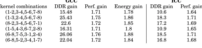
As far as the last 3 kernel combinations are concerned (eight loop kernels - Table III), the overall number of accesses is the smallest in the sixth set and the largest in the fourth. This means that the mapping of the sixth set is better in terms of main memory data accesses. The fourth set of kernels gives the largest number of accesses because the three most data dominant kernels (Doitgen, Symm, MMM) run on a different core, thus they compete each other for cache space. On the other hand, on the fifth and sixth sets, two of the three dominant kernels use the same core, thus only two kernels compete each other for cache space. Therefore, on the fourth and sixth sets, the three dominant kernels use a higher amount of cache size, reducing the overall number of accesses. Furthermore, considering the fourth set of loop kernels in Table III, the ker-nels that run first are more data dominant than the second ones. Thus, the second ones use more cache space than they need and as a consequence no tiling has been applied to them. The cache partition sizes are similar to those of the second set of Table III as the dominant kernels and also their input sizes are the same. As a consequence, the results are similar.
gain values and consequently the smallest speedup and energy gain values. This is be-cause in the first and fourth kernel combinations, the three most data dominant ker-nels (Doitgen, Symm, MMM) run on a different core and thus they compete each other for cache space. On the other hand, in the other combinations two of the three above kernels use the same core and thus only two kernels compete each other for cache space. It is important to say that the speedup values depend only on the kernel giving the maximum execution time (Doitgen). Thus, the speedup values and therefore the energy gain values would be much higher in the case that MMM or Symm achieve the maximum execution time and not Doigen, e.g., MMM/Symm use larger input values.
Table IV. Four cores and eight loop kernels, two to each core (3 different input sizes have been used)
GCC ICC
kernel combinations DDR gain Perf. gain Energy gain DDR gain Perf. gain
(1-2,3-4,5-6,7-8) 15.48 1.71 1.78 10.6 1.64
(1-3,2-4,5-6,7-8) 25.43 1.75 1.86 18.3 1.71
(8-2,3-4,5-6,7-1) 22.6 1.72 1.85 17.2 1.69
(1-5,4-3,6-7,2-8) 16.31 1.71 1.8 10.9 1.65
(6-8,7-5,3-1,2-4) 26.06 1.76 1.88 18.5 1.71
(6-8,5-2,3-4,1-7) 22.04 1.72 1.84 16.8 1.68
5. CONCLUSION
This paper presents and evaluates a memory management methodology of static data dominant applications in CMP shared caches. The proposed methodology combines software based cache partitioning, loop tiling, and data layout transformations in a single framework. We derive theoretical models that are able to control the cache space allocated to each task (leveraging the page coloring mechanism) and the loop tiling and data layout parameters at the same time.
ACKNOWLEDGMENTS
This work is supported by the collaborative project ”WCET-Aware Parallelization of Model-Based Applica-tions for Heterogeneous Parallel Systems (ARGO),” which is funded by the European Commission under Horizon 2020 Research and Innovation Action, Grant Agreement Number 688131.
REFERENCES
AGAKOV, F., BONILLA, E., CAVAZOS, J., FRANKE, B., FURSIN, G., O’BOYLE, M. F. P., THOMSON, J., TOU -SSAINT, M.,ANDWILLIAMS, C. K. I. 2006. Using Machine Learning to Focus Iterative Optimization.
InProceedings of the International Symposium on Code Generation and Optimization. CGO ’06. IEEE
Computer Society, Washington, DC, USA, 295–305.
ALMAGOR, L., COOPER, K. D., GROSUL, A., HARVEY, T. J., REEVES, S. W., SUBRAMANIAN, D., TORCZON, L.,ANDWATERMAN, T. 2004. Finding Effective Compilation Sequences.SIGPLAN Not. 39,7, 231–239. BANERJEE, U. 1993.Linear Equations and Inequalities. Springer US, Boston, MA, 49–94.
BAO, B.ANDDING, C. 2013. Defensive loop tiling for shared cache. InProceedings of the 2013 IEEE/ACM
International Symposium on Code Generation and Optimization (CGO). CGO ’13. IEEE Computer
So-ciety, Washington, DC, USA, 1–11.
BASKARAN, M. M., VYDYANATHAN, N., BONDHUGULA, U. K. R., RAMANUJAM, J., ROUNTEV, A.,AND SADAYAPPAN, P. 2009. Compiler-assisted dynamic scheduling for effective parallelization of loop nests
on multicore processors.SIGPLAN Not. 44,4, 219–228.
BINKERT, N., BECKMANN, B., BLACK, G., REINHARDT, S. K., SAIDI, A., BASU, A., HESTNESS, J., HOWER, D. R., KRISHNA, T., SARDASHTI, S., SEN, R., SEWELL, K., SHOAIB, M., VAISH, N., HILL, M. D.,AND
WOOD, D. A. 2011. The gem5 simulator.SIGARCH Comput. Archit. News 39,2, 1–7.