Using conceptual structures in enterprise architecture to
develop a new way of thinking and working for
organisations
POLOVINA, Simon <http://orcid.org/0000-0003-2961-6207> and VON
ROSING, Mark
Available from Sheffield Hallam University Research Archive (SHURA) at:
http://shura.shu.ac.uk/21101/
This document is the author deposited version. You are advised to consult the
publisher's version if you wish to cite from it.
Published version
POLOVINA, Simon and VON ROSING, Mark (2018). Using conceptual structures in
enterprise architecture to develop a new way of thinking and working for
organisations. In: CHAPMAN, Peter, ENDRES, Dominik and PERNELLE, Nathalie,
(eds.) Graph-based representation and reasoning : 23rd international conference on
conceptual structures, ICCS 2018, Edinburgh, UK, June 20-22, 2018, Proceedings.
Lecture Notes in Computer Science (10872). Springer, 176-190.
Copyright and re-use policy
See
http://shura.shu.ac.uk/information.html
Sheffield Hallam University Research Archive
Using Conceptual Structures in Enterprise
Architecture to develop a new Way of Thinking
and Working for Organisations
Simon Polovina1,2 and Mark von Rosing2
1 Conceptual Structures Research Group, Communication and Computing Research
Centre & Department of Computing, Sheffield Hallam University, Sheffield, UK
2 Global University Alliance, Chateau Du Grand Perray, La Bruere Sur Loir, France
[email protected], [email protected]
Abstract. Enterprise Architecture (EA) is a discipline that provides
generic patterns that any organisation can reuse throughout its own busi-ness, informatics and technical components. However, EA’s current way of thinking and working to achieve this aim is not standardised. EA thus continues to “reinvent the wheel” that causes mistakes or wastes resources on rediscovering what should already be known. We, therefore, represent the specific business, information and technology meta-models as patterns that can be fully reintegrated in one repeatable meta-model for the whole organisation. The outcome is a new agile way of think-ing and workthink-ing, highlighted by how EA works better in enterprise layers, sub-layers and levels of abstraction. To test the meta-models, two forms of Conceptual Structures known as Conceptual Graphs (CGs) and Formal Concept Analysis (FCA) are brought together through the CGtoFCA algorithm. The algorithm identifies how the layered meta-models can share meaning and truth and without having to recombine them into one large, unwieldy meta-model as the repeatable structure.
1
Introduction
Organisations can draw upon leading and best practices to gain insight into how best to fulfil their value and purpose. This insight ranges from understanding the external forces (e.g. the marketplace or non-profit environment) and internal forces (e.g. career ambitions of their employees) from which the organisations derive their strategy. The insight ranges to the operational behaviour (e.g. busi-ness processes), computer-based applications and data needed to implement that strategy most effectively.
Enterprise Architecture (EA) is a discipline that provides generic patterns that any organisation can reuse throughout its own business, informatics and data models in fulfilment of that organisation’s overall purpose. The organisation thus avoids “reinventing the wheel” which causes it to make mistakes or waste resources on rediscovering what is already known.
their specific needs. Computer science and informatics contributes to the ex-pressibility in these meta-models through its advances in ontology and seman-tics; together they capture the objects and relations that describe the interplay and effects of business in a formal, computable model [2, 3].
There are however multiple EA frameworks and methods, each with their own meta-models and associated approaches revealing a lack of mutual under-standing what the meta-models should consist of and how they ought to be used. The content within and interconnections between the meta-models for the ‘architectural domains’—i.e. business, information and technology—that make up the organisation are also interpreted differently according to the EA frame-work. The inconsistencies in the meta-models, and how to think and work with them undermine our conceptual understanding of organisations with potentially damaging effect. Consequently, organisations still end up reinventing the wheel. The classical way of thinking and working in EA’s architectural domains with a linear waterfall approach is counterproductive to the aims of EA. We evidence that representing the architectural domains as ‘layers’ enables us to think and work simultaneously within and across these multiple domains. We test this approach through Conceptual Structures, namely Conceptual Graphs and Formal Concept Analysis. As well as offering an agile way of thinking and working with EA, organisations can thus better draw upon the suggested best and leading practices to gain insight into how best to fulfil their value and purpose.
2
Understanding Architectural Layers in Organisations
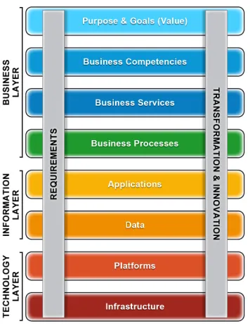
Independent of their size or industry, organisations share a common underlying structure that consists of the following enterprise layers identified from previous work [8]:
– Business: Such as the purpose and goal, competencies, processes, and services aspects;
– Information: Such as the application systems, as well as the data compo-nents;
– Technology: Such as the platform and infrastructure components.
These layers represent the three perspectives by which organisations are viewed. They are called layers because the business layer sits on top of the information layer that in turn sits on top of the technology layer. It epitomises that organisations are driven by their business needs that are enabled by their information systems (applications and data), which require the underlying tech-nology to run these systems.
Fig. 1. The Layers, and Sub-Layers The layers and sub-layers are an
[image:4.612.306.484.116.346.2]abstraction that represents and con-siders the enterprise as a whole [8]. For example, a policy, act, regula-tion or even a strategy is a part of the business layer, while the ap-plication systems and data aspects are a part of the information layer. It also highlights that organisational requirements cut across all the lay-ers, and organisational transforma-tion and innovatransforma-tion draws on the lay-ers too. The Layered Enterprise Ar-chitecture Development (LEAD) that Figure 1 depicts has been embodied by the industry practitioners’ enter-prise standards body LEADing Prac-tice (www.leadingpracPrac-tice.com) [7].
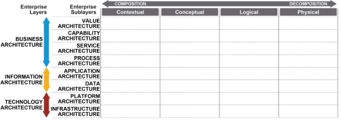
Figure 1 is further dimensioned by Figure 2, which explicates how the architectural domains (the lay-ers through their sub-laylay-ers) are fur-ther decomposed into architectural
views—i.e. contextual, conceptual, logical and physical. These views are called ‘levels’ and described shortly. The figure is now a matrix structure, where the layers and sub-layers are the rows, and the levels are the columns.
2.1 An Illustration
To illustrate Figure 2, Table 1 populates the layer and level structure3 with meta-model entities. These entities are accordingly referred to as ‘meta-objects’ which, for simplicity, we shall call objects.
The illustration (which supersedes previous work [4]) will be used to show how we can traverse through the layers and sub-layers, thinking and working si-multaneously within and between domains through the decomposition and com-position of the objects on all the levels. In so doing, we effortlessly integrate the right concept—i.e. object—across the different sub-layers when interlinking the EA for an organisation [8].
Returning to the table, ‘Application Function’ is an object under Application in the Information layer at level 2. Likewise, ‘Objective’ is a business layer Value object at level 3. The table lacks the technology layer but demonstrates the principle of layering, at least for the business and information layers. Also in line with Figure 2, Table 1’s level 1 is the contextual view, level 2 is the conceptual
3
Fig. 2.Layers with Levels (Contextual, Conceptual, Logical and Physical)
view, level 3 is the logical view, and level 4 is the physical view in architectural view terms.
Many of the objects can exist in the business, information and technology layers. These objects hence can both be repeated or related at more than one level (e.g. vision, mission, strategy, goal, business function, and business service), but are scoped according to their level of abstraction. For example, the strategy object at level 3 reflects an implementation of the strategy set by the highest-level and most abstract contextual depiction of the strategy object at highest-level 1 that in turn is mapped to level 3 through the intermediate conceptual strategy object at level 2. Level 4 is the physical form of the three levels above it. The table shows, for example, a performance indicator so that strategy and other value elements can be measured thereby to determine their effectiveness. Likewise, the most physical form of data sub-layer appears at level 4 (e.g. data table, key/foreign-key/attributes). The other level 4 objects for these and the other sub-layers (competency, service, process and application) can be viewed from the table. A more detailed discussion beyond illustrating the principle as we have described can be found elsewhere [7]. We will, however, explore the objects and their interrelationships as illustrated by Table 1 through Conceptual Structures.
3
Conceptual Structures
Conceptual Graphs (CGs) are a system of logic that express meaning in a form that is logically precise, humanly readable, and computationally tractable. CGs are a conceptual structure that serve as an intermediate language for translating between computer-oriented formalisms and natural languages. CGs graphical representation serve as a readable, but formal design and specification language [6]. CGs can thus powerfully represent the formal structure of meta-models while allowing them to be human-readable. A CG (Conceptual Graph) was therefore produced for each sub-layer in Table 1.
subjec-Table 1.The meta-model matrix with meta-objects (objects)
Layer&Sub-layer: Business Information
Value Competency Service Process Application Data
Level
1 Vision, Business Business Business Application Enterprise Mission Function Service Process Module Data Cluster
Strategy, Organizational Organizational
Goal unit unit
2 Vision, Business Business Process Application Department Mission Function Service Step Function Data Cluster
Strategy, Organizational Organizational
Goal unit unit
3 Vision, Business Business Process Application Workplace Mission Function Service Activity Task Data Entity
Strategy, Transaction
Goal Code,
System organizational
Unit
Dimension Objective Business Event Business
Object Object
Data Entity Data Entity Event
Business Data Data Media / Object Object
Accounts (Media)
Business Services Process Application Roles Roles Role Roles
Business Service Process Application Roles Rules Rules Rules
4 Performance Business Service Process IT Fact Table Indicator Compliance Level Performance Governance Customizing
Agreement Indicator Data Table (SLA) (PPI)
Master Data Table / View
Transaction Data Table
Revenue/ System Key
tive interpretation of the real-world phenomena for it to be captured in a logical structure. This procedure is akin to how the meta-models are produced in prac-tice, using for example Class Diagrams in UML, which CGs can help model [9]. A second form of conceptual structure known as Formal Concept Analysis (FCA) which is used in information science [5]. FCA provides an objective mathemat-ical interpretation of CGs’ logmathemat-ical but subjective human interpretations and is brought to bear through theCGtoFCAalgorithm [1]. A Formal Concept in FCA is the result of when certain conditions are met in a formal context:
– A formal context is a tripleK= (G,M,I), whereG is a set of objects,M
is a set of attributes, andI ⊆G×M is a binary (true/false) relation that expresses which objects have which attributes.
– (A,B) is a formal concept precisely when: • every object inAhas every attribute inB,
• for every object inG that is not inA, there is some attribute in B that the object does not have,
• for every attribute in M that is not inB, there is some object in A that does not have that attribute.
The Formal Concepts can then be presented in a lattice, namely a Formal Concept Lattice (FCL), as will be demonstrated shortly.
3.1 The Business Layer
The top layer, the Business Layer, establishes the connections of the enterprise to the environment through the identification of objects that describe the pur-pose and goal and therefore points both to the source of value and to concerns about the trade-offs necessary to optimise the ability to pursue this value. It further identifies the competencies needed to execute the functions, processes, and services within the environment. These are then used, in conjunction with business functions and other primitives, to organise and aid in the decomposition and organisation of the logical view and physical implementation of the busi-ness services and processes. In the following, we will elaborate on the individual sub-layers of the business layer.
Value The Value architecture sub-layer captures ideas about the vision, mission, strategy policy, act and regulations as well as all the purpose, goal and value that the organisation seeks to create.
Vision: v3V Goal: g3V assigned_to Strategy: s3V Strategy: s2V Vision: v2V consists_of consists_of measured_by assigned_to Goal: g2V assigned_to Mission: m2V Enterprise: @enterprise consists_of assigned_to consists_of Mission: m3V assigned_to assigned_to
Performance Indicator: o4V consists_of Objective: o3V assigned_to assigned_to assigned_to assigned_to consists_of consists_of assigned_to Goal: g1V Mission: m1V Strategy: s1V
Vision: v1V
[image:8.612.147.476.113.269.2]consists_of
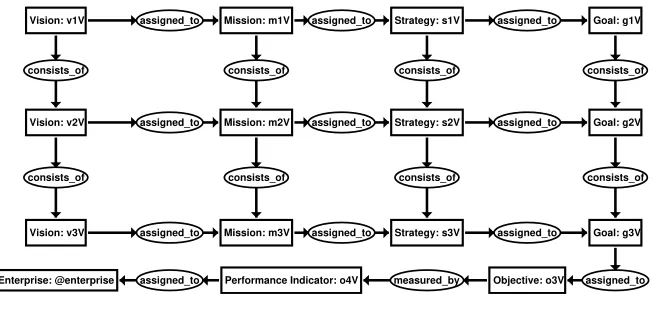
Fig. 3.Value, CGs
Level 3, Value and so on. The[Enterprise: @enterprise]concept follows an alternative pattern where@enterprise is a CGs’ measure referent [6].
The key significance of the[Enterprise: @enterprise]concept is that all the activities that make up an enterprise ultimately point to the enterprise, even though Enterprise is absent in Table 1. This follows EA’s holistic perspective. To draw from a building architect’s analogy, architecture ranges “From the blank piece of paper to the last nail in the wall.” EA follows the same principle, bringing all the objects at all the levels within a sub-layer to the same single point i.e.
[Enterprise: @enterprise] being the organisation (that in EA terms is the enterprise, which accounts for all kinds of organisations not just profit-making enterprises).
The relations (e.g.(assigned to)) describe the interrelationships between the objects in the table. Essentially the(assigned to)relation refers to a hor-izontal relation usually in the same sub-layer while(consists of)is a vertical relation between the levels in the layers. (There is no associated layer, sub-layer or level for Enterprise as it reflects the above-described culmination of all the sub-layers, and—as we shall see—all the levels). The relation(measured-by)
has its usual meaning.
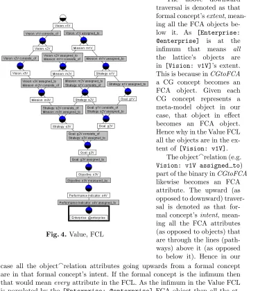
Figure 4 shows the FCL (Formal Concept Lattice) for the Value sub-layer. It is the result of the CGtoFCA algorithm transforming the object→ relation → object triples in the CG of Figure 3 to objectarelation→ object binaries4. An example binary is Vision:v1Vaassigned to→Mission: m1V. The neatly displayed lattice shows that [Enterprise: @enterprise] is bottommost i.e. at the infimum of the FCL, and highlighted by the bold rectangle in Figure 4. The topmost formal concept in a FCL is thesupremum. In this case the
supre-4
mum is represented by[Vision: v1V], which traverses downwards through the lines (pathways) connecting the intermediate concepts in the Value FCL case culminating in[Enterprise: @enterprise].
Fig. 4.Value, FCL
The above downward traversal is denoted as that formal concept’sextent, mean-ing all the FCA objects be-low it. As [Enterprise: @enterprise] is at the infimum that means all
the lattice’s objects are in [Vision: v1V]’s extent. This is because inCGtoFCA
a CG concept becomes an FCA object. Given each CG concept represents a meta-model object in our case, that object in effect becomes an FCA object. Hence why in the Value FCL all the objects are in the ex-tent of [Vision: v1V].
The objectarelation (e.g.
Vision: v1V assigned to) part of the binary inCGtoFCA
likewise becomes an FCA attribute. The upward (as opposed to downward) traver-sal is denoted as that for-mal concept’sintent, mean-ing all the FCA attributes (as opposed to objects) that are through the lines (path-ways) above it (as opposed to below it). Hence in our case all the objectarelation attributes going upwards from a formal concept are in that formal concept’s intent. If the formal concept is the infimum then that would meanevery attribute in the FCL. As the infimum in the Value FCL is populated by the [Enterprise: @enterprise] FCA object then all the at-tributes are in its intent includingVision: v1V assigned to.
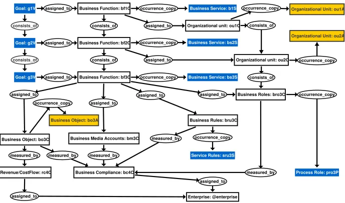
(e.g. The ‘..V’ in the referent for Goal shows it is in the Business Layer, un-der the Value sub-layer; the ‘..A’ in the referent for Business Object shows it is in the Information Layer, under the Application sub-layer). There is an
(occurrence copy) relation too. Essentially, this relation describes two con-cepts that are similar but are not co-referent (i.e. do not have the same refer-ent), which would make them the same. For example, [Business Function: bf1C] → (occurrence copy) → [Business Service: bs1S]. The rationale for such a relationship is further detailed elsewhere [4].
Business Object: bo3A
occurrence_copy assigned_to consists_of consists_of measured_by Enterprise: @enterprise assigned_to assigned_to occurrence_copy consists_of measured_by assigned_to assigned_to
Business Service: bs2S
Business Service: bs3S
measured_by measured_by assigned_to
Goal: g1V
Goal: g3V
Service Rules: sru3S
Process Role: pro3P Business Service: b1S
occurrence_copy Goal: g2V
occurrence_copy
Business Object: bo3C
Business Function: bf3C
occurrence_copy
occurrence_copy
Revenue/CostFlow: rc4C
Business Function: bf2C
assigned_to
Organizational unit: ou2C
measured_by
Organizational unit: ou1C
assigned_to Business Function: bf1C
consists_of
consists_of
Business Media Accounts: bm3C
occurrence_copy
assigned_to
Business Compliance: bc4C
occurrence_copy Organizational Unit: ou1A
Business Roles: bro3C
Business Rules: bru3C
consists_of
assigned_to
assigned_to
[image:10.612.137.481.235.438.2]Organizational Unit: ou2A
Fig. 5.Competency, CGs
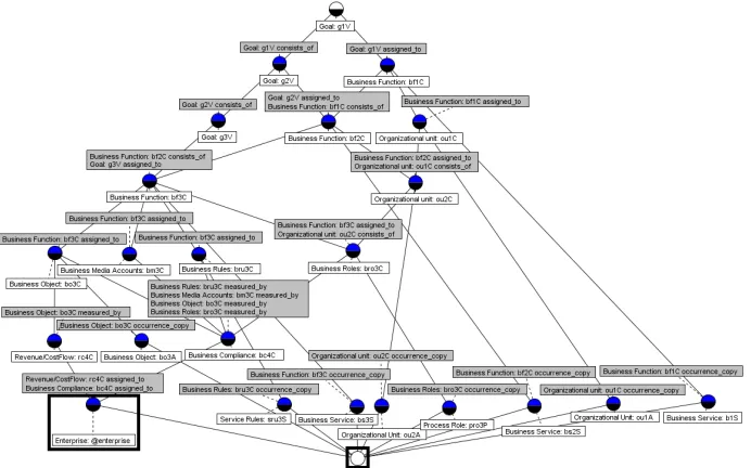
Again the same mapping throughCGtoFCA is applied and Figure 6 shows the resulting FCL. This time[Enterprise: @enterprise]is not bottommost, highlighted by the bold rectangles in Figure 6. The outcome is due to the con-cepts in the CG, such as[Business Service: b1S],[Service Rules: sru3S],
[Process Role: pro3P] that have their identical concept in another business sub-layer (e.g. S for Service, P for Process). These concepts do not have[Enterprise: @enterprise]in their extent for the Competency meta-model. Likewise[Business Object: bo3A], and[Organizational Unit: ou1A]in A the Application sub-layer do not end up at the CG concept[Enterprise: @enterprise]unlike the Value CG Figure 5 above. This again is because the[Enterprise: @enterprise]
is not in their extent.
Fig. 6.Competency, FCL
referent i.e. are co-referent [6]. For example the Value sub-layer concept[Goal: g1V] can join with its counterpart in Competency as they share ‘g1V’. This operation applies to all matching referents (co-referents) across all the sub-layers. If, when all the sub-layers are thus joined, all the paths lead to [Enterprise: @enterprise]then, together, the (Enterprise) Architectural principle of arriving at that ‘last nail in wall—i.e.[Enterprise: @enterprise]—is achieved.
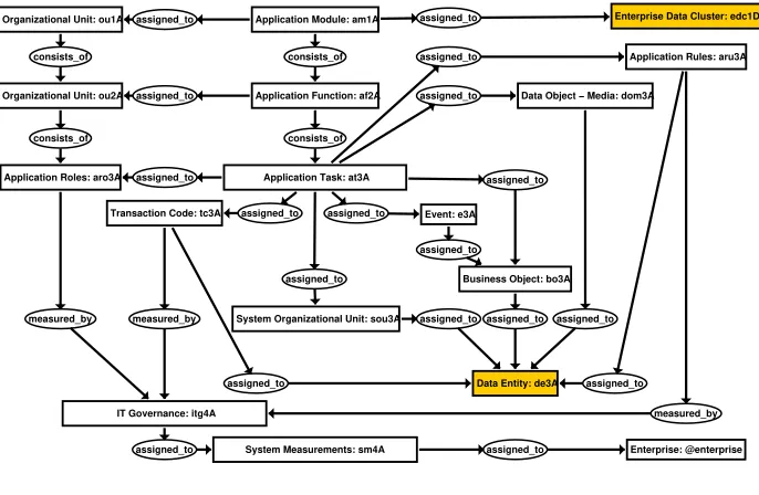
3.2 The Information Systems Layer
The Information Architecture Layer describes the objects, semantic relations and deliverables within the Application and Data sub-layers, and are the main components for both Application Architecture, Data Architecture and Informa-tion Architecture. The maps, matrices and models used within the ApplicaInforma-tion and Data sub-layers illustrate how their objects such as data goals, data flows, data services, data requirements and data components are linked to application goals, information flows, information services, application requirements, appli-cation flows and appliappli-cations components.
consists_of
measured_by assigned_to
assigned_to Transaction Code: tc3A
assigned_to
System Organizational Unit: sou3A measured_by
assigned_to Application Task: at3A
assigned_to Application Function: af2A
Organizational Unit: ou2A
assigned_to Organizational Unit: ou1A
assigned_to
Application Module: am1A
measured_by
assigned_to
Event: e3A assigned_to assigned_to
Data Object − Media: dom3A
assigned_to Business Object: bo3A assigned_to
Enterprise Data Cluster: edc1D
Application Rules: aru3A
IT Governance: itg4A
Data Entity: de3A Application Roles: aro3A
assigned_to consists_of
Enterprise: @enterprise System Measurements: sm4A
assigned_to assigned_to
consists_of
assigned_to consists_of
[image:12.612.136.479.276.500.2]assigned_to assigned_to
Fig. 7.Application, CGs
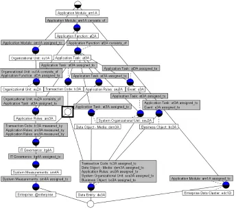
Application Due to space constraints the CG and FCL for the Service and
be the case in Figure 8. We can follow the intent and extent from and to the highlighted formal concept to get a sense of what name we might give this object, or confirm that it’s simply warranted thus doesn’t need its own object. Pertinent to us however is what appears at the infimum.
Fig. 8.Application, FCL
assigned_to consists_of
assigned_to
assigned_to
assigned_to
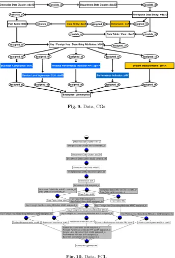
Key / Foreign Key / Describing Attributes: kfd4D
Enterprise: @enterprise
assigned_to assigned_to assigned_to
Fact Table: ft4D
Performance Indicator: pi4V
assigned_to Data Table / View: dtv4D
consists_of
Dimension: d3A assigned_to
Workplace Data Entity: wde3D
assigned_to Enterprise Data Cluster: edc1D Department Data Cluster: ddc2D
assigned_to Data Entity: de3A
Business Compliance: bc4C
consists_of
System Measurements: sm4A consists_of
Service Level Agreement SLA: sla4S
assigned_to
consists_of consists_of
Process Performance Indicator PPI : ppi4P
assigned_to assigned_to
[image:14.612.138.482.134.640.2]Fig. 9.Data, CGs
particular. The meta-models for each sub-layer make up the parts of the whole meta-model for the organisation.
4
The Whole Meta-model
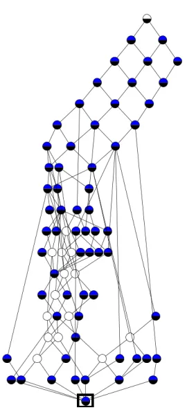
[image:15.612.348.483.223.519.2]Fig. 11.Combined FCL Figure 11 shows the FCL when each CG
meta-model for its architecture sub-layer (Value, Competency, Service, Process, Application and Data) are all combined through the co-referent links. Though not shown, it can be appreciated that even for our elementary illustration that would be one, huge, unwieldy CG.
Indeed the FCL Figure 11 that is generated from this CG looks complex, and the names of the FCA objects and attributes are omitted to avoid cluttering the lattice. (Also though not remarked on here, a number of formal concepts that appear in the middle do not have their own objects, denoted by the clear circles like the circle that appeared for Application.) What is evident nonetheless is that its infimum is a solid circle, highlighted by the bold rectangle in Figure 11. That is our single point of inter-est, thus obviating the need to visualise Fig-ure 11 at all. If its infimum object was shown it would be[Enterprise: @enterprise]. The layered meta-models thereby demonstrate that the organisation’s way of thinking and its way of working across all its layers through the sub-layers are aligned.
Even though the meta-model for each sub-layer apart from Value and Data did not have
[Enterprise: @enterprise] as its infimum, when combined into Figure 11 [Enterprise: @enterprise]became the infimum. It reminds
5
Conclusions
In EA, thinking and working in architecture domains alone is counterproductive. Through reconsidering the domains as architecture layers and sub-layers, and us-ing levels of contextual, conceptual, logical and physical abstraction within these sub-layers, we have been able to open up the objects’ multiple interaction points within and across the various layers, sub-layers and levels that better architect the organisation. From this agile approach, we can think and work with an EA in which the meta-models can repeatedly point to a single truth as opposed to the divergent meta-models that have characterised EA frameworks. Thereby, the or-ganisation is less likely to reinvent the wheel needlessly. We have portrayed how the layered EA can be enhanced by Formal Concepts. The use of CGs (Con-ceptual Graphs) and FCA (Formal Concept Analysis) through the CGtoFCA
algorithm provided a formal underpinning to the meta-models, pinpointing the direction of the interdependencies throughout the architecture layers, sub-layers and levels. Through the co-referent links it revealed how meta-models could be aligned towards that single truth and, along the way, without having to generate one large, unwieldy meta-model.
References
1. Simon Andrews and Simon Polovina.Exploring, Reasoning with and Validating Di-rected Graphs by Applying Formal Concept Analysis to Conceptual Graphs, volume LNAI 10775 of GKR 2017, Revised Selected Papers, pages 3–28. Springer, 2018. http://www.springer.com/gb/book/9783319781013.
2. The Open Group. 30. content metamodel, 2018. http://pubs.opengroup.org/architecture/togaf92-doc/arch/chap30.html.
3. Daniel Oberle. How ontologies benefit enterprise applications. Semantic Web Jour-nal, 5(6):473–491, 2014.
4. Simon Polovina, Hans-Jurgen Scheruhn, and von Rosing Mark. Modularising the Complex Meta-Models in Enterprise Systems Using Conceptual Structures, pages 261–283. Developments and Trends in Intelligent Technologies and Smart Systems. IGI Global, Hershey, PA, USA, 2018. ID: 189437.
5. Uta Priss. Formal concept analysis in information science.Annual Rev. Info. Sci & Technol., 40(1):521–543, December 2006.
6. John F. Sowa. Conceptual Graphs, pages 213–237. Handbook of Knowledge Rep-resentation, Foundations of Artificial Intelligence. Elsevier, Amsterdam, volume 3 edition, 2008.
7. Mark von Rosing. Using the business ontology to develop enterprise standards. International Journal of Conceptual Structures and Smart Applications (IJCSSA), 4(1):48–70, 2016. ID: 171391.
8. Mark von Rosing, Bonnie Urquhart, and John A. Zachman. Using a business on-tology for structuring artefacts: example - Northern Health. International Journal of Conceptual Structures and Smart Applications (IJCSSA), 3(1):42–85, 2015. ID: 142900.