Abstract—Nowadays among the steganography techniques
and particularly in conventional least significant bit (LSB) insertion method, there is a challenging issue and that is how to embed the secret bits in a medium like a typical 8-bit gray scale image in a way to be hidden to the human vision system. The gray scale image is called Cover Image and the pixels that carry the secret bits are called Target Pixels. The considerable point is how the capacity of every target pixel is achieved in order to maintain an acceptable imperceptibility of the secret data. The number of bits embedded in each target pixel is called Capacity. Some methods utilize either three or four adjacent neighbors of a target pixel so as to find its capacity such as BPCS, PVD and MBNS. In this paper, a method is proposed that uses at least four numbers of eight surrounding pixels of a target pixel. The more pixels are used for estimating the capacity, the higher image quality is achieved and vice versa. Thanks to this fact, smaller image’s distortion is made in the cover image. The method is called MSPU that stands for more surrounding pixels using.
Index Terms -Human vision system, image’s distortion, LSB
insertion method, more surrounding pixels.
INTRODUCTION
Nowadays information hiding and security is a challenging area. One of the branches in information hiding is steganography. Steganography is the art of hiding secret bits under the cover medium [1][2]. The simplest method in steganography is by embedding secret information in least significant bit(s) (LSB) of the cover medium. There are two main issues which should be considered when using the algorithm. The first issue is imperceptibility which is the visibility of the secret information to the human eyes. The second issue is capacity that is amount of secret information that can be hidden in the cover image [3].
Most of the new methods proposed in steganography consider human vision sensitivity as an essential factor [4] so that the very existence of the secret bits could not be detected by any third party. One of the methods to achieve this is by hiding the secret bits in the edges rather than the smooth areas of a cover image. A method which is called as Multiple Base Notational Systems (MBNS) considers the edge areas of a cover image. This method re-expresses the secret bits in multiple base notational systems [3]. Using this technique MBNS adds more security. Furthermore MBNS proposes a walk path through the cover image which is not a row by row selection of target pixels. MBNS method owns the best values in terms of performance and quality metrics in
Masoud Afrakhteh is with the Computer Science and Information Systems Department, Universiti Teknologi Malaysia, 81310 Malaysia (e-mail: masoudafrakhteh@gmail.com).
Subariah Ibrahim is with the Computer Science and Information Systems Department, Universiti Teknologi Malaysia, 81310 Malaysia (e-mail: Subariah@utm.my).
comparison with pixel value differencing (PVD) [6] and BPCS [3]. BPCS stands for bit-plane complexity segmentation method [5]. PVD replaces some certain blocks of the cover image with the secret data. This method embeds the amount of difference between every two corresponding blocks so that a larger amount of difference makes a greater modification and vice versa. Another method called optimal LSB method applies the same process of embedding which is used by simple LSB method but in the end, every target pixel value is supposed to be adjusted [7][8]. The adjustment process makes the best choice out of three candidates computed by either increasing or decreasing the modified value of a target pixel by a power of two. The best choice is the closest candidate value to the original value of the target pixel so that the error is decreased and the quality metric values go higher. To add more security, A-MELSBR method recommends the idea of considering a probability parameter in order to scatter the secret bits all over the cover image [9]. In this paper the main focus is to represent an improvement made in terms of imperceptibility in comparison with MBNS method. Also the same probability parameter as in [9] is applied in the proposed method. In addition, the proposed method utilizes more surrounding pixels in order to achieve the capacity of every target pixel.
The adjustment technique is discussed in Section II. The proposed algorithm is explained step by step in Section III. In Section IV, the experiment results are presented. Finally in Section V, the desired conclusion is made based on the results achieved.
ADJUSTMENT TECHNIQUE
As described earlier, once some secret bits are embedded in a target pixel, its value needs to be adjusted by a kind of process that its duty is to choose the closest gray-scale value to the original value of the target pixel so that the difference between the original and the new value of the target pixel becomes smaller. Smaller amount of difference makes the image’s distortion get smaller as well. In terms of imperceptibility, the value of a quality metric such as Peak Signal to Noise Ratio (PSNR) grows larger as this image’s distortion gets smaller. A higher PSNR value is regarded as an enhancement in imperceptibility. So the adjustment procedure can guarantee a reasonable image quality. The adjustment procedure is as follows:
1) If a target pixel value is changed by embedding secret bits, then it generates two other pixel values by flipping the K+1th bit of the pixel ʹ as follows:
( , ) = = + 2
= − 2
Steganography Using More Surrounding Pixels
where variable ʹis the modified value of a target pixel i which is called as andalready allowed to carry K number of secret bits in its first K least significant bits (K > 0). However in an 8-bit gray-scale image, there is a case that the value ʹ gets a number more than 255. On the other hand regarding ʹ value, there is a probability that the value becomes negative. To avoid this problem, in both cases it should be replaced with ʹ and no adjustment is needed.
2) " which is supposed to be replaced with ′ is achieved as follows:
"=
, | − | ≤ | − | ≤ | − |
, | − | ≤ | − | ≤ | − |
, | − | ≤ | − | ≤ | − |
(2)
STEGANOGRAPHIC SCHEME
The step by step embedding phase is as follows:
1) Suppose that a cover image consists of two areas such as secret area and embedding area. The former comprises of the top-most row and the left-most column of the cover image. The latter is the area in which secret bits will be embedded. It contains all the pixels other than the reserved pixels located in the secret area (Fig. 1). A secret key, SK is used to find the desired target pixels in a pseudo random way in the secret area.
2) Input SN as a seed number. It is used to make a pseudo random selection of the target pixels in the embedding area. Note that both SK and SN are the seed numbers generated by a pseudo random number generator (PRNG).
3) Let P, PL, M and N be the original image matrix, payload (in bits), and the number of rows and columns of the cover image respectively.
4) The experiments prove that if we use more than four bits out of a target pixel it can be seen by human vision system. Thus, assign number four to the variable Mb, which is the maximum number of bits allowed to be embedded with a specified amount of payload for each target pixel. The original value of a target pixel is represented by ( , ) and the modified value of the target pixel after embedding is called
(i, j).
5) The maximum capacity of the original cover image can be computed by the local variation formula as follows:
8 log 2 ∗ |σ({SPS })| , ∗
, (3)
where
σ
is the local variance value and SPS is the set of all surrounding pixels for a pixel.Reserved Reserved Reserved Reserved Reserved
Reserved 1 2
Reserved 3 4
[image:2.612.66.304.650.709.2]Reserved 5 6
Figure 1. An example of how target pixels are chosen in order (1,2, …, 6). The reserved pixels are located in the secret area and the rest of pixels are
6) The probability value and the desired pseudo random numbers is computed as below:
Probability = PL / Capacity; Rand(′twister′, seeed); RandMatrix = rand(a, b);
(4)
where the above equation is a simple PRNG and it is implemented using Mersenne Twister algorithm. This algorithm is the default built in PRNG method in MATLAB Versions 7.4 and later. Finally, RandMatrix is assigned by pseudo random numbers (0 < RandMatrix < 1).
7) The desired target pixels are chosen as follows:
( , ) ≤ ℎ
ℎ (5) The desired target pixels are chosen from the embedding area. The selection begins from the left-most pixel of the first row to the right-most pixel on the last row of the embedding area.
8) Determine a DynamicCapacity for a target pixel
( , ). DynamicCapacity means the number of bits that can be embedded in a target pixel. Pixels
( , + 1), ( + 1, − 1), ( + 1, ), ( + 1, + 1)
are considered as surrounding neighbors as long as they are not already chosen by PRNG, otherwise they are ignored. If they were chosen, it is expected that a wrong value would be computed for the capacity of the current target pixel. The reason is that the chosen surrounding pixels do not have the same values that they used to carry before their modification. However, there is no limitation for pixels such as
( , − 1), ( − 1, − 1), ( − 1, ) and ( − 1, + 1). All these pixels are considered as fixed neighbors, i.e. , they are always used for estimating the capacity of each target pixel (Fig. 2). Thus, the DynamicCapacity for a pixel can be calculated as follows:
( ∗| ({ } { })| , ) (6)
where CSP is the set of chosen target pixels located either after or beneath the target pixel. Total DynamicCapacity can be achieved by making a summation of every pixel’s DynamicCapacity. BestDelta is a regulation factor between zero and Mb. There is a probability that a pixel is chosen but it will not be used when the DynamicCapacity value equals to zero.
As described in the previous step, each pixel is supposed to carry a few bits of PL which is equal to its respective DynamicCapacity. The gray-scale result is called while original value is called Pi.
Always use Always use Always use
Always use Target pixel Use if not chosen
[image:3.612.72.299.46.102.2]Use if not chosen Use if not chosen Use if not chosen
Figure 2. Figure shows how to choose surrounding neighbors of a target pixel for estimating the maximum capacity (bits) that can be embedded in every target pixel.
9) Adjust the value of each target pixel using adjustment technique once embedment is finished in order to find the closest candidate to the original value of the target pixel. By doing this, the target pixel value will be replaced with the closest candidate.
10) If there are any secret bits left that are not embedded then decrease BestDelta and repeat step 8 - 9. Otherwise correct the Probability and go to step 7. These values are achieved by a simple divide and conquer searching algorithm. The range for BestDelta is between zero and Mb and for correcting the Probability just decrease the initial value from one to zero as much as possible as long as all message bits are embedded. It means that once the BestDelta value is achieved, the procedure is repeated until the smallest probability value embeds all the secret bits using the BestDelta found and scatters secret bits all over the cover image.
To explain further, suppose that the Probability is equal to one. Then the respective target pixels of the cover image will be chosen sequentially row by row as in (5). On the contrary, if the value of the initial probability is smaller than a target pixel random value provided that a full embedment of the secret bits is achieved, then the minimum probability should be chosen. In this case, secret bits are scattered as much as possible and the selection is no longer sequential.
11) Embed the secret parameters in the secret area. Once the desired values for BestDelta and probability are discovered, these secret parameters together with the rest of secret parameters such as SN, PL and Mb should be embedded in the secret area. The embedding process needs SK shared by both sender and receiver in order to scatter the secret data bits all over the secret area. Simple LSB insertion method is applied for embedding the secret parameters inside the secret area using one LSB of each target pixel. The modified cover-image is called as Stego Image. In order to recover message bits from the stego image, the receiver is expected to know SK so as to extract the rest of secret parameters. Knowing SK, the secret parameters embedded in the secret area of the stego-image can be extracted easily. The extraction procedure is as follows:
1) Generate random numbers using (4) and make the same comparison to find the desired target pixels of the medium as in (5).
2) Find the DynamicCapacity number of each target pixel as in (6). Using the number of bits embedded (DynamicCapacity), the message bits can be easily extracted from every pixel.
3) Knowing PL (to stop the procedure) the whole message is achieved by putting together all the message bits.
EXPERIMENTAL RESULTS
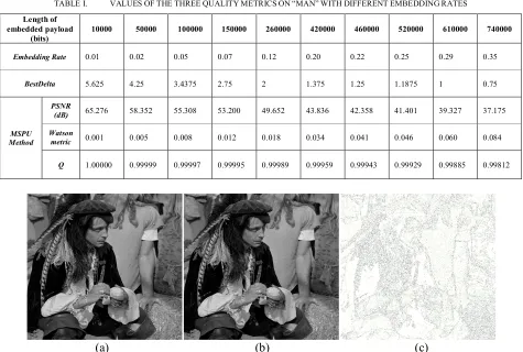
The algorithm is applied on image Man and it is tested for different payloads (Table I). The proposed method has better imperceptibility in smaller payloads and the security level is acceptable. In larger payloads its security level decreases but the algorithm still maintains the same metrics as in MBNS method as shown in Table II.
According to experimental results applied on three different images namely Lena, Man and Finstones, it can be concluded that for smaller payloads such as 420000 bits and below, the PSNR value gets better. This is due to the fact that more unselected immediate neighbors can be obtained and therefore the difference value decreases a great deal and higher PSNR metric is achieved (Fig. 4). The rest of metrics have not changed much. They are almost identical for the same payloads as compared to MBNS method. On the other hand, the difference in PSNR is clearer and that is merely due to utilizing more surrounding pixels for computing the capacity of each respective pixel.
There is a simple way to recognize which pixels carry more secret bits in comparison with other pixels. It is clear that each target pixel is modified in a few numbers of LSBs so that the gray scale values have a difference before and after embedding which is either zero or a bigger value. It is zero just at two cases. It happens whenever either source and destination bits are identical or no embedding is done at all. The more this value is, the more secret bits are concealed in the cover image. Since maximum number of bits allowed to be embedded equals to four in this algorithm, the biggest value that can be represented by four bits is 15 (2 − 1). The duty of an error image is to show the modification of pixels. An error image can be a kind of 8-bits gray scale image. In an 8-bit gray scale image 256 colors can be shown. To map all 16 colors to 256 colors, number 15 should be multiplied by 17. Finally the error image is achieved as follows:
= 255 − 17 × | ( , ) − ( , )|
As depicted in Fig. 3, the dark pixels represent the target pixels carrying the secret bits. The proposed algorithm embeds more in edge areas and so does MBNS method. Both algorithms mostly utilize the edge areas rather than smooth areas. As BestDelta value gets smaller so as to hide bigger payloads, both algorithms have to use a fraction of smooth areas as well; however the ratio of using smooth areas is less than the ratio of using edge areas.
CONCLUSION
Using this method, the imperceptibility in smaller payloads becomes higher than MBNS, PVD and BPCS methods. However the security is acceptable as long as the amount of payload is not more than embedding rate of 0.20 (420000 bits). This is due to using fixed number of neighbors (four) around each target pixel. In this case, the pseudo random walk path through the cover image is somehow sequentially row by row regardless of pixels located in smooth areas. In this regard perhaps the proposed method is no longer as secure as MBNS method. Therefore, if a method uses the same walk path applied in MBNS as well as the same idea which is proposed in this paper that is to use more than three neighbors, it would be secured enough even in higher payloads.
ACKNOWLEDGMENT
This work is supported by the Ministry of Science & Technology and Innovation (MOSTI), Malaysia and Research Management Center, Universiti Teknologi Malaysia under the VOT: 79309.
REFERENCES
[1] F. A. P. Petitcolas, R. J. Anderson and M. G. Kuhn, “Information hiding—A survey,” Proc. IEEE, vol. 87, pp. 1062–1078, 1999.
[2] H. Wang and S. Wang, “Cyber warfare—Steganography vs. Steganalysis,” Commun. ACM, vol. 47, no. 10, pp. 76–82, 2004.
[3] X. Zhang and S. Wang, “Steganography using multiple-base notational system and human vision sensitivity,” IEEE Signal Processing Letters, vol. 12, pp. 67–70, Jan. 2005.
[4] M. Kutter and S. Winkler, “A vision-based masking model for spread- spectrum image watermarking,” IEEE Trans. Image Processing, vol. 11,
[5] pp. 16–25, Jan. 2002.
[6] H. Noda, J. Spaulding, M. N. Shirazi, and E. Kawaguchi, “Application of bit-plane decomposition steganography to JPEG2000 encoded images,” IEEE Signal Processing Lett., vol. 9, no. 12, pp. 410–413, Dec. 2002.
[7] D.-C. Wu and W.-H. Tsai, “A steganographic method for images by pixel-value differencing,” Pattern Recognit. Lett., vol. 24, pp. 1613–1626, 2003.
[8] C. K. Chan and L. M. Cheng, “Hiding data in images by simple LSB substitution,” Pattern Recognition, pp. 469–474, Mar. 2004.
[9] N.I. Wu and M.S. Hwang,”Data Hiding: Current Status and Key Issues,” International Journal of Network Security, Vol.4, No.1, PP. 1–9, 2007.
[image:4.612.69.544.378.698.2][10] Y.K. Lee and L. h. Chen, “An Adaptive Image Steganographic Model Based on Minimum-Error LSB Replacement,” In Proceedings of the Ninth National Conference on Information Security. Taichung, Taiwan, 14-15, pp.8-15, 1999.
TABLE I. VALUESOFTHETHREEQUALITYMETRICSON“MAN”WITHDIFFERENTEMBEDDINGRATES
Length of embedded payload
(bits)
10000 50000 100000 150000 260000 420000 460000 520000 610000 740000
Embedding Rate 0.01 0.02 0.05 0.07 0.12 0.20 0.22 0.25 0.29 0.35
BestDelta 5.625 4.25 3.4375 2.75 2 1.375 1.25 1.1875 1 0.75
MSPU Method
PSNR
(dB) 65.276 58.352 55.308 53.200 49.652 43.836 42.358 41.401 39.327 37.175
Watson
metric 0.001 0.005 0.008 0.012 0.018 0.034 0.041 0.046 0.060 0.084
Q 1.00000 0.99999 0.99997 0.99995 0.99989 0.99959 0.99943 0.99929 0.99885 0.99812
TABLE II. VALUESOFTHETHREEQUALITYMETRICSAVERAGEDOVER3TESTIMAGESWITHDIFFERENTEMBEDDINGRATES
Length of embedded payload
(bits) 10000 50000 100000 150000 260000 420000 460000 520000 610000 740000
Embedding Rate 0.01 0.02 0.05 0.07 0.12 0.20 0.22 0.25 0.29 0.35
MSPU Method
PSNR (dB) 65.242 58.301 55.178 53.069 49.309 43.607 42.469 41.185 39.307 37.41
Watson metric 0.001 0.004 0.007 0.01 0.016 0.03 0.034 0.04 0.05 0.07
Q 1 0.99998 0.99996 0.99994 0.99986 0.99949 0.99939 0.99918 0.99876 0.99809
MBNS Method
PSNR (dB) 65.146 57.746 53.856 51.211 47.214 43.143 42.441 41.17 39.758 37.477
Watson metric 0.001 0.004 0.0076 0.011 0.018 0.031 0.034 0.04 0.048 0.067
[image:5.612.63.546.60.232.2]Q 1 0.99998 0.99995 0.99992 0.99981 0.99952 0.99944 0.99924 0.99893 0.99817
Figure 2. The performance of the new method in comparison with MBNS method for different payload (based on table I). 35
40 45 50 55 60 65
10000 50000 100000 150000 260000 420000 460000 520000 610000 740000
P
S
N
R
(
d
B
)
Payload (bits)