Abstract— This paper presents the design and the effectiveness
of reducing the unit cell size of microstrip reflectarray which is duplicated the same radiating aperture as quadratic backscatter. A reflectarrays with variable element sizes and reduced grid spacing have been designed at 10 GHz. For a given number of elements, it is shown that increased gain can be attainted for reduced unit cell size with no significant change in array size.
Index Terms— reflectarray, broad-beam antenna
I. INTRODUCTION
A planar reflector or microstrip reflectarray is a printed low-profile antenna that consists of a grounded flat onto which a quasi-periodic array of resonant conducting element (patches or dipoles) is etched [1]-[4]. This operation is similar in concept to a parabolic reflector that naturally forms a planar phase front when a feed is placed at its focus. Each element phase can be adjusted to produce a required phase law over the antenna aperture.
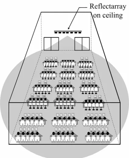
In the wireless communication applications such as wireless local area network (WLAN) large-scale indoor base station [5], it is desirable the antenna which has wide beam to cover a broad area. The wide beam reflectarray for WLAN antenna is an alternative as shown in Fig. 1 [6]. A reflectarray configuration is attractive because it allows a single mechanical design to be used repeatedly for a wide variety of different coverage specifications. The only changes are required that the printed reflecting element dimensions can be changed for each design, in order to generate the new shaped beam. Thus, many of the high recurring costs associated with shaped-reflector antennas can be eliminated with flat printed reflectarrays [7]. The flat geometry of a reflectarray also lends itself to easier placement and deployment on the WLAN large-scale indoor base station and also in terms of manufacture.
However, it is generally observed that when the antenna beam is enlarged, the antenna gain is reduced. In this paper, we have investigated the influence of the unit cell size of reflectarray on the gain performance. To achieve such
Manuscript received March 21, 2007. This work was supported in part by the Research Department, Institute of Engineering, Suranaree University of Technology, THAILAND.
P. K. and R. W are with the School of Telecommunication Engineering, Institute of Engineering, Suranaree University of Technology, Muang, Nakhon Ratchasima 30000, THAILAND. (corresponding author to provide phone: +66-44224392; fax: +66-44224603, e-mail: priam@ sut.ac.th).
[image:1.595.326.538.288.547.2]broad-beamwidth, phase of each array element in the reflectarray antenna is designed specifically to emulate the curvature of the backscatter function by using patches of different sizes. As the patch shape is not the aim of this work, it has been chosen to be simple to design regarding to the element position variation.
Figure 1. Reflectarray for WLAN large-scale indoor base station.
The first section, we will present the design approach as far as it concerns the unit cell size determination (Section II) and the reflection phase characteristic (Section III). In section IV, we apply this approach to calculate the radiation pattern of the proposed antenna. Finally, the conclusions are given in section V.
II. UNIT CELL SIZE DETERMINATION
Fig. 2 illustrates the geometry of an infinite reflectarray element. As indicated, s is the center-to-center elements spacing in both x and y directions that its size equal to unit cell size and L is the element size. To avoid the physical contacts
Design and Performance Improvement of
Broad-Beam Microstrip Reflectarray
among the adjacent elements, the unite cell size is must be larger than the element size L,
min unit cell size
{
}
=L. (1)(a)
[image:2.595.49.290.114.478.2](b)
Figure 2. Geometry of an infinite reflectarray element. The effective method for decreasing the unit cell size is to print the element on substrate, which reduces the size of reflectarray element. In microstrip antenna, many techniques have been reported to reduce the size of reflectarray element at a fixed operating frequency [8]. In general, reflectarray elements are half-wavelength structures at reflection phase 180° and operated at a resonant frequency, which is given by
0 ,
2 r
c f
L ε
≅ (2)
where c is the speed of light and
ε
r is the relative permittivity of the grounded microwave substrate. From (2), it is found that the physical unit cell size of reflectarray will be decreased at a fixed operating frequency due to the use of the microwave substrate with a larger permittivity.III. REFLECTION PHASE CHARACTERISTIC
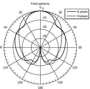
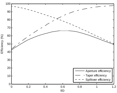
A. Backscatter Function for Broad-Beam Reflectarray In Fig. 2 (a), the perspective upper side view of the proposed antenna which is duplicated the same radiating aperture as quadratic backscatter fed by standard X-band horn. Fig. 3 shows the quadratic distribution of backscatter curvature by using the geometrical function as expressed in (3). Where D is assumed to be the diameter and A is the depth of the quadratic backscatter reflector, respectively. With a given feed horn as shown in Fig. 4, the appropriate distance between the horn and the center of reflectarray can be estimated by considering the spillover and taper efficiencies relations given in [9],[10]. At optimum value of aperture efficiency, a feed distance to diameter ratio (f/D) provides spillover and taper efficiencies of 76% and 84% respectively. Thus feed distance is chosen to be of 21.25 cm at
10
λ
reflector diameter. This structure radiates the beam that illuminates a predefined circular area without substantial spatial variation.( ) (1 (2 ) );2
2 2
D D
f z A z z
D
[image:2.595.336.525.324.462.2]′ = − ′ − ≤ ≤′ (3)
Figure 3. Quadratic distribution.
-45 -30 -15 0
60
120
30
150 0
180 30
150 60
120
90 90
Feed patterns
E-plane H-plane
[image:2.595.362.516.516.667.2]0 0.2 0.4 0.6 0.8 1 1.2 0
10 20 30 40 50 60 70 80 90 100
f/D
E
ff
ici
e
n
cy
(
%)
[image:3.595.66.264.91.249.2]Aperture efficiency Taper efficiency Spillover efficiency
Figure 5. Aperture efficiency of reflectarray.
[image:3.595.310.531.351.521.2]B. Required Phase Delay
Fig. 6 depicts the analysis model of broad-beam microstrip reflectarray [6], which parameters used in this figure are described below:
Figure 6. Analysis model of broad-beam microstrip reflectarray.
,
mn i
rG the vector from the feed to the mn-th reflectarray
element, which can be obtained by using flat geometry;
,
mn r
rG the reflected vector from the reflectarray surface to
far-field;
i
ρG the vector from the feed to the shaped reflector surface, which can be obtained by using curvature geometry;
r
ρG the reflected vector from the shaped reflector surface to far-field;
i
θ incidence angle;
r
θ reflection angle;
D diameter of the reflector;
f distance between the feed and the center of the
reflectarray.
In general, the feed may be positioned at distance from the reflectarray. The path lengths from the feed to all reflectarray elements are all different, which lead to different phase delays. The required phase, which is induced on the array, has to compensate for phase delay ∆Φmn between patch elements and
surface of quadratic backscatter as given by (4).
(
)
0 ,
360
in degree 1 ,
sin 2
b
mn i mn i
r
z f
N k ρ r
θ π
⎡ ⎛ − ⎞⎤
∆Φ =⎢ − ⎜ + − ⎟⎥
⎝ ⎠
⎣ ⎦
G G (4)
where ( ,x y zb b, b) describes the coordinate of the quadratic backscatter function and N is integer. From (4) indicates that the compensating phase can be repeated every 360 degree and the portion that is an integer multiple of 360 degree can be deleted.
-0.150 -0.1 -0.05 0 0.05 0.1 0.15
100 200 300 400 500 600 700
Patch position (m)
Requi
red
p
has
e del
ay
(
degr
ee)
0.8f0
1.0f0
[image:3.595.47.288.365.563.2]1.2f0
Figure 7. Calculated results of desired reflection phase properties.
The required phase delay that related to the patch position is determined for shaping beam of reflectarray as shown in Fig. 7 with various center frequencies (f0 = 10 GHz). These phases are duplicated the same radiating aperture as shape of quadratic backscatter. In the design, the cell elements are printed on a TACONIC substrate with thickness 0.762 mm and permittivity εr = 2.33. Because reduction of center-to-center element
spacing changes the elements position, the phase delays are decreased.
C. Element Characterization
8 8.5 9 9.5 10 10.5 11 11.5 12 0
50 100 150 200 250 300 350
Frequency (GHz)
Ref
lec
ti
on phas
e
(D
egr
ee)
L = 6 mm L = 7 mm L = 8 mm L = 9 mm L = 10 mm L = 11 mm
(a)
8 8.5 9 9.5 10 10.5 11 11.5 12
0 50 100 150 200 250 300 350
Frequency (GHz)
Ref
lec
ti
on phas
e (
D
egr
ee)
L = 4.0 mm L = 4.5 mm L = 5.0 mm L = 5.5 mm L = 6.0 mm L = 6.5 mm
(b)
6 7 8 9 10 11 12
0 50 100 150 200 250 300 350
Patch size (mm)
R
ef
lec
ti
on phas
e (
D
egr
ee)
s = 0.50 wavelength s = 0.55 wavelength s = 0.60 wavelength s = 0.65 wavelength
(c)
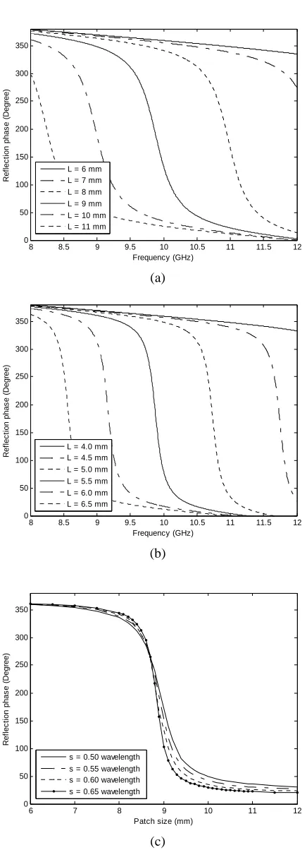
Figure 8. Simulated results of element characterization: (a) at εr = 2.33, s = 0.6λ0, (b) at εr = 6.15, s = 0.6λ0,
(c) at εr = 2.33, f0 = 10 GHz.
element design is not optimized, it will not scatter the signal from the feed effectively to form an efficient far-field beam. In this paper, the phase calibration technique is to use a full-wave method of moment and the infinite-array approach [6],[10] to model the effect of the finite grounded dielectric substrate underlying the single radiator.
Fig. 8 shows simulated results of reflection phase of infinite array. The obtained results indicated that, if the element size L is excessively small, either the reflection phase cannot be made to cover the full required 0° to 360° phase range, or it changes excessively fast around the element resonance. This available phase shift rang is limited by the reflectarray antenna bandwidth (around 4%). In Fig. 8(c), the reductions of unit cell size of reflectarray can reduce the slope of the phase response. For achieving reflectarray element with a reduced size at a fixed operating frequency, the use of a high-permittivity substrate is an effective method as shown in Fig. 8 (a)-(b).
IV. CALCULATION OF RADIATION PATTERN
With the compensating phases of all elements known, the far-field radiation patterns can be calculated by the conventional array theory [9], where the radiations of all elements are summed together as follows. Considering a planar array consisting of M×N elements that are nonuniformly illuminated by a low-gain feed, the reradiated field from the patches in an arbitrary direction, uˆ, will be of the form,
(
)
1 1
0
ˆ ˆ ˆ ˆ ˆ
( ) ( ) ( ) ( )
ˆ
exp ,
M N
mn z i r r
m n
mn i mn
E u F r a A r u A u u
jk r r u j
= =
= ⋅ ⋅ ⋅ ⋅ ⋅
⎡ ⎤
⋅ ⎣− + ⋅ − ∆Φ ⎦
∑∑
G GG G
(5)
where F is the feed pattern function, A is the reflectarray element pattern function, rGi is the vector from the centre of
reflectarray to mn-th element. uˆr is the reflected field pointing
[image:4.595.56.274.78.680.2]direction, and ∆Φmnis the required compensating phase of the mn-th element calculated by (4).
Table I
Characteristics of reflectarray. Unit cell size
(wavelength)
HPBW (degree)
Maximum Gain (dBi)
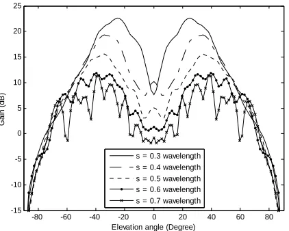
The radiated field from (5) provides the radiation characteristics, which are represented in Table I and Fig. 9 for various unit cell sizes. The prescribed field requirements have been satisfied by an appropriate choice of the radiating patches selected from the complex design curves obtained in the analysis stage. The steepness of the pattern edges and the angular positions of these edges confirm that the antenna efficiently illuminates the target area to be covered (±65°). Because of phase change versus element change, each unit cell size provides different characteristics such as -3 dB beam width (HPBW) and gain performance. The maximum gain is increased due to reduction of grid spacing. Thus, the HPBW is decreased and followed by the same order as the maximum gain. Fig. 10 shows maximum gain and gain at elevation angle 0° with various unit cell sizes.
-80 -60 -40 -20 0 20 40 60 80
-15 -10 -5 0 5 10 15 20 25
Elevation angle (Degree)
Ga
in
(
d
B
)
[image:5.595.71.277.513.682.2]s = 0.3 wavelength s = 0.4 wavelength s = 0.5 wavelength s = 0.6 wavelength s = 0.7 wavelength
Figure 9. Radiation pattern of quadratic function.
0.3 0.35 0.4 0.45 0.5 0.55 0.6 0.65
-5 0 5 10 15 20 25
Cell size (wavelength)
Ga
in
(
d
B
)
Maximum gain
Gain @ elevation angle = 0 degree
Figure 10. Gain versus unit cell size.
V. CONCLUSION
A broad-beam microstrip reflectarray designed from square patch has been presented. The prescribed field requirements have been satisfied by an appropriate choice of the radiating patches array selected from the complex design curves obtained in the analysis stage. Simulation of this reflectarray demonstrates that reduction of unit cell size can enhance bandwidth or reduce the slope of the reflection phase. In addition, the maximum gain is improved with small significant change in HPBW.
ACKNOWLEDGMENT
This work was supported by the Research Department Institute of Engineering, Suranaree University of Technology, Thailand.
REFERENCES
[1] R.E. Munson, H.A. Haddad, and J.W. Hanlen, “Microstrip reflectarray for
satellite communications and RCS enhancement or reduction,” U.S. patent 4 684 952, 1987.
[2] D.C. Chang and M.C. Huang, “Multiple-polarization microstrip
reflectarray antenna with high efficiency and low cross-polarization,” IEEE Trans. on Antenna and Propag., Vol.43, No.8, 1995, pp. 829-834.
[3] J.A. Encinar, “Design of two-layer printed reflectarrays using patches of
variable size,” IEEE Trans. on Antennas and Propag., Vol.49, 2001,
pp.1403-1410.
[4] D. G. Kurup, M. Himdi, and A. Rydberg, “Design of an unequally spaced
reflectarray,” IEEE Antennas and Wireless Propag. Letters, Vol.2, 2003,
pp.33-35.
[5] Peter F.M. Smulder, S. Khusial, and H.A.J. Herben, “A shaped reflector
antenna for 60-GHz indoor wireless LAN access points,” IEEE Trans. on
Verhicular Technology, Vol. 50, No. 2, 2001, pp. 584-591.
[6] P. Krachodnok and R. Wongsan, “Design of microstrip reflectarray
antenna using backscattering technique,” ITC-CSCC 2006 Conference
Proceedings, Thailand, Vol. 3, 2006, pp. 513-516.
[7] D.M. Pozar, S.D. Targonski, and R. Pokuls, “A shaped-beam microstrip
patch reflectarray,” IEEE Trans. on Antenna and Propag., Vol.47, Issue
7, 1999, pp. 1167-1173.
[8] Kin-Lu Wong, Compact and Broadband Microstrip Antenna, John Wiley
& Sons: New York, 2002, pp.22-86.
[9] J. Huang, Analysis of a microstrip reflectarray antenna for
microspacecraft applications, The Telecommunications and Data Acquisition Progress Report 42-120, 1995, pp. 153-173.
[10] D.M. Pozar, S.D. Targonski, and H.D. Syrigos “Design of millimeter
wave microstrip reflectarray,” IEEE Trans. on Antenna and Propagation,