PROVENANCE
MANAGEMENT
IN
PRACTICE
MATTHIJS OOMS
MASTER’S THESIS
Human Media Interaction Group Software Engineering Group Faculty of Electrical Engineering, Mathematics and Computer Science
GRADUATION COMMITTEE dr. P.E. van der Vet dr.ir. D. Hiemstra ir. I. Wassink dr.ir. R. Langerak September, 2009 Chairman HMI:
Chairman SE: 1 coordinator: 2 coordinator:
Summary
Scientific Workflow Managements Systems (SWfMSs), such as our own research prototype e-BioFlow, are being used by bioinformaticians to de-sign and run data-intensive experiments, connecting local and remote (Web) services and tools. Preserving data, for later inspection or reuse, determine the quality of results. To validate results is essential for sci-entific experiments. This can all be achieved by collecting provenance data. The dependencies between services and data are captured in a provenance model, such as the interchangeable Open Provenance Model (OPM).
This research consists of the following two provenance related goals:
1. Using a provenance archive effectively and efficiently as cache for workflow tasks.
2. Designing techniques to support browsing and navigation through a provenance archive.
Early in this research it was determined that a representative use case was needed. A use case, in the form of a scientific workflow, can show the performance improvements possibly gained by caching workflow tasks. If this use case is large-scale and data-intensive, and provenance is col-lected during its execution, it can also be used to show the levels of detail that can be addressed in the provenance data. Different levels of detail can be of aid whilst browsing and navigating provenance data.
iv | Summary
Many improvements were made to e-BioFlow in order to run OligoRAP, among which a new provenance implementation based on the OPM, en-abling provenance capturing during the execution of OligoRAP in e-Bio-Flow. During this research, e-BioFlow has grown from a proof-of-concept to a powerful research prototype.
For the OPM implementation, a profile for the OPM to collect prove-nance data during workflow execution has been proposed, that defines how provenance is collected during workflow enactment. The proposed profile maintains the hierarchical structure of (sub)workflows in the col-lected provenance data. With this profile, interoperability of the OPM for SWfMS is improved.
A caching strategy is proposed for caching workflow tasks and is imple-mented in e-BioFlow. It queries the OPM implementation for previous task executions. The queries are optimised by formulating them differ-ently and creating several indices. The performance improvement of each optimisation was measured using a query set taken from an Oli-goRAP cache run. Three tasks in OliOli-goRAP were cached, resulting in a performance improvement of 19%. A provenance archive based on the OPM can be used to effectively cache workflow tasks.
A provenance browser is introduced that incorporates several techniques to help browsing through large provenance archives. Its primary visual-isation is the graph representation specified by the OPM. The following techniques have been designed:
• An account navigator that uses the hierarchy captured by the
OPM-profile using composite tasks and subworkflows to visualise a tree structure of generic and detailed views towards the provenance data.
• The provenance browser can use several perspectives towards
prove-nance data, namely the data flow, control flow and resource per-spectives, identical to the perspectives used towards workflows in e-BioFlow. This enables the end-user to show detail on demand.
• A query panel that enables the end-user to specify a provenance
query. The result is directly visualised in the provenance browser, allowing the user to query for certain data items, tasks or even complete derivation trails.
• Retrieve tasks or data items that are not loaded in the provenance
| v
Preface
The work described in this thesis was carried out between March 2008 and September 2009 as the result of an extended final project combining the two Master of Science studies Human Media Interaction and Soft-ware Engineering at the University of Twente, Enschede.
During this period, many things have happened in my life, both good and bad. I happily remember the joyful days on which my nephew Yannick and niece Chiara were born, in contrast to the sad and somber days on which my mother and grandmother passed away. The day of my gradu-ation would have been one of the happiest in both their lives.
I would like to take this opportunity to thank my supervisors personally. You have contributed to many of the good times, and have been a great support in the bad.
Ingo, I hope you do not withdraw your supervision, as you said you would when you were demoted from chairman to coordinator due to university regulations. Regardless of your position in the committee, you have been an excellent supervisor. In the three years that we have worked together, I think we have formed a great team. Under the in-fluence of caffeine during our coffee breaks, many creative ideas were born leading to the improvement of e-BioFlow. I am proud to see how e-BioFlow has evolved, something neither of us had foreseen in the be-ginning. But at least equally important, I really enjoyed our pleasant non-work related discussions, over drinks at the NBIC conference for in-stance. Have you heard any fire alarms recently?
viii | Preface
in Maastricht and Lunteren, resulting in a poster- and oral presentation
of my work and attending the 3rd Provenance Challenge. Not to
for-get my nomination for the KNAW programme, during which I really en-joyed philosophising about the history of science and of which a publica-tion and visit to the BIOINFORMATICS 2010 Conference in Valencia will hopefully be the result.
Djoerd, although we have not seen each other as much as I have spo-ken Ingo and Paul, I would like to thank you for always expressing your honest and critical opinion towards my methods. Your feedback was es-sential for the research results described in this thesis.
Rom, I would like to thank you for your flexibility, for the useful tips and for the inspirational words you gave me the final days before my graduation.
During this research, I have had the privilege to be introduced to Pieter Neerincx, creator of OligoRAP. Pieter, without your quick, accurate and elaborate responses during many debug sessions, OligoRAP in e-BioFlow would still be future work.
This research and thesis benefited from conversations with friends and fellow lab-mates, Sander “4-uur Cup-a-Choco” Bockting, and Wim Bos, but most notably, Viet Yen Nguyen. Viet, since you are probably the smartest person I have ever met, it can be logically implied your feedback has improved this thesis. It is comforting to always see a green dot in front of your name, but also without it, I know you are there for me.
Finally, I wish to express my greatest thanks to my father, mother, my sister and her family, for their love and support.
Contents
SUMMARY iii
PREFACE vii
LIST OFFIGURES xiii
LIST OFTABLES xiv
LIST OFQUERIES ANDQUERYPLANS xv
1 INTRODUCTION 1
1.1 Provenance as Cache . . . 3
1.2 Provenance visualisation . . . 4
1.3 Outline of this thesis . . . 5
2 PROVENANCE INSCIENTIFICWORKFLOWS 9 2.1 Scientific Workflow Management Systems . . . 9
2.2 Provenance . . . 11
2.2.1 The Open Provenance Model . . . 13
2.2.2 Provenance archive as cache . . . 16
3 IMPROVEMENTS TO E-BIOFLOW 19 3.1 Motivation for the use of e-BioFlow . . . 19
3.2 Improvement implementation details . . . 20
3.3 Proof-of-principle case: OligoRAP . . . 23
3.3.1 Motivation . . . 24
3.3.2 Casting OligoRAP as a Workflow in e-BioFlow . . . 26
3.4 Provenance implementation . . . 27
3.4.1 Requirements for provenance implementations . . . 29
3.4.2 Database Design . . . 30
xii | Contents
3.6 Running OligoRAP: results . . . 37
3.7 Discussion . . . 40
4 USING PROVENANCE AS CACHE 45 4.1 Caching scheme . . . 45
4.1.1 Cache phase 1 . . . 46
4.1.2 Cache phase 2 . . . 47
4.2 Implementation . . . 48
4.2.1 Query for cache phase 1 . . . 49
4.2.2 Query used in cache phase 2 . . . 52
4.3 Optimising performance of phase 1 cache queries . . . 52
4.3.1 Query set and database used in measurements . . . 54
4.3.2 Optimising using subqueries . . . 54
4.3.3 Optimising using indices . . . 60
4.3.4 Performance of querying non-cached tasks . . . 62
4.3.5 Performance of Phase 2 queries . . . 63
4.4 Caching tasks in OligoRAP . . . 64
4.4.1 Results . . . 64
4.4.2 Discussion . . . 65
5 PROVENANCEVISUALISATION 69 5.1 Provenance Browser . . . 69
5.1.1 Navigating the Refinement Tree . . . 70
5.1.2 Perspectives . . . 72
5.1.3 Query interface . . . 78
5.1.4 Loading neighbours . . . 81
5.2 Browsing through an OligoRAP run . . . 82
5.3 Debugging with the Provenance Browser . . . 83
5.4 Discussion . . . 85
6 CONCLUSION 87 6.1 Summary . . . 87
6.2 Future Work . . . 90
APPENDICES
A QUERIES 95
B QUERY PLANS 99
List of Figures | xiii
List of Figures
2.1 OPM entities and causal dependencies. . . 14
3.1 Exotic MI workflow pattern . . . 28
3.2 Screenshot of OligoRAP in e-BioFlow . . . 29
3.3 ERD of Open Provenance Model . . . 31
3.4 Asynchronous BLAST workflow specification . . . 35
3.5 OPM graph of the execution of a BLAST job . . . 35
3.6 Matching pie chart results of OligoRAP . . . 39
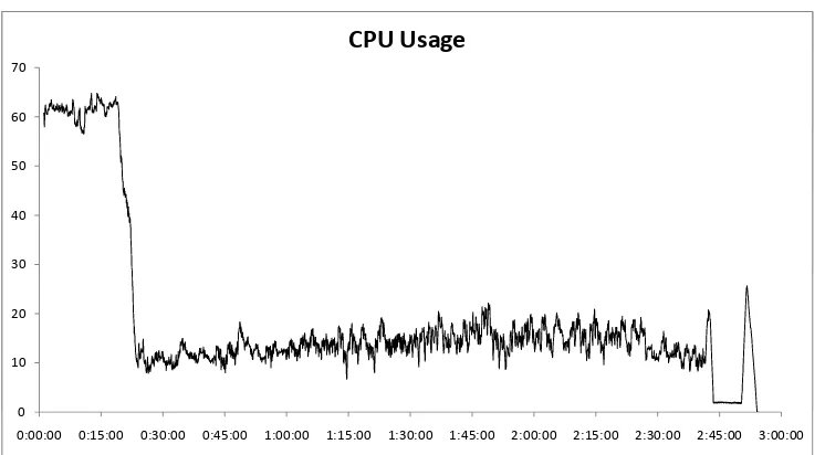
3.7 CPU load during OligoRAP run . . . 41
4.1 Provenance graph of a cache candidate . . . 47
5.1 Refinement tree structure . . . 72
5.2 Refinement tree with provenance elements . . . 73
5.3 Provenance perspectives. . . 74
(a) Data flow (b) Resource (c) Control flow 5.4 Screenshots of perspectives in e-BioFlow . . . 76
(a) Normal perspective (b) Data flow perspective (c) Resource perspective (d) Control flow perspective 5.5 Screenshots of pie charts in e-BioFlow . . . 80
(a) All pie charts
xiv | List of Tables
List of Tables
3.1 e-BioFlow improvements for running OligoRAP . . . 21
3.2 BioMOBY services used by OligoRAP . . . 25
3.3 OPM Database table specification . . . 32
3.4 The OPM-profile . . . 34
3.5 Storage sizes and durations of OligoRAP runs . . . 39
3.6 Provenance data statistics . . . 40
4.1 Query used in cache phase 1 . . . 48
4.2 View used for data comparison . . . 51
4.3 Query used in cache phase 2 . . . 52
4.4 Item value index sizes . . . 59
4.5 Form 2 and 3 and view 1 and 2 query statistics. . . 59
4.6 Created indices and their size . . . 61
4.7 Statistics of all indices. . . 62
4.8 Query performance of non-cached processes. . . 63
4.9 Query performance of phase 2 queries. . . 64
4.10 Durations of OligoRAP run with and without cache . . . 65
List of Queries and Query Plans | xv
List of Queries and Query Plans
4.1 Deriving query form 2 from query form 1 . . . 55
4.2 Deriving query form 3 from query form 2 . . . 57
5.1 Query for retrieving SVG pie charts . . . 79
5.2 Recursive query for retrieving a derivation trail . . . 81
A.1 Ineffective cache query (form 1) . . . 95
A.2 Cache query for MobyBlat in form 2 . . . 96
A.3 Cache query for MobyBlat in query form 3. . . 97
A.4 Cache query for Download url process . . . 97
B.1 Query plan for query A.1 . . . 100
B.2 Query plan for query A.2 . . . 102
B.3 Query plan for query A.3 . . . 104
B.4 Query plan for query A.3 with all effective indices . . . 106
B.5 Query plan for query A.4 . . . 108
B.6 Query plan for query A.4 with all effective indices . . . 109
B.7 Query plan for query A.3 . . . 110
B.8 Query plan for query A.4 with index i7 . . . 112
The greatest challenge to any thinker is stating the problem in a way that will allow a solution.
Bertrand Russell, 1872 - 1970
Chapter 1
Introduction
Whilst working for a long time on a single topic, this topic becomes so fa-miliar that it is surprising if others, even fellow computer scientists, have never even heard of it. The interest in the main topic of this research,
provenance, has grown in the last years and has become an established research field. Yet, the people working in this field still form a select group, therefore a proper introduction is in place.
Provenance means origin or derivation, and is also referred to as (data) lineage, audit trail or pedigree. Different techniques and provenance models have been proposed in many areas such as workflow systems and tools, visualisation, databases, digital libraries and knowledge represen-tation. In library systems for example, the structure of articles and their citations form an audit trail that helps the reader determine the quality of articles by its derivation from previous work. In database context prove-nance is used to capture the changes of data records. The importance of provenance can hardly be overestimated. It can be used to inspect and validate (intermediate) results of workflow runs and pay credit to the owners. Provenance makes results reproducible, which is a very impor-tant factor in scientific research.
In this research, provenance is used in the context of workflows, where provenance is primarily used to capture the execution of a workflow run. All intermediate results, timestamps, tasks and metadata of local and/or remote services are recorded by means of a certain provenance model. Workflow specifications are closely related to provenance models, they both define the relation between tasks and data. The difference is that a
workflow defines how tasks are going to be executed, whereas a
2 | Chapter 1- Introduction
Many workflow systems exist nowadays, such as Taverna, Kepler,
Chime-ra, Vistrails, Triana and our own research prototype e-BioFlow (see§2).
Some of these only focus on a certain domain. Taverna for instance provides tools mainly used by life scientists. Kepler is more generally addressed to as a Scientific Workflow Management System, a group of workflow systems to which e-BioFlow belongs as well. These workflow systems are named Scientific, because they are used for running scientific experiments. The workflows they run are scientific experiments them-selves, like an experiment performed by a life scientist in his lab. Diverg-ing from the wet-lab, some life scientists now run their experiments in a completely automated fashion. These are called in-silico experiments. A new scientist evolved, called the bioinformatician. Most bioinformati-cians have a stronger affiliation with biology than they have with infor-mation or computer science. They build software, and small tools, out
of need, simply because the tools do not exist. Workflow systems,
orig-inally used for business administration, form a useful means to model the tasks used in experiments, enabling re-execution of experiments and sharing them. Workflow editors or workbenches have been made more user friendly, so that not only the informatician, but also the life scientist can design and run workflows.
Among the major challenges faced today, that would benefit end-users, among which bioinformaticians, is how to integrate provenance tech-niques and models so that complete provenance can be derived for com-plex data products during workflow execution. Some of the workflows systems mentioned earlier capture provenance data, all using their own storage models. Another challenge is to make these different provenance aware systems interoperable. The Open Provenance Model (OPM) is one of the few existing proposals working towards this goal. Yet another issue is scalability. The amount of provenance data captured during workflow execution can be enormous, depending on the granularity, the level at which provenance is captured. Processing all the amounts of data in-volved in the experiments can take a long time, so efficiency is an
impor-tant factor. Davidson and Freire [11] have categorised these challenges
into four major open research problems:
1. Information management infrastructure and information overload 2. Interoperability
3. Analyse and visualise provenance data
1.1 Provenance as Cache | 3
This thesis is the result of a combined final project of two Master of Science studies, namely Human Media Interaction, and Software Engi-neering. It addresses all four challenges posed by Davidson and Freire, working towards two different research goals. Each study has its own re-search goal. The first goal, for Software Engineering (SE), is to improve the efficiency of workflow runs, by using a provenance archive as cache. The second goal, for Human Media Interaction (HMI), is to facilitate the interpretation of provenance data by means of a provenance browser that is able to navigate through a provenance archive. The studies share a common subgoal: collecting provenance data during workflow execu-tion. A large-scale data-intensive use case from the life science domain has been identified and casted as a workflow.
1.1
Provenance as Cache
During workflow execution, some tasks can be computationally inten-sive and thus time-consuming. The task, its input and its results can be stored in some archive, such as a provenance archive. If the output of such a task can be predicted based on its input, and a previous execution does exist in the archive, the output can be retrieved from the archive, by way of cache. By fetching the output directly from cache instead of re-executing the task itself can improve performance. This would be very beneficial in cases a workflow is executed repeatedly, or only a small number of parameters is changed. In an ‘ad-hoc’ workflow design ap-proach, when part of a workflow is executed, results inspected and new tasks added based on these results, it is desirable to not perform all previ-ous tasks over and over again, especially when they are time-consuming. Caching these tasks would be very helpful.
Besides performance gain, there are various other practical reasons for caching workflow tasks. If a workflow crashes, caching makes it possi-ble to resume execution. Webservices are frequently used in workflows. A drawback of webservices is that the server running them can be over-loaded, resulting in a slow performance and they can be unreachable due to network problems. If a task invoking a webservice is stored in cache, the workflow can still be executed.
4 | Chapter 1- Introduction
workflow tasks.
The large data volumes and different ways to store and query provenance archives make caching of workflows a challenging task. This challenge is one of the main motivations for this thesis and is expressed in the following research question:
SE Research Question Can a provenance archive be used ef-fectively and efficiently as cache for workflow tasks using the structure of the Open Provenance Model?
The result of this research is a new caching strategy (see Chapter 4), which is implemented in e-BioFlow. The proposed caching scheme de-fines how collected provenance data can be used as cache, without af-fecting the workflow itself. For this cache implementation several im-provements were necessary to e-BioFlow. Among the imim-provements is a direct implementation of the OPM to collect and store provenance data according to a newly defined OPM profile for workflow systems. The implementation of the OPM is tested with a large-scale data-intensive use case called OligoRAP, and the performance improvement that can be achieved by caching tasks in OligoRAP is measured. For a more elaborate
description of OligoRAP, see§3.3.
1.2
Provenance visualisation
A provenance archive can be always represented as a directed acyclic
graph, see §2.2.1. It is straightforward to use this representation when
visualising provenance data, the OPM is a clear example. During work-flow execution, many process, actor and data nodes are created, growing a huge provenance graph. Finding data in these large-scale graphs is a hard task: simply presenting the whole graph would not do the trick.
Groth [21] showed, with six use cases, that the average overhead of
col-lecting provenance data was about 13%. Of course this greatly depends on the type of use case that is used. In experiments performed with the Large Hadron Collider the amount of data that needs to be interpreted
is expected to be hundreds, even thousands of petabytes [13].
1.3 Outline of this thesis | 5
Having different levels of detail is useful when visualising data struc-tures by only representing data that matches users needs, enabling to zoom in and out to a certain level. The OPM provides some means to specify provenance data hierarchically, which can be of help when sur-veying, inspecting and navigating through a large provenance archive. The challenge to facilitate this way of navigation through large prove-nance archives is expressed in the following research question:
HMI Research QuestionCan level of detail be captured in the Open Provenance Model to support browsing and navigation through large provenance graphs?
The result of this research is a provenance browser that exploits the struc-ture of the OPM by deducing levels of detail. Additionally, several other techniques have been designed and implemented in the browser, such as support for different perspectives, a query interface, and an account nav-igator that enables a user to load only interesting parts of a provenance graph. The implementation is tested with and illustrated by the same use case OligoRAP.
1.3
Outline of this thesis
First, a literature study is presented in Chapter 2, providing a background of previous work in the field of provenance and workflow systems. Chap-ter 3 describes several improvements made to e-BioFlow, which were needed in order to run a large-scale data-intensive use case, called Oli-goRAP. OligoRAP is used as a proof-of-principle case for e-BioFlow. The provenance model identified for collecting and storing provenance data is the OPM, which is implemented in e-BioFlow. A generic mapping be-tween workflow events to OPM entities is made, to explicitly define what information is captured and how it is stored. This mapping is called a
profile for the OPM. The OPM-profile presented in§3.5 facilitates
6 | Chapter 1- Introduction
Provenance? No, it is not a region in France.
skeptico.blogs.com, July 2009
Chapter 2
Provenance in Scientific
Workflows
Workflow systems are being used extensively in the life science domain as well as in other scientific research areas. In this chapter an overview is presented of a selection of prominent scientific workflow systems, which appear to belong to the more popular workflow systems, based on their
occurrence in literature. In §2.2 several provenance implementations
are described, and more specifically the Open Provenance Model (see §2.2.1), which is the provenance model used throughout this research.
2.1
Scientific Workflow Management Systems
Many Scientific Workflow Management Systems (SWfMS) exist nowa-days, such as Taverna [34], Kepler [2], Triana [45], Vistrails [8],
Trident-[5] and our own research prototype e-BioFlow [52]. All these systems
have in common they are able to compose workflows using a graphical user interface also referred to as workflow editor or workbench. Fur-ther, they are able to execute these workflows, by mapping the workflow tasks to either local or remote (web) services. There is much overlap between the functionality of these systems, yet all of them approach sci-entific workflows from a slightly different angle.
Taverna [34; 35] is developed mainly for life scientists, and is the most
prominent workflow tool available in this area. At the current time of writing it provides a collection of over 3500 services, using a variety of
10 | Chapter 2- Provenance in Scientific Workflows
the latter two are webservice collections providing a uniform data format and ontology structure. Exact numbers are not mentioned consistently in literature and on the web, but these services are mainly tools for
bioinfor-maticians [12]. Still, Taverna has also been used to enact workflows in
other domains, like meteorology. The workflow editor has quite a learn-ing curve since the interface is not always that intuitive. It is announced that the user interface will be improved in future versions. Taverna work-flows provide means to iterate over lists, and provide nested processors to define workflows hierarchically.
Kepler [2] has been designed not specifically with the life scientist in
mind, but with scientists in general. It comes with some 350 services, called actors in Kepler. These are more general, such as R, Matlab, a generic WSDL actor and a database query actor. While other workflows systems are truly data oriented, like Taverna and Triana, Kepler was de-signed keeping in mind that workflows executed by scientists have a close resemblance to business process workflows. In addition to (and not in contrast with) business workflows, scientific workflows pose new chal-lenges, such as being computationally intensive and dealing with large
and complex derived data products [25]. Being general, life science
workflows still can be modelled in Kepler. In a recent combination, called
Kepler/pPOD [6] workflows are used for phylogenetic analysis, which
be-longs to the life science domain. In contrast with Taverna, where work-flows are directed acyclic graphs (DAGs), Kepler supports loops as well.
Triana [44] also intends to be a generic workflow system, employable
in different distributed and GRID environments. It is used in many do-mains, varying from gravitational wave analysis to galaxy visualisation
to fleet management and biodiversity problems [42]. An important key
aspect is its graphical user interface [12].
In Vistrails [8] too, as the name already suggests, the visualisation is an important factor. The focus lies on the visualisation of not only the work-flow but also its data. During the exploration process, scientists can gain insights by comparing multiple visualisations, which Vistrails tries to fa-cilitate. Another unique feature of Vistrails is how it deals with workflow modifications. Before the scientist is able to view and analyse final re-sults, the workflow probably has undergone numerous changes. These changes are all stored, since these are considered part of the scientific process.
Trident [5] is a scientific workflow workbench built on top of the
2.2 Provenance | 11
mainly applied and demonstrated in the field of oceanography 1. It
uses several technologies developed by Microsoft. Services can be pro-grammed in .NET, workflows can be connected to other software, such as Microsoft Word, and Silverlight is used to be able to run Trident on multiple platforms.
e-BioFlow [52] started as being only a workflow editor rather than
en-actor, able to compose workflows using three different perspectives, the control flow, data flow and resource perspective. In a multi-disciplinary environment, an intuitive workflow editor can improve the collaboration between scientists of different research areas. Having only a graphical
representation of workflows is not very useful, therefore the YAWL [47]
workflow engine was added. YAWL intends to be a complete workflow language, supporting all control-, data and resource workflow patterns
as specified by van der Aalst et al. [48]. Another advantage of YAWL is
its formal foundation, Petri nets, which enables validation of the work-flow. Evolving from these perspectives, new ways of designing workflows
are embraced, such as the recent ad-hoc workflow design [50]. During
development, usability has always been and still is a key factor.
2.2
Provenance
As was mentioned in the introduction, provenance means origin or
deriva-tion [21]. Some SWfMS, such as Taverna, Kepler and Trident, capture
provenance information during workflow execution, which is essential
to inspect (intermediate) result data [20] and validate experiment
re-sults [54]. Despite the high interest in provenance it is still an open
research area [9]. Many workshops have been held about the topic, such
as the International Provenance and Annotation Workshops of 2006 and 2008 [16;27].
Provenance data make experiments reproducible, simplify the discovery of changes in the underlying data and can be used to pay credit to the
owners of these data and resources [18]. In the life science domain as
in any other scientific research field, the trace fulfills a vital function
in the quality assurance of the scientific output [17]. SWfMS are ideal
environments to automatically capture provenance data. They ‘know’ which resources are accessed, when they are accessed and what data are
12 | Chapter 2- Provenance in Scientific Workflows
exchanged between the resources. Therefore, they can manage what is
called a process-oriented provenance model [40;55].
The idea of capturing provenance during in-silico experiments was
intro-duced by Stevens et al. [41]. They mention four different kinds of
prove-nance that can be collected: process, data, organisational and knowledge
level respectively. PASOA [29] for instance only captures provenance at
the process level. Kepler has workflow provenance support, but its focus is slightly shifted: it records the provenance of changes in the workflow specification made by the user himself, in other words, the evolution of a
workflow specification. This idea is also adopted in VisTrails [8]. Hence
Kepler and VisTrails capture provenance at the organisational level.
Ac-cording to Barga and Digiampietri [4] workflow systems lack support for
the collection of provenance at the data level, Stevens et al. [41] beg
to differ and present a counter example: myGRID. myGRID (the engine of
Taverna) captures provenance at all levels, using a combination of dif-ferent provenance systems, such as PASAO for the process level, and it uses its own data format to capture and store data at other levels. All the above mentioned SWfMSs use their own models for capturing and storing provenance data. Since all systems use their own data formats, interoperability is a big challenge.
Standardisation improves interoperability. One of the few existing ap-proaches to standardise on a provenance data model is the Minimal
In-formation About Microarray Experiments (MIAME) [7]. MIAME is
specif-ically designed to capture provenance data of microarray experiments. A SWfMS requires a more generic provenance model, since it is able to access a diversity of resources and is not limited to a single type of ex-periment, such as microarray experiments. The Open Provenance Model
specification [31] is one of the few existing proposals to capture
prove-nance in an interchangeable format, directly addressing the interoper-ability challenge. It is a generic model that intends to capture prove-nance data in a technology-agnostic manner. Despite all efforts, the OPM does not tackle the interoperability challenge completely yet. Identify-ing equivalent OPM features among workflow runs of different SWfMS
seems intuitive but is often a difficult task [9]. The main idea for the
Open Provenance Model was born at the 1stProvenance Challenge [30],
2.2 Provenance | 13
2.2.1
The Open Provenance Model
IPAW’06 brought forth the idea of the 1st Provenance Challenge [30],
which concluded with a workshop in Washington, DC (September, 2006). Existing provenance models were investigated and compared. When provenance data is used as a means for publication, it is important that
an interchangeable format is used. The 2nd Provenance Challenge
ad-dressed interoperability between provenance-aware systems and ended with a workshop held in California (June 2007), where an agreement was reached about a core provenance representation amongst the
thir-teen participating groups 2, called the Open Provenance Model,
abbre-viated OPM [28]. The 3rd Provenance Challenge ended with a
work-shop held in Amsterdam (June 2009), during which the OPM
specifica-tion [31] was evaluated, focussing on interoperability.
One of the goals of the 3rd Provenance Challenge was to stimulate the
development and use of concrete bindings and serialisations for the OPM.
Currently schemas for XML and RDF exist 3. A problem of serializing all
provenance data (including all data passed between tasks) in a single OPM XML file is that it can result in very large files and will end in
scalability problems [40]. How to include data in the value attributes of
an OPM XML serialization is undefined. This is still an interoperability
issue for hte OPM. Sahoo et al. [37] argue for a Semantic Web approach
to the OPM. They present a provenance algebra based on OWL, with a lot of similarity to the OPM (but without accounts).
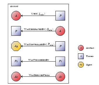
The OPM is a generic model, that represents the relation between pro-cesses (tasks), artifacts (data) and agents (actors, services). Every OPM is a directed acyclic graph (DAG), even when the underlying captured workflow contains loops. Therefore, OPM provenance data is also re-ferred to as an OPM graph. The nodes represent processes, artifacts
or agents. Edges represent causal dependencies, such as USED and WAS
-GENERATEDBY. Views on a particular OPM subgraph are called accounts.
An account can refine another, representing a more detailed view of the same execution.
DAGs are hard structures to represent: in a DAG two parents can have the same child, hence a DAG is not a tree. When serializing such data
2Provenance Challenges Wiki, http://twiki.ipaw.info/bin/view/Challenge,
last visited July 2009
3Open Provenance Model website,http://openprovenance.org/, last visited July
14 | Chapter 2- Provenance in Scientific Workflows
P
WasTriggeredBy
P2
A Used( )Irole
WasGeneratedBy( )Orole
P A
Ag WasControlledBy( )Prole P P1
A Artifact
P Process
Ag Agent
Account
[image:30.595.137.476.117.407.2]A1 A2 WasDerivedFrom
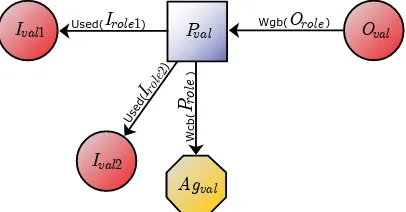
Figure 2.1: OPM entities and causal dependencies.
to XML for instance, cross links and references have to be made, the structure cannot be represented using the hierarchy of the XML directly. A relational database can be used to represent this structure.
OPM structure
Since the Open Provenance Model and its structure plays a major role throughout this thesis, the model is now explained in detail based on the OPM specification, version1.01. [31].
Entities and causal dependencies The OPM consists of three entity
types, Artifacts (data), Processes (tasks) and Agents (actors, services) respectively. In this thesis, entities are referred either as entities or ele-ments. Further, five causal dependency types are defined, also referred to as relations, namelyUSED,WASCONTROLLEDBY,WASGENERATEDBY,WASTRIG
-GEREDBY and WASDERIVEDFROM. See Figure 2.1 for a visual representation
of the entities and relations. Relations have a cause (its source) and an effect (its target).
2.2 Provenance | 15
states a certain processP has used a certain artifact A.
For theWASCONTROLLEDBYrelation, the cause is a Process and the effect an
Agent. It states a certain processP was controlled by a certain AgentAg.
For theWASGENERATEDBYrelation, the cause is an Artifact and the effect is
a Process. It states an artifact A was generated by a certain process P
(the artifact is the result, or output of the process).
For the WASTRIGGEREDBY relation, both cause and effect are processes. It
states that a processP1 was triggered by some other processP2.
For the WASDERIVEDFROM relation, the cause is an Artifact and the effect
is an Artifact. It states that artifact A1 was derived from A2. The OPM
specification defines that theWASDERIVEDFROMcan be derived from a
com-bination of a USED and WASGENERATEDBY between two artifactsA1,A2 and
a process P. If A1 is the input and A2 is the output of process P, then
A2 is derived from A1. During the 3rd Provenance Challenge, there was
a long discussion about this relation and whether or not this derivation always applies. None of the participants use the relation in their prove-nance implementations.
For the USED, WASGENERATEDBY and WASCONTROLLEDBY relations a Role is
defined. Roles capture additional information about a relation, in Figure 2.1, the roles Irole, Orole and Prole are used for these relations
respec-tively. Irole captures information about the context in which the artifact
was used. By a similar argument, Orole captures information about the
context in which the artifact was generated. Prole captures information
about the context in which an agent controlled a process.
Account views Relations and entities can belong to Accounts or Ac-count views. AcAc-counts are used to specify views towards the provenance data, at different levels of granularity for example. The granularity of a provenance graph, is determined during its recording stage. Suppose a computer performs some math calculation, say addition of two num-bers, and provenance data is collected. At a very fine-grained level, all CPU steps, memory addresses and values are recorded. At a very coarse-grained level, only the calculation itself is recorded as a single process, with the two input numbers and the result.
16 | Chapter 2- Provenance in Scientific Workflows
2.2.2
Provenance archive as cache
Besides using provenance in the traditional way, the provenance archive can also be used as cache, as described by Altintas et al. [1] as a proposal to be implemented in Kepler. They have called this idea smart re-runs. In their approach, parts of the workflow that remain unchanged (when for example a simple parameter is updated) in future executions, are re-placed by a StreamActor. This StreamActor fetches the necessary data from the provenance archive. This idea was the result of work previously done, collecting the provenance of the evolution of workflow specifica-tions. In the GRID domain, decentralised caching schemes have been
proposed where GRID jobs are represented as workflows [43].
Most caching schemes extend service invocation protocols directly, such
as the SOAP extension by Seltzsam et al. [38]. The Taverna Webservice
Data Proxy is developed to keep large data sets out of the Taverna
en-gine4. However, it can also be used to store intermediate results to serve
as a cache in order to speed up the re-execution of workflows. Caching
is also useful in case a workflow crashes. Wassink et al. [51] have
imple-mented a workflow to analyse large data sets related to microarray data. They have added additional tasks to support a restore and run option in case the workflow environment crashes. If a SWfMS can use its prove-nance archive as cache for workflow tasks then restore and run is directly supported.
4Taverna Webservice Data Proxy, last visited July 2009, http://www.cs.man.ac.
Models are to be used, not believed.
Henri Theil, 1924 - 2000
Chapter 3
Improvements to e-BioFlow
3.1
Motivation for the use of e-BioFlow
One of the main goals of this research and a requirement to reach both research goals is to collect provenance data during the execution of a large-scale data-intensive workflow. An excellent case study was found in the life science domain: OligoRAP. For a more elaborate description of
OligoRAP, see§3.3.
In order to collect provenance data for OligoRAP, which was originally written in Perl, OligoRAP had to be casted as a workflow, which requires a workflow system. Although Taverna is the most prominent tool for designing and running workflows in the life science domain, the work-flow tool chosen to implement OligoRAP is e-BioFlow. This choice was motivated by the following reasons. Neither e-BioFlow nor Taverna had provenance support at the time, so this had to be implemented in ei-ther workflow system. A great plus for e-BioFlow is its workflow engine
YAWL [47], that supports amongst others loops and conditional OR-split
and joins. It was anticipated that loops and conditions are needed for the polling of asynchronous webservices, which Taverna does not support. A plus for Taverna on the other hand is its support for BioMOBY
ser-vices [22], the protocol used in OligoRAP to invoke webservices, which
e-BioFlow did not support. A drawback of both systems is the use of main memory for storage of (intermediate) results, which was destined to become a problem for the large amounts of XML data generated by OligoRAP.
20 | Chapter 3- Improvements to e-BioFlow
OligoRAP and collect provenance data. Adding the support of loops to Taverna means changing its engine, which requires an extensive knowl-edge of its architecture. Features in Taverna 1 have been developed by many parties in parallel, which did not benefit the design of its architec-ture. A complete redesign was needed and is currently ongoing work for Taverna 2. e-BioFlow on the other hand has a clearly documented
archi-tecture [49]. In addition, the engine core does not need any adaptations
to support loops and conditions. A BioMOBY java framework already
ex-ists (JMoby1) that can be integrated in e-BioFlow with little effort. This
made e-BioFlow the primary choice.
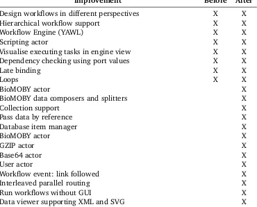
Some of the requirements needed to cast and run OligoRAP have been mentioned above, such as BioMOBY support and loops. A complete overview of the functionality needed to cast and run OligoRAP is listed in Table 3.1. The table indicates which functionality was already present in e-BioFlow, before and after casting OligoRAP as a workflow, presenting a clear overview of the implemented improvements.
First an overview is given of the minor implementation details, before continuing with the provenance implementation and details about Oli-goRAP.
3.2
Improvement implementation details
BioMOBY. JMoby is a Java BioMOBY framework supporting all features provided by BioMOBY registries, such as the invocation of Moby services and the construction of Moby data containers for the input and output of these services without the need to serialize XML. The ontology provided by a Moby service is used to create actors for each service available, amongst which the services needed by OligoRAP.
Moby services distinguish between primary and secondary inputs. Sec-ondary inputs are parameters. A bug was found in the JMoby implemen-tation: all secondary parameters are added with default values if not specified. This conflicts with some of the services used in OligoRAP: not all parameters in the BLAT service for instance can be combined. The bug was fixed in JMoby, only the specified secondary parameters are submit-ted.
1JMoby Project Website: http://BioMOBY.open-bio.org/CVS_CONTENT/
3.2 Improvement implementation details | 21
Improvement Before After
Design workflows in different perspectives X X
Hierarchical workflow support X X
Workflow Engine (YAWL) X X
Scripting actor X X
Visualise executing tasks in engine view X X
Dependency checking using port values X X
Late binding X X
Loops X X
BioMOBY actor X
BioMOBY data composers and splitters X
Collection support X
Pass data by reference X
Database item manager X
BioMOBY actor X
GZIP actor X
Base64 actor X
User actor X
Workflow event: link followed X
Interleaved parallel routing X
Run workflows without GUI X
[image:37.595.97.467.259.557.2]Data viewer supporting XML and SVG X
22 | Chapter 3- Improvements to e-BioFlow
Collection support. BioMOBY supports collections as input and output of services, which was required by the use case services as well. The Perl actor and BioMOBY actor were adapted to enable the correct use of collections.
Database item manager. The architecture of e-BioFlow provides an item manager that stores all items in memory. A reference of a data item is passed to the YAWL engine, instead of the complete data value. This approach made it possible to implement a database item manager, that stores the data values in a database and provides a database item refer-ence consisting of only an id with which the data value can be found.
The passing of data items as reference and storing values in the database partly solves the memory problem mentioned earlier: now only data items that are being processed (for example when checking data items or when passed to a service) are kept in memory. This approach no longer limits workflow execution to main memory size limits but raises the limit to disk storage space.
Actors. The OligoRAP client uses GZIP and Base64 encoding to transfer SVG images. These data transformations are implemented as two (lo-cal) actors in e-BioFlow, using the native GZIP and Base64 functionality provided by the Java API.
Another actor has been devised, mainly used for testing purposes: a User actor. This user actor shows an input screen consisting of all inputs the workflow task receives. The task outputs can be edited by the user, if the task has any. If the task only has inputs, it can be used to visualise data during workflow execution. Further, it can serve as a means for simple synchronisation: it waits for the user to continue.
Workflow event: link followed. When a workflow task is started, it is initiated by one or more previous tasks, unless it is the start task of the main workflow. YAWL throws events when a task starts and when a task finishes, but it is hard if not impossible to tell which process in-voked which other process, especially when many processes are running in parallel.
YAWL is based on Petri nets [46]. Using Petri net terminology, the link
3.3 Proof-of-principle case: OligoRAP | 23
new event is thrown in that case. Tasks are modelled as places in YAWL, thus the event can easily be translated to the workflow event of a link followed from task A to B.
Interleaved parallel routing. The workflow pattern ‘interleaved parallel
routing’ , pattern 17 as specified by van der Aalst [48], was required
for the use case. This pattern states that the order in which a set of tasks is executed is of no importance, but none of the tasks in the set are allowed to be executed at the same time. YAWL does not directly support this pattern, but it can be implemented in e-BioFlow without changing the YAWL engine, by allowing only a maximum number of instances per actor. If this maximum number of instances is set to one, none of the tasks performed by the actor are executed at the same time.
Data viewer. A data viewer component has been implemented that is
able to visualise data items in e-BioFlow. Currently supported visualisa-tions are normal string, XML data and SVG, JPG and PNG images. The viewer can easily be extended to support more. This component is used in the user actor.
3.3
Proof-of-principle case: OligoRAP
OligoRAP [32] is short for ‘Oligo Re-Annotation Pipeline’. An
essen-tial component of genome-wide microarray-based gene-expression ex-periments is a high-quality oligonucleotide probe library. In order to maintain this quality, probes have to be updated when new sequence or annotation data is released. An OligoRAP client orchestrates BioMOBY web services to automatically update the annotation for oligonucleotide probes and also check their target specificity.
A widely used service by life scientist is BLAST [3], an RNA/DNA
align-ment tool that matches particular sequences against genomes present in a database and retrieves matching scores. The BLAST algorithm itself has evolved over the years, and several variants currently exist, improved
BLAST algorithms, but also variants such as BLAT [23], which can be
considered as ‘BLAST on steroids’, with the drawback that results are not always found. Several genome databases have been created, such as
En-sembl [15] and Entrez Gene [26]. Both provide tools in the form of web
services to query and BLAST against the databases.
24 | Chapter 3- Improvements to e-BioFlow
BLAST and BLAT and genome annotations provided by the Entrez Gene and Ensembl project. The result of an OligoRAP run consists of XML files that provide detailed information per oligonucleotide and a quality assessment of the whole array. OligoRAP is a modular and distributed system originally written in Perl. The oligos are processed in chunks containing a configurable maximum number of sequences. A run of the Perl client for a microarray of the mouse (Mus Musculus) consisting of 20K+ oligos takes about 6 hours. For more elaborate details of running
OligoRAP using the Perl client see§3.6.
The OligoRAP pipeline consists of eight major BioMOBY services, which can be categorised in six primary steps, see Table 3.2. All invocations of the same service are considered a primary step of the OligoRAP pipeline. The BLAST and concatenate services are secondary, since they depend on the result of the BLAT service and are not always performed.
The Perl client performs all primary steps sequentially. Parallelism is used only for the asynchronous jobs, but the client waits for all asynchronous jobs to be completed before initiating the following primary step. For example, all Oligo Annotation jobs are submitted simultaneously, but the merge step (4) does not start before the last annotation job is finished. The same holds for the BLAST jobs. The first concatenate task starts not before all BLAST jobs are finished. The last asynchronous task, the Oligo Quality analyses, is just a single task, that processes all merged results at once. Since the pie charts can only be generated once the quality is known, they can only by performed when the analysis is completed.
3.3.1
Motivation
OligoRAP makes an ideal proof-of-principle case for e-BioFlow. By spec-ifying OligoRAP in e-BioFlow not only OligoRAP will be better maintain-able and more easily customised, but it also enmaintain-ables end-users to better understand the pipeline without studying the Perl code and to share their results. The OligoRAP workflow can be shared, for example through the
social sharing medium myExperiment [19].
3.3 Proof-of-principle case: OligoRAP | 25
Service Description Async
1.
Tab2Multi- Sequence-FastaChunks
Convert a comma separated tab file of
se-quences to chunks of size N, where N is
the maximum number of sequences per chunk. This results in an XML file of all chunks. Steps 2 - 4 are performed per chunk.
2a. BLAT BLAT all sequences of a chunk against
the transcriptome (UMT) and genome databases.
2b. BLAST If no results were found using BLAT, a
BLAST is performed for the particular se-quences (only the sese-quences unmatched using BLAT are BLASTed, not the whole chunk.)
X
2c. ConcatenateFile Concatenate the results of BLAT and
BLAST (if a BLAST was performed).
3.
Annotation-Analyser
Analyse the annotations of the previous results for the BLAT/BLAST results of both Genome and UMT.
X
4. OligoMergeXML Merge the Genome and UMT results of the
AnnotationAnalyser.
5.
OligoQuality-Analyser
Perform a quality analyses over all merged OligoMergeXML results.
X
6. MakePieChart The results of the QualityAnalyser can be
visualised using a pie chart service.
26 | Chapter 3- Improvements to e-BioFlow
of provenance information versus intermediate and final results can be measured.
3.3.2
Casting OligoRAP as a Workflow in e-BioFlow
OligoRAP has been casted as a workflow in e-BioFlow. One of the main advantages of designing a workflow graphically instead of programming in Perl for example, is the intuitive way of modelling parallelism of tasks. Instead of dividing the pipeline in six major steps and perform them se-quentially, which is a logical way of programming because it makes the code easier to read, the workflow specification does not wait for each step to complete. Instead, all chunks are processed in parallel, and tasks are started at the moment all their necessary input is known. Thus, once a BLAST is finished, the concatenate service directly starts processing the BLAT and BLAST results. Once the BLAT/BLASTS results are known of both the Genome and UMT, the OligoMerge service starts, and once that service is finished for the particular chunk, the OligoAnnotationAnalyser is invoked. Thus, the OligoAnnotationAnalyser task for chunk A can al-ready be finished, while the BLAT service for chunk B has not even started yet.
By using this more efficient way of parallelism, OligoRAP is already opti-mised: the runtime was cut in half. Unfortunately the servers accessed by OligoRAP cannot handle the load of executing the synchronous services all at once, therefore the workflow pattern ‘interleaved parallel routing’ (one of the improvements of e-BioFlow) was used, pattern 17 as
speci-fied by van der Aalst [48]. This pattern states that the order in which
a set of tasks is executed is of no importance, but none of the tasks in the set are allowed to be executed at the same time. This resulted in some tasks, such as the synchronous BLAT task, still being executed ‘in sequence’ because no two BLAT jobs are allowed to be executed at the same time.
con-3.4 Provenance implementation | 27
nection error. .
Designing a workflow that processes all chunks in parallel turned out to be also quite a challenge. This can be achieved by using the ‘Multiple
Instances’ pattern, pattern 14 as specified by van der Aalst [48], which
states that several instances of a task can run concurrently, but have to be synchronised in the end. Although it is true that the YAWL language
provides this pattern, the (b`eta) YAWL engine implementation does not
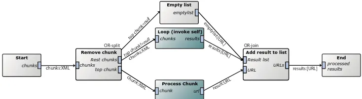
support it. To overcome this problem, an exotic workflow pattern was used, that has, to our knowledge, never been mentioned before: multi-ple instances by means of recursive workflow invocation. The pattern is presented in Figure 3.1.
Usually iteration is more efficient than tail recursion in terms of stack space and performance. This is also true for the workflow pattern pre-sented here: Each subworkflow is started in its own thread, and extra tasks have to be executed to split and combine the results. The advan-tage of this pattern is that all chunks can be processed in parallel, which is not possible using iteration. The time saved by processing all chunks in parallel is, in the case of OligoRAP, greater than the overhead that is the result of the extra tasks that are being invoked, therefore the overall performance of the workflow increases in terms of speed.
Some OligoRAP implementation workflow facts The OligoRAP
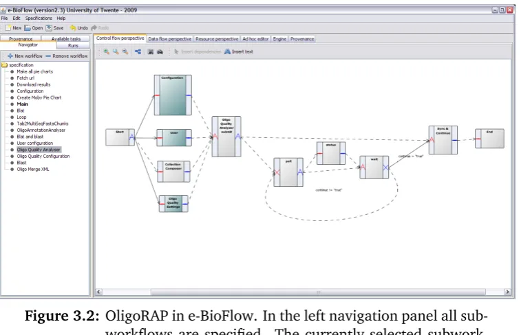
work-flow contains fifteen subworkwork-flows (plus one for the main) and a total of 149 tasks, 9 tasks on average per subworkflow. 35 tasks are composite tasks representing one of the fifteen subworkflows. A single subworkflow was used for all configuration parameters, providing a single location where all parameters can be specified. See Figure 3.2 for a screenshot of the Oligo Quality Analyser subworkflow in e-BioFlow.
3.4
Provenance implementation
In order to collect provenance data during workflow execution, a
suit-able provenance model had to be either designed or selected. In §2.2.1
28 | Chapter 3- Improvements to e-BioFlow Start chunks processed results End Rest chunks chunks Remove chunk top chunk Process Chunk chunk url
Loop (invoke self)
chunks results
Result list URLs
Add result to list
[image:44.595.130.497.192.293.2]URL Empty list emptylist top chunk=null top chunk!=null chunk :XML chunks:XML chunks:XML empt ylist:[URL] results:[URL] result:URL results:[URL] OR-split OR-join
3.4 Provenance implementation | 29
Figure 3.2: OligoRAP in e-BioFlow. In the left navigation panel all sub-workflows are specified. The currently selected subwork-flow is the Oligo Quality Analyser. It consists of several tasks for submitting, polling (which occurs in the loop) and retrieving the result of the asynchronous job.
each others’ lab journals. In workflow context, it means workflow sys-tems are able to exchange their workflow runs, even among different systems. Being designed for interoperability, the OPM is a very generic model.
Because of these reasons the OPM is a very suitable candidate. Unfortu-nately, no libraries or other direct OPM implementations exist. Therefore, e-BioFlow is improved with a new direct implementation of the OPM. This implementation can be easily adopted by other provenance aware systems, or other SWfMS. An advantage of a direct OPM implementation is that provenance data can be exported, serialized to XML or RDF for instance, without the need to translate from a different internal storage model to the OPM.
3.4.1
Requirements for provenance implementations
Groth [21] points out four non-functional requirements for provenance
30 | Chapter 3- Improvements to e-BioFlow
proposed here, based on a PostgreSQL database, meets all of these
re-quirements. Sahoo et al. [37] have taken a similar approach, using a
relational database back-end as well. The most important requirement is a functional requirement: the archive should be optimised for efficient provenance queries. A relational database implementation in PostgreSQL provides a query language for the OPM, expressed in SQL. The SQL standard defines recursive queries since its fourth dialect, ISO SQL:1999
[14]. In the sixth and latest standard, ISO SQL:2008, recursive queries
are referred to as Common Table Queries (CTE). CTE is supported in Postgres since the latest release of July 2009, version 8.4. Recursive queries can be used to query complete derivation trails, an example of this is given in§5.1.3.
3.4.2
Database Design
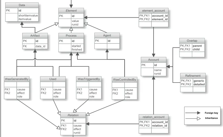
From the OPM specification, version 1.01. [31], an Entity Relationship
Diagram (ERD) was derived, which is presented in Figure 3.3. Recall §2.2.1 for an explanation of the structure of the OPM itself.
The ERD is based on the Timeless Formal Model of the OPM
specifica-tion. As a result of the 3rd Provenance Challenge workshop, the OPM
specification is currently reviewed and one of the change proposals is to remove time from the OPM specification. Instead it is suggested to put
the time formalism in a profile2, such as the one presented in§3.5. The
proposed time model in the OPM specification is indeed rather complex.
In this implementation astartedandfinishedtimestamp is added only
to processes.
Inheritance is used for the entities ELEMENT and RELATION. ELEMENT is the
supertable of ARTIFACT, AGENT and PROCESS and RELATION has subtables
USED, WASCONTROLLEDBY, WASTRIGGEREDBY and WASGENERATEDBY. The use
of inheritance allows generic queries over all elements and relations, as well as specific queries over only a certain type of elements or relations.
For each OPM relation, foreign keys are specified for the columnscause
andeffect. In the supertableELEMENTboth foreign keys reference the id
in the supertableELEMENT. In the subtables, specific references to the
cor-responding subtables are made. For example, the foreign key constraint
for the column causeof theUSEDtable states it references the id of table
2OPM Wiki - Change proposals. Last visited September 2009.http://twiki.ipaw.
3.5 Provenance Recording: an OPM-profile | 31
Relation PK id FK1 FK2 causeeffect
runid Element PK id value runid Used FK1 FK2 causeeffect
role WasControlledBy FK1 FK2 cause effect role WasTriggeredBy FK1 FK2 causeeffect
role WasGeneratedBy
FK1 FK2 causeeffect
role Process PK id started finished Agent PK id Artifact PK id FK data_id Account PK id name runid Overlap PK,FK1 PK,FK2 parent child Refinement PK,FK1 PK,FK2 generic detailed element_account PK,FK1 PK,FK2 account_id element_id relation_account PK,FK1 PK,FK2 account_id relation_id Data PK id shortitemvalue itemvalue Foreign key Inheritance Relation PK id FK1 FK2 causeeffect
runid Element PK id value runid Used FK1 FK2 causeeffect
role WasControlledBy FK1 FK2 cause effect role WasTriggeredBy FK1 FK2 causeeffect
role WasGeneratedBy
FK1 FK2 causeeffect
[image:47.595.95.461.137.362.2]role Process PK id started finished Agent PK id Artifact PK id FK data_id Account PK id name runid Overlap PK,FK1 PK,FK2 parent child Refinement PK,FK1 PK,FK2 generic detailed element_account PK,FK1 PK,FK2 account_id element_id relation_account PK,FK1 PK,FK2 account_id relation_id Data PK id shortitemvalue itemvalue Foreign key Inheritance
Figure 3.3: Database diagram (Entity Relationship Diagram) of the Open Provenance Model.
PROCESS. By similar argument, the effect column references an id of table
ARTIFACT.
The ERD in its turn is used to devise a database schema for PostgreSQL. The schema can be found in Table 3.3. The first table, T0, already ex-isted in e-BioFlow for storing input/output data in a database, instead of
keeping this data in memory during workflow execution (see§3.2).
3.5
Provenance Recording: an OPM-profile
The OPM has some limitations because of its generality. Although it is intuitive to map a workflow run to the OPM, such a mapping is not part of the OPM specification, since the OPM intends to be technology-agnostic. It is ambiguous what is actually being captured in the model, how to capture provenance data during workflow execution. To disambiguate, an OPM profile needs to be defined, that makes the mapping between an application and the OPM explicit.
Kwasnikowska and van den Bussche have proposed an OPM profile for
32 | Chapter 3- Improvements to e-BioFlow
Table 3.3: OPM Database table specification
T0 DATA(IDint,VALUE)
T1 ELEMENT(IDint sequence(ELEMENT_SEQ)not null,
VALUEvarchar(255),
RUNIDint not null,
primary key(ID))
T2 RELATION(IDint sequence(RELATION_SEQ)not null,
RUNIDint not null,
CAUSEint referencesELEMENT(ID)not null,
EFFECTint referencesELEMENT(ID)not null,
primary key(ID))
T3 PROCESS(STARTEDtimestamp,FINISHEDtimestamp)inheritsELEMENT
T4 AGENT()inheritsELEMENT
T5 ARTIFACT(DATA_IDint referencesDATA(ID)not null)inheritsELEMENT
T6 WASTRIGGEREDBY(
CAUSEint referencesPROCESS(ID),
EFFECTint referencesPROCESS(ID)
)inheritsRELATION
T7 USED(ROLEvarchar(255) not null,
CAUSEint referencesPROCESS(ID), EFFECTint referencesARTIFACT(ID)
)inheritsRELATION
T8 WASGENERATEDBY(ROLEvarchar(255) not null,
CAUSEint referencesARTIFACT(ID),
EFFECTint referencesPROCESS(ID)
)inheritsRELATION
T9 WASCONTROLLEDBY(ROLEvarchar(255) not null,
CAUSEint referencesARTIFACT(ID),
EFFECTint referencesPROCESS(ID)
)inheritsRELATION
T10 ACCOUNT(IDserial,VALUEvarchar(255),RUNIDint,primary key(ID)) T11 OVERLAP(PARENTint referencesACCOUNT(ID),
CHILDint referencesACCOUNT(ID),primary key(PARENT,CHILD))
T12 REFINES(DETAILEDint referencesACCOUNT(ID),
GENERIC int references ACCOUNT(ID), primary key
(GENERIC,DETAILED)) T13 ELEMENT_ACCOUNT(
ELEMENT_IDint referencesELEMENT(ID)
ACCOUNT_IDint referencesACCOUNT(ID),
primary key(ELEMENT,ACCOUNT))
T14 RELATION_ACCOUNT(
RELATION_IDint referencesRELATION(ID)
ACCOUNT_IDint referencesACCOUNT(ID),
3.5 Provenance Recording: an OPM-profile | 33
based on the older v1.0 specification of the OPM (where the REFINES
re-lationship was not yet defined). An implementation for this formal map-ping still needs to be designed.
Therefore, an OPM profile is proposed here that makes the mapping ex-plicit between the OPM and workflows executed by any hierarchal work-flow system. This OPM-profile is implemented in e-BioFlow.
Table 3.4 presents and explains the OPM-profile. The left, middle and right column specify the workflow events that occur, the OPM entities that are created during the event and the workflow values that are as-signed to these entities, respectively. The profile maps workflow tasks to processes, actors (services) to agents and data to artifacts. In the
event of a task being executed, a USED relation is created for each input
port, between the process and artifact corresponding to the task and data
item. The role of the USED relation is given the name of the input port.
Likewise WASGENERATEDBY relations are created in the event of a finished
task, for each output port. In the event of a control flow link being
fol-lowed between two tasks, a WASTRIGGEREDBY relation is created between
the corresponding processes. For each service that executes a certain
task, a WASCONTROLLEDBY relation is created between the corresponding
agent and process. The role of the task is assigned to the role of the
WASCONTROLLEDBYrelation.
Accounts are used to capture different levels of execution detail. For each composite task, two accounts are being created, a coarse grained and a fine grained account. The first one, containing the composite task itself, has low detail and contains the process corresponding to the composite task and all related artifacts. The second provides more detail: it contains all the processes corresponding to tasks executed by the subworkflow, but it does not contain the composite task itself. Between these two accounts, a refinement relation is specified. The two created accounts overlap the account belonging to the (sub)workflow the composite task was executed by, which can be seen as the parent account of the two newly created accounts. This parent/child relationship between accounts is captured in the overlap relation. This relationship represents a tree of accounts,
which is further referred to as theRefinement Tree (RT).
34 | Chapter 3- Improvements to e-BioFlow
Table 3.4: The OPM-profile. Mapping OPM entities during workflow execution in e-BioFlow.
Workflow Event Actions Value assignments
Main workflow
Wmainstarted
Instantiate OPM graph
Create ACCOUNT Ac1 for workflow
Wmain
TaskT part of (sub)workflowW
started
Create PROCESSP for taskT
Record start time for processP
Create AGENTAg
Create WASCONTROLLEDBY(R,Ag,P)
W cb
Create ARTIFACTAi
Create USED(Ri,P,Ai) Ui for each
in-put porti
Fetch accountAc1for workflowW Add allP,Ai,UiandW cbtoAc1 In caseT is a composite task: Create ACCOUNTAc2for taskT Add allP,Ai,UiandW cbtoAc2 Create OVERLAPS(Ac1, Ac2)
P = Task name
Ag= Agent name
R = Role name
Ai = Input data Ri = Name of
in-put porti
SubworkflowWsub
started by composite taskT,
T part of (sub)workflow
Wparent
Create ACCOUNT Ac1 for workflow
Wsub
Fetch ACCOUNTAc2of taskT Create REFINES(Ac1, Ac2)
Fetch ACCOUNT Ac3 for workflow
Wparent
Create OVERLAPS(Ac1, Ac3) TaskT part of
(sub)workflowW
completed
Fetch PROCESSP for taskT
Fetch ACCOUNTAc1for workflowW Record finish time for processP
Create ARTIFACTAi
Create WASGENERATEDBY(Ri,P,Ai) W gbi for each output porti
Add allAi,W gbitoAc1 In caseT is a composite task: Fetch ACCOUNTAc2of taskT Add allAiandW gbitoAc2
Ai = Output data Ri = Name of
out-put porti
Link followed from taskT1part of (sub)workflowW1
to taskT2part of (sub)workflowW2
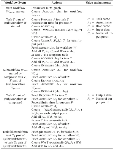
3.5 Provenance Recording: an OPM-profile | 35 jobid:int jobid:int probes:string results:string status = ”finished” status!=”finished” Select probes BLAST
status jobid jobid
jobid jobid
probes sequences results
sequences Submit BLAST
value
results View
Poll BLAST job
Fetch job Result
jobid:int BLAST Subworkflow
Composite task
[image:51.595.187.370.147.232.2]`BLAST submit’ role `BLAST poll’ role `BLAST retrieve’ role
Figure 3.4: Workflow specification performing an asynchronous BLAST job on selected probes. The BLAST task is a composite task, the subworkflow it executes is presented below. Input and output ports are labeled italic. Predicates specifying which control flow links are enabled are italic too and positioned above the corresponding edge.
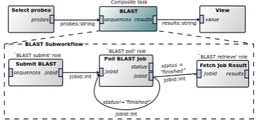
WGB(probes) WGB(jobid) WGB(status) Used(jobid) wasTriggeredBy WGB(result) Used(jobid) wasTriggeredBy WGB(status) WGB(jobid) w asT riggeredBy Used(sequ..) WGB(jobid) Used(jobid) wasTriggeredBy wasTriggeredBy Used(sequences) wasTriggeredBy Used(v alue) WGB(results) wasT riggeredBy Select
Probes BLAST View
Submit BLAST Poll BLAST job Poll BLAST job Fetch job Result ATCG TCGAC TTA Result
300 300 300
Running Finished
Bio MOBY http:// Root account
Account of composite task BLAST
Refined account of composite task BLAST
WCB(BLAST submit) Bio MOBY http:// WCB(BLAST poll) Bio MOBY http:// WCB(BLAST poll) Bio MOBY http:// WCB(BLAST retriev e)
[image:51.595.114.447.376.575.2]36 | Chapter 3- Improvements to e-BioFlow
Example Figure 3.4 presents a screenshot of a workflow that executes an asynchronous BLAST job. The first task selects probes from an oligo library. The second task, BLAST, is a composite task that BLASTs all probes. The results are visual