Experimental Investigation and CFD Analysis on
Effect of Turbulaters on Performance of Heat
Exchanger
Indrajeet kumar1Rkdf ist,bhopal
Abstract: Heat exchanger is an important device in all the thermal systems. The heat exchanger is widely used equipment in different industries such as process, petroleum refining, chemicals, pharmaceutical and paper etc. After studying different literature about heat exchanger and double pipe heat exchanger problem is identified as to perform simulation and experimental investigation of double pipe heat exchanger with inner twisted tape inserted different mass flow rate. The system has followed different types of flow arrangement and geometric dimension with circular tape to attain heat transferred in experimental result and compare with simulation result. The objective of these experiments is Performance analysis of double pipe heat exchanger with inner and outer twisted tape at different mass flow rate. The experimental set up consists of double pipe heat exchanger experiment. The apparatus includes tube-within-a-tube heat exchangers and twisted tape type inserted threaded thermocouple at each end, a water pump and electric motor. These methods used to find out the heat transfer rate from the surface and related temperature of fluid motions also used to find the effectiveness..
I. INTRODUCTION
Heat exchangers are widely used in chemical, power generation and petroleum refining industry. Shell and tube heat exchanger have the ability to transfer large amount of heat in relatively low cost, serviceable designs. The important variable in reducing the size and cost of a heat transfer device are pressure drop and heat transfer coefficient. Therefore, it is good to developed method to improve the heat transfer coefficient. The twisted tape insert as flow turbulator’s have been widely applied due to their promising performance. Many researchers have reported their influence of tube insert on heat transfer improvement.The promising challenge for design of heat exchanger is to reduce the pumping power while increased heat transfer rate. Therefore it is essential to develop theory and technique about increased heat transfer in the double pipe heat exchanger to optimize the performance of heat exchanger. The presence of twisted tape lowers the hydrodynamic and thermal boundary layer thickness, leading to greater convective heat transfer. Though pumping power may increase meaningfully and ultimately the cost of pumping is more. Therefore to achieve a desired heat transfer rate with minimum pumping power, the design of twisted tape with proper geometry is necessary.Twisted tapes are normally inserted into the tube to generate swirl motion of fluid for greaterheat transf This also leads to improve flow velocity, thermal boundarylayer,hydrodynamic boundary layer, heat transfer rate, fluid mixing. However more pumpingpower is required when twisted tapes are inserted to inner tube. Classification of improvement method- Heat removal improvement method mention to the development of thermo hydraulic performance of heat exchanger .These improvement method is categorized in generally three categories. They are as below
A. Active method
In these Methods, exterior power is used to effect the need flow statementand related important in rate of heat transfer.
B. Passive Method
These methods do not necessary have any direct input of exterior power.
C. Compound Method
A compound important method is the one wherever more than one ofthe above stated method is used in mixture by the purpose of further improving the rate of heat transfer.
II. METHODOLOGY
The study the heat transfer performance of heat exchanger with and without insert twisted tape different geometry. Calculation of its heat transfer performance.
Heat transfer coefficient for all cases. Nusselt number for all cases. Reynolds Number for all cases.
.compare in mode of the result of found from experimental analysis and simulationtwisted tape type insert
A. Proposed Experimental Set-Up
Fig 3.5
1) Hot water tank 7. Test section 13. Control panel
2) Hot water pump8. Hot water outlet 14. Temperature indicator
3) By pass valve 9. Cold water tank 15. Temperature controller
4) Flow control valve 10 . Cold water pump16. Inverted u- tube manometre
5) Rotameter 11. Cold water inlet 17. Stand
6) Hot water inlet 12. Cold water outlet 18. Table
B. Components With Specification
The following is a list of all pieces of equipment and their specifications for the double-pipe heat exchanger.
1) Double-Pipe Heat Exchange
Inside pipe Material copper Outside pipe matrial steel Length 1.4m INSIDE PIPE
inside pipe dia 0.0198m outside pipe dia 0.0028 m outside pipe thickness 0.003m HOT WATER
COLD WATER Pass 1
2) Valves
Ball Valves
Location: Process Valves, Tank Valve, Drain Valve, Bypass valves
3) Temprature indicating controle
Input ; RTD –PT100 wire range 0 to 200degc
Display: 31/2 digit red led 13 mm Height Accuracy: 1%F.S.
Set point: 1 Potentiometric Output: INO/NC, 3A Control mode: ON/OFF Power: 230VAC 50Hz +/- 10%
Size: 96 x 96 x 85 mm DIN ABS Cabinet Panel cutout: 92 x 92mm
4) Multipoint Temperature Indicator
Input: RTD-PT100, 3 Wires
Display: 3 1/2 Digit Red Led 3mm Height Range: 0 to 400 Deg.
Power: 230V AC, 50 Hz.
Size: 96 x 96 x 80 mm DIN Panel Cutout: 92 x 92 mm
Model: MPTI
5) Electrical Heater Type: Emersion type Body: SS304
Capacity: 1.5KW
Power: 230VAC 50Hz
6) Pumps
Type: Centrifugal Capacity: 1/5HP Discharge: 2000LPH Foot mounting
Power: 250VAC 50 Hz Size: 1”
7) U tube manometer
MOC: Acrylic
Range: 250 – 0- 250mm WC
8) Temperature Sensor
Type : RTD-PT100 3 wire Assembly: Transition type Range: 0 to 300Deg C
Diameter: 6mm
Length: 100mm Cable:3mtr. Teflon/Teflon Cable
9) Rota meter
Float : SS316
10) Power relay
Power: 250VAC 50Hz Output: 1NO
Size: Wall mounting
11) Tanks in MS with powder coating Size: 400 x 350 x 350mm
C. Formulae use
1) Properties of hot water : Calculated at mean bulk temperature Tbh = Th1 + Th2
2 Where
Tbh = mean bulk temperature hot water in °c Th1 = inlet temperature of hot water in °c Th2 = outlet tempratue of hot water in °c Tbh= 335+325
2 = 330°c
2)Properties of cold water
Tbc = Tc1 + Tc2 2 Where
Tbc = mean bulk temperature cold water in °c Tc1 = inlet temperature of cold water in °c Tc2 = outlet tempratue of cold water in °c Tbc= 300+308
2 = 304°c
3) Heat given by hot water
Qh= mh. Cph(Th1 –Th2) Where
Qh= heat given by hot water in kw mh= mass flow rate of water in kg/s
cp= specific heat of water at constent pressure in k j/kg°c Th1= inlet temperature of hot water in °c
Th2= outlet temperature of hot water in °c Qh= 0.1667x4.187(335-325)= 6.9797kw
4) Heat given by cold water
Qc= mc. Cpc(Tc2 –Tc1) Where
Qc= heat given by cold water in kw mc= mass flow rate of water in kg/s
cp= specific heat of water at constent pressure in k j/kg°c Tc1= inlet temperature of cold water in °c
Tc2= outlet temperature of cold water in °c Qc= 0.1667x4.187(308-300)= 5.5837 kw
5) Avrage heat transfer Qavg = Qh + Qc 2
Qc= heat given by cold water in kw
Qavg = 6.9797+5.5837 2
= 6.2817 kw
6) Overall heat transfer coefficient
Qavg = U.As. ΔTm Where
U=overall heattransfer coefficient between two fluide w/m2 °c AS= effective heat transfer area m2
ΔTm = approprimate means of temperature difference AS= (π/4) × di2
3.14 (0.0198)2 =0.0003077 4
ΔTm= (ΔT1- ΔT2)
ln(ΔT1/ ΔT2)
= (335- 325) = 2.2723°c
ln(335/ 325)
Qavg = U.As. ΔTm
6.2817 kw =Ux0.0003077x2.2723 U= 8984.295KW/m2°c
7) Reynolds number
Re = pvdi µ
p= density of water v= velocity of water di= diameter of inner pipe µ = viscosity of water v= m
PAS
V= 0.1667 =0.5417m/s
1000x0.0003077
Re= 1000x0.05417x0.0198
8.90x10-4
=12052.67
Δp=pgΔh
= 1000x9.8x0.132 =1293.6N/m2 For mass florate =0.1667kg/s
Re=12052.67
Nui = 0.023(Re) 0.8 (Pr) 0.3
Nui= 0.023(12052.67)0.8(5.42)0.3 = 70.27 f = 16/Re
For mass florate =0.1667kg/s Re=12052.67Nui= h*di k
= 4189.66x0.0198 = 138.26 0.6
f= Δpdi 2PLv2
f= 1294.6x0.0198 2x1000x1.4x0.54172 = 0.03197
Same as calculate for all mass flow rate
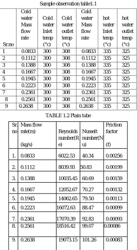
[image:6.612.170.444.221.722.2]Sample observation table1.1
TABLE 1.2 Plain tube Sr.no Cold water Mass flow rate Cold water Inlet temp (°c) Cold water outlet temp (°c) Cold water Mass flow rate hot water Inlet temp (°c) hot water outlet temp (°c) 1 0.0833 300 308 0.0833 335 325 2 0.1112 300 308 0.1112 335 325 3 0.1388 300 308 0.1388 335 325 4 0.1667 300 308 0.1667 335 325 5 0.1945 300 308 0.1945 335 325 6 0.2223 300 308 0.2223 335 325 7 0.2361 300 308 0.2361 335 325 8 0.2561 300 308 0.2561 335 325 9 0.2638 300 308 0.2638 335 325
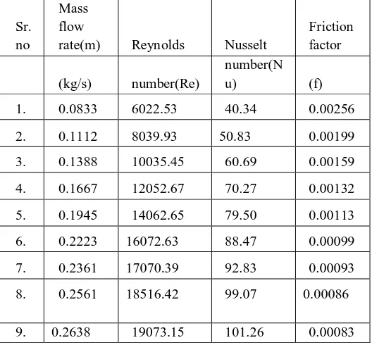
Sr. no
Mass flow
rate(m) Reynolds Nusselt
Friction factor (kg/s) number(R e) number(N
u) (f)
1. 0.0833 6022.53 40.34 0.00256
2. 0.1112 8039.93 50.83 0.00199
3. 0.1388 10035.45 60.69 0.00159
4. 0.1667 12052.67 70.27 0.00132
5. 0.1945 14062.65 79.50 0.00113
6. 0.2223 16072.63 88.47 0.00099
7. 0.2361 17070.39 92.83 0.00093 8. 0.2561 18516.42 99.07 0.00086
Table 1.3 Twist tape
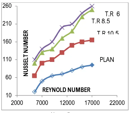
Graph represent between Reynolds number and nusselt number of twist tape or without twist tape inserted in heat exchanger In below figure
T.R represent the twist ratio
Twist ratio = pitch Width of tape
Above figure 10
60 110 160 210 260
2000 7000 12000 17000 22000
N
U
SS
EL
T
N
U
M
B
ER
REYNOLD NUMBER
PLAN T.R 10.5 T.R 8.5
T.R 6
Sr. no
Mass flow
rate(m) Reynolds Nusselt
Friction factor
(kg/s)
number(R e)
number(N
u) (f)
1. 0.0833 6022.53 69.13 0.12489
2. 0.1112 8039.93 97.27 0.07012
3. 0.1388 10035.45 115.18 0.045004
4. 0.1667 12052.67 138.26 0.03197
5. 0.1945 14062.65 148.4 0.0227
6. 0.2223 16072.63 153.1 0.017548
7. 0.2361 17070.39 161.8 0.011548
8. 0.2500 18516.42 165.4 0.0132
C. Above Figure
plot between Nusselt number and Reynolds number for without twist tape and twisted tape with various twisted ratio inserted ,concludes that nusselt number and Reynolds number . Nusselt number rise with rise in reynolds number .hence rate of convective heat transfer is more with higher reyonlds number . Further ,it can concluded that , twisted tapes with higher twist (with lesser twist ratio) give increase nusselt number for particular reynolds number . heat transfer rate is batter with twisted tape of lower twist ratio.
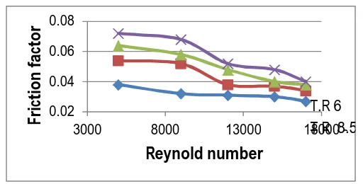
Graph between renold number and fraction factore is shown below
Heat exchanger modelling and analysis are carried out on ansys workbench Above figure plot drawn between factor of friction and
Reynolds number with varying twisted tape ratio ,one can easily observe the change fraction factor with varying twisted ratio with increase in fraction , Reynolds number also increase.
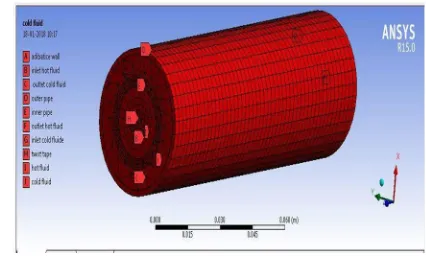
D. Cfd analysis
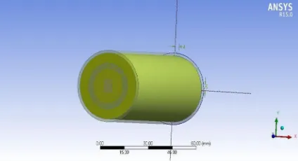
[image:8.612.184.440.169.299.2] [image:8.612.215.400.383.525.2]1) Modelling: Start ANSYS WORKBENCH
Fig model of heat exanger First we describe part of model with dimension
2) wisted Tape
Fig model of heat exanger
Dimension of twisted tape Length of twist tape 1.4m Pitch of twisted tape 4.2mm
0.02 0.04 0.06 0.08
3000 8000 13000 18000
Fr
ic
ti
o
n
f
ac
to
r
Reynold number
Cross section of twisted tape rectangular(0.7x0.5)
Procedure for twisted tape For this open the Ansys workbench ,and select the x-y plane ,then drawing rectangle 0.7*0.5 ,after that again taken y-z
plane making second sketch drawing line start with centre of rectangle with length is 1.4m and exist 2d work bench go modelling sweep command use , for this select the first profile as rectangle then select line as path, then go twist and given the pitch 40 mm, the generate
diameter of the tube : 0.0198m
tube thickness : 0.0028m
D. Procedure
For this select x-y plane and making circle with diameter is 0.0198m,again drawing circle with diameter 0.0226m in same sketch ,then extrude with frozen with height 1.4m the generate
[image:9.612.231.408.246.363.2]Fluid filing in outer tube Fill outer tube with cold fluid as shown as belo Then we describe of outer tube filling fluid figure shown in below
Fig 3.1211 model of outer tube with cold fluid filling
E. Use Boolean operation
[image:9.612.207.419.398.513.2]Here subtract Boolean Operators is used from outer fluid to inner fluid as shown in below
Fig 1.13 model after boolen operation
F. Meshing
[image:9.612.223.400.576.658.2]Fig 3.14 meshing of model Mesh outer edge
Fig 3.15 Mesing of outer Edge
All part meshing shown below
Fig 3.16 mesing of whole model 1.no of node s30933 2. elements no 58496
G. Processing
After the completion of meshing the design in ANSYS Fluent .in fluent boundery conditions are given as per requirement and solution is initialized and calculation are iterated After the calculation is converged the contours are to be plotted
The Boundary conditions are under taken below Fluid domain is to be specified
Temperature At inlet
Hot fluid – water (335k) Cold fluid – water (300k
[image:10.612.51.519.453.703.2] [image:10.612.180.393.569.697.2]In the analysis report the mainly reynolds number, pressure, velocity, temperature contour to be viewed the result obtain are to be tabulated
Boundary specifications
Outer surface: Adiabatic outer wall Twist tape: wall
Outer pipe: :wall Inner pipe : : wall
Cold water inlet: : velocity Hot water inlet : : velocity
Cold water outlet : : pressure outlet Hot water outlet : : pressure outlet Cold domain : :mass flow Hot domain : :mass flow
II. RESULTS AND DISCUSSION
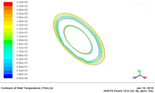
[image:11.612.199.415.302.525.2]First we compare temperature of cold fluid outlet with twist tape and without twist tape shown in below With twist tape
Fig 4.1 temprature of hot fluid outlet with twisted tape inserted
B. Without twist tape
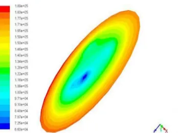
[image:11.612.189.448.561.717.2]Fig 4.3 Reynolds number at inlet in heat exchanger with twist tape
Fig 4.4 Reynolds number at outlet in heat exchanger with twist tape
in the above figure we can observe that the Reynolds number is increasing from inlet to outlet of the heat exchanger to the outlet of heat exchanger .this the because of the reason that during the flow of fluid over the twisted tape a disturbance is created in flow thus turbulence is created this result is increase of the Reynolds number
[image:12.612.205.389.511.715.2]Fig 4.6 Reynolds number at outlet in heat exchanger without twist tape
In above two figure the reynolds no of the hot fluid at inlet and outlet of heat exchanger .we observe that there is no much difference in the value , they remain almost constant .this is due to no turbulent in the flow
[image:13.612.179.434.526.712.2]
Fig 4.8 velocity vector of heat exchanger with twisted tape Sr.no
Mass flow
rate(m) Reynolds Nusselt
Friction factor
(kg/s) number(Re) number(Nu) (f) 1. 0.0833 6022.53 69.13 0.12489 2. 0.1112 8039.93 97.27 0.07012 3. 0.1388 10035.45 115.18 0.045004 4. 0.1667 12052.67 138.26 0.03197 5. 0.1945 14062.65 148.4 0.0227 6. 0.2223 16072.63 153.1 0.017548 7. 0.2361 17070.39 161.8 0.011548 8. 0.2500 18516.42 165.4 0.0132
The above figure shown that the velocity & direction of the fluid element during the flowing of heat exchanger (with twist tape). We can observe that there is a rise in velocity of the fluid element when moving from inlet to the outlet this is due to the swirl created by the twisted tape.
[image:14.612.175.439.157.402.2]The result obtain from CFD analysis are shown below
Table 4.1 Plain tube:result without twist tape inserted
Comparision is made between CFD analysis and experimental analysis for with and without twisted tape inserted
III. CONCLUSION
CFD analysis is carried out by taking double pipe heat exchanger with cold and hot fluids with different boundary conditions by incorporating twist tape inserts .It can be concluded as follows: By using passive techniques that is by inserting twist tape inserts the heat transfer enhancement increased by 10-15% with the cost of reasonable allowable pressure drop .In this report we achieved enhancement of heat transfer effectively. Future work may be extended to:
A. Combination of techniques may be used to enhancement of heat transfer coefficient by compound techniques
B. Reduce the width of twist tape inserts with low Reynolds number
C. By varying low Reynol
REFERENCES
[1] Aha s.k, Heat Transfer Intensification in U-bend Double Pipe Heat Exchanger using Twisted Tape InsertsInternational Journal of Innovative Research in Science, Engineering and Technology, Augest 2015 ,vol 51333- 134
[2] ard Eiamsa- experimental investigations of heat transfer enhancement in double pipe heat exanger using twisted tape dense wire mesh insert, 2012 5 –
[3] Ebru Kavak Akpina Modeling of Climatic Parameters and Determination of Climatic Differences in the City of Elazig-Turkey and its Close Regions Journal of Environmental Protection, 2010, 1, 41-52
[4] Kannan .M rainfall Forecasting using data mining technigue international journal of engineering & Technology , t 2010 vol 2 , 397-40
[5] Kiran K. Lalit ,CFD Analysis on Twisted Tape Heat Exchanger with Hybrid Nano Particle, International Journal for Research in Applied Science & Engineeringechnology (IJRASET) April 2017 Volume
[6] Maddah Heydar Effect of Twisted-Tape Turbulators and Nanofluid on Heat Transfer in a Double Pipe Heat Exchanger Journal of Engineering, 2014
[7] Mangtani Mukesh , EFFECT OF TWISTED-TAPE INSERTS ON HEAT TRANSFER IN A TUBE—A REVIEW [7] international journal of mechanical engineering and robotic research , April 2015 Vol. 4
[8] Naveen.s CFD Analysis of Concentric Tube Heat Exchanger Using Twisted Tapes, International Journal of Advance Research, Ideas and Innovations in Technology.,2017, 870 -87
[9] Prajapati Om Shankar Heat Transfer Behaviour of Nano-fluid at High Pressure Journal of Materials Science Surface Engineering Vol. 1 2013, pp. 1-3. Vo [10] Sommers and Jacobi A review on polymer heat exchangers for HVAC&R applications, international journalof refrigeration (2009) 763–779
Sr. no
Mass flow
rate(m) Reynolds Nusselt
Friction factor
(kg/s) number(Re)
number(N
u) (f)
1. 0.0833 6022.53 40.34 0.00256
2. 0.1112 8039.93 50.83 0.00199
3. 0.1388 10035.45 60.69 0.00159
4. 0.1667 12052.67 70.27 0.00132
5. 0.1945 14062.65 79.50 0.00113
6. 0.2223 16072.63 88.47 0.00099
7. 0.2361 17070.39 92.83 0.00093
8. 0.2561 18516.42 99.07 0.00086