794
©IJRASET: All Rights are Reserved
Numerical Analysis of Rectangular Ribs
Roughed Solar Air Heater: A CFD Based Study
Himanshu Pandya1, Shankar Lal Suthar2, Gaurav Purohit3
1, 2, 3
Aravali Institute of Technical Studies, Udaipur, Rajasthan, India
Abstract: A perfect design can be a most effective factor in terms of cost for a solar air heater. As studied, there are so many techniques have been proposed to enhance the solar air heaters’ efficiency by adding turbulence promoters or by improving designing concepts. The aim of this research is to find best solution to get rid of the inconvenience results from the mostly used solar air heater designs with general heat transfer enhancement techniques. Isn this study a design has been proposed with rectangular roughness at the absorber plate and compared with smooth duct 20 mm x 100 mm x 560 mm (Thakur et. al., 2016) experimental and CFD simulation based data. A computational model has been prepared to study the effect or roughness in the solar air heater under the different mass flow rates or Reynolds Number range 5000-20000. The performance was evaluated in terms of thermal and effective efficiency for Jaipur, India location. The Rosseland Solar Radiation model was used for the study to find out the different seasonal effect on the duct. The validation of the present study is done with experimental data of Thakur et. al., 2016. It is observed that the solar air heater with roughed rectangular ribs is more efficient as compare to simple structure and it is considerably higher heat transfer rate in the month of June among 5 different months in comparison with the efficiency range of the conventional smooth flat plate heaters for similar operating conditions.
Keywords: Solar Air Heater, Roughed, CFD Simulation, Ribs, Seasonal Effect
I. INTRODUCTION
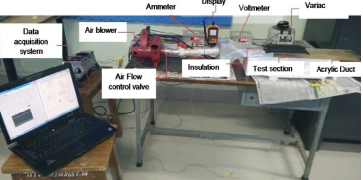
[image:1.612.128.499.535.719.2]These days, the reliance on solar energy based on the expanding need of thermal energy in private sectors and in some industrial has turned into a dire prerequisite. The working proficiency of the solar ducts are being used to utilized for solar energy that can be converted into thermal energy. This efficiency is defined as absorbing incident solar radiation, converting it to thermal energy and delivering this last to a heat transfer medium with minimum losses (Keguang Yaoa 2015). Increase of convective heat exchange of a rectangular channel with the help of astounds/ribs has been a typical practice in the previous couple of years. This idea is generally connected in improving the thermo-hydrodynamic productivity of different modern applications, for example, heat power plants, heat exchangers, cooling segments, fridges, synthetic handling plants, car radiators and sun oriented air radiators [1]. Sun powered air heater is a gadget used to enlarge the temperature of air with the help of heat separated from sun-based vitality. These are modest, have basic plan, require less support and are eco-accommodating. Accordingly, they have real applications in flavouring of timber, drying of rural items, space heating, relieving of earth/solid structure parts and restoring of modern items [2, 3]. Saini and Saini [5] tentatively examined completely created violent stream in an unevenly warmed and misleadingly roughened rectangular pipe.
795
©IJRASET: All Rights are Reserved
The conduit was secured with the assistance of a safeguard plate that was fused with extended metalwork. Liou T. M [7] directed tests on a misleadingly roughened rectangular pipe warmed from the top. Intermittently rehashed game plan of slight wires, transverse to the stream heading, effectively enhanced the harshness of the safeguard plate. The thermohydraulic execution at ideal conditions was seen when the harshness Reynolds number was 24. Mahboub et. al. (11) An energy and exergy study has been done Gupta D et al. (2011) on a double pass flat plate solar air collector with and without porous medium embedded inside the lower channel of the collector. The obtained results show that employing porous medium can increase the thermal efficiency of the collector of more than 30%, while a second law analysis shows that the friction with the porous medium can also increase the pressure drop in the air.
II. GEOMETRYSELECTION
The Computational Fluid Dynamics model is of different solar air heater were modelled. CFD modelling was done by considering the insulated boundary conditions a part from absorber palate and inlet and outlet sections. The model was created in ANSYS Design Modeler and meshed in ANSYS Mesh Model with Mesh Sensitivity Analysis. The transient CFD analysis was done in ANSYS FLUENT to validate the code. A seasonal effect study also performed for best Solar Air Heater Design.
A. Geometry Specifications
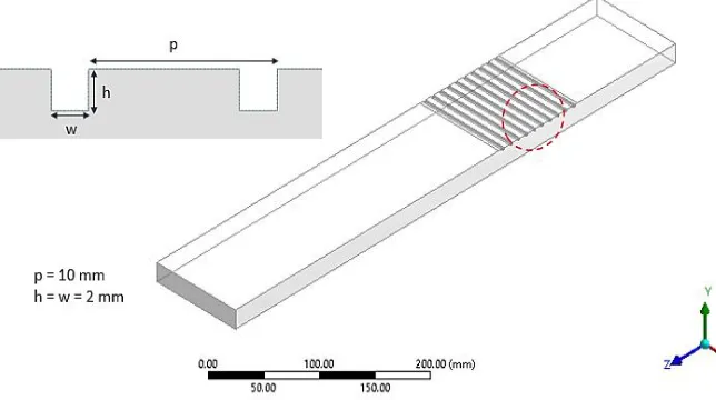
[image:2.612.148.472.341.486.2]This section presents the details of computational model with design parameters rectangular acrylic duct of 560 mm × 100 mm × 20 mm taken from Thakur et al. [4] as the CFD analysis was performed to simulate the results of total heat transferred and pressure drop within the duct. ANSYS Design Modeler was used to create the geometry. The different designs of solar air heater as shown figures 1.1 and figures 1.2. The detailed design parameters are shown in table 1.1.
Figure 1.2 Compuational Model of Smooth Duct Solar Air Heater.
[image:2.612.145.467.525.705.2]796
©IJRASET: All Rights are Reserved
TABLEI.BASICDESIGNPARAMEERS
Parameters Smooth Rectangular Ribs Unit
L 560 560 mm
H 20 20 mm
W 100 100 mm
p 10 10 mm
w 2 mm
h 2 mm
Dh 0.33 0.33 mm
III.CFDMODELING
CFD is a branch of Fluid Dynamics which deals with the analysis of problems involving fluid flow and heat transfer. It uses numerical methods and algorithms to solve and analyse problems. Computational fluid dynamics is applied to simulate and analyse the behaviour of fluids in various systems. The major advantage of numerical methods is that, the problem is discretised based on certain parameters and solved. A mathematical model is generated, which represents to actual physical system and then it can be solved and analysed. CFD is concerned with the numerical simulation of fluid flow, heat transfer and related processes such as radiation. The objective of CFD is to provide the engineer with a computer-based predictive tool that enables the analysis of the air-flow processes occurring within and around different equipment, with the aim of improving and optimizing the design of new or existing equipment. In this case the study the CFD solver FLUENT by ANSYS is used.
A. Governing Equations
In CFD, mainly three basic governing equations have used. It is known as Continuity equation, Navies-stock equation and Energy equation. Physical fundamental of each equation is different.
1) Conservation of Mass: It states that sum of all mass flowing in and out per unit time per unit volume is equal to change of mass due to change in density per unit time per unit volume.
(1) In compact vector form notation
(2)
Above show the unsteady three-dimension continuity equation. It is express law of mass conservation at each point in fluid flow and must satisfied at every point in a fluid field.
2) Conservation of Momentum: According Newton second law of motion is that the rate of change in momentum is directly proportional to the unbalanced force acting on it, in the direction of force. Useful forces consider that are effect fluid particle
a) Surface forces (like pressure forces and Viscous forces) and
b) Body forces (like Gravity force, Centrifugal force, Carioles force and Electromagnetic force)
Navies (1823) derived expression of motion equation for viscous fluid from molecular consideration. Stokes is also derived motion equation for viscous fluid in different manner. Therefore, the basic equation which governs fluid flow known as navies-stokes equation.
(3)
Above show navies-stokes equation in x- direction. In left hand side inertia term is show and in right hand side pressure, viscous and body force terms. Pressure and viscous are retard fluid flow.
In y and z direction
(4)
797
©IJRASET: All Rights are Reserved
3) Governing Equation Of Conservation Of Energy: Energy equation derived by first law of thermodynamic. According to this law rate of change of energy inside fluid element is equal to sum of net flux of heat into fluid element and rate of work done on fluid element due to body and surface forces. The energy of fluid(E) is equal to sum of internal energy (i), kinetic energy 1/2 (u2 + v2 + w2), potential energy. So energy equation is
(6) Here
E = i + 1/2 (u2 + v2 + w2)
Above show the energy equation in non-conservation form. It is apply to a moving fluid element. Fluid motion in three dimensions is described by five partial differential equation that is mass conservation, three momentum equation and energy equation.
B. Data Reduction
The CFD Numerical Modeling data like air and plate temperatures are noted under quasi steady-state conditions for different values of Reynolds number (Re) or mass flow rate (MFR). Different Nusselt numbers (Nu) are used to see the effect of roughness geometry and operating parameters on heat transfer. Using the temperature data obtained from CFD modeling, the average heat transfer coefficient h is computed by applying energy balance.
Q = m.Cp (To –Ti) = hA(Tw –Tm) (1)
H = (Q/A)/(Tw –Tm)= q/(Tw –Tm) (2)
where,
Ti is inlet air temperature
Tw is the absorber plate average temperature, which is the arithmetic mean of outlet air temperature Tm is mean fluid temperature (i.e. arithmetic mean of Ti and To)
The average Nusselt number is given by
Nu= (h * Dh)/k (3)
For the above stated calculation, the thermo-physical properties of air are evaluated at mean film temperature (i.e. arithmetic mean of Tw and Tm).
TABLEII.THERMO-PHYSICALPROPERTIESOFMATERIALUSEDFORCFDMODELING
Material Density
(kg/m3)
Specific Heat (J/kg.K)
Thermal Conductivity (W/m.K)
Viscosity (Ns/m2)
Air 1.225 1006.43 0.0242 1.7894e-05
Aluminum 2719 871 202.4 -
Wood 700 2310 0.173 -
Glass 2500 750 1.15 -
C. Turbulence Model Selection and Grid Test
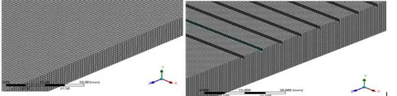
[image:4.612.115.501.472.554.2]The grid size was varied from 50000 elements to 1200000 elements for all duct types. The temperature drop variation at outlet was noted down for a particular monitor point at outlet. Not much variation was observed across the variation of the grid size after no of elements 512127, 1048373, 1099383, 1178373 for smooth, circular, parabolic and rectangular roughness type duct respectively.
[image:4.612.122.511.615.709.2]798
[image:5.612.133.492.134.358.2]©IJRASET: All Rights are Reserved
Fig. 1.5 shows that as the Reynolds number increases, the Nusselt number is also to be increased for all the three turbulent models. The flow became here more turbulent and hence the heat transfer rate increased that is the reason Nusselt number increases as the Reynolds number increased. As shown in Fig. 6.1 the turbulent model that was the closest to Thakur et. al. [4]’s experimental data is considered as best that would be RNG-k-epsilon.
Figure 1.5. Selection for Turbulence Model
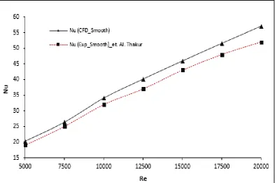
D. CFD Code Validation
[image:5.612.115.511.454.715.2]In present study the smooth air duct is considered and validated with the experimental data of the Thakur et al. [4]. In the validation of the code the smooth duct of design parameters 560 mm × 100 mm × 20 is considered. The geometry is used only for the validation of the code. The present CFD study for frication factor and total heat transfer rate are validated with the experimental and CFD Thakur et al. [4]. as shown in figure 1.6.
799
©IJRASET: All Rights are Reserved
IV.RESULTANDDISCUSSION
In present study, a comparative study is done for different solar air duct having roughness at absorber plate. A smooth solar air duct is validated with Thakur et. al. [] and optimization or enhancement is done by optimizing design parameters. Different roughed duct with circular, parabolic and rectangular roughness is investigated and compared to each other. The comparative study with heat flux of 1000 W/m2 on absorber plate is done for all four designs. It is found that the duct with rectangular roughness improves maximum the heat transfer rate as compare all rest three designs.
A. Effect of Ribs or Roughness in Duct
The physics concept behind using the ribs in Solar Air Duct n can be understood by the enhancement in Heat Transfer rate. When the different configuration ribs are formed, the flow takes place along the rib length and as such laminar sub-layer remains intact. With no flow separation, the heat transfer rate and hence the performance of solar air heater is unlikely to increase. Slight increase may occur due to increase in surface area because of the provision of ribs on the surface. If the ribs or roughen is considered as rectangular it increases the surface areas as well as the turbulence due to sharp boundary layers.
B. Effect of Ribs or Roughness in Duct
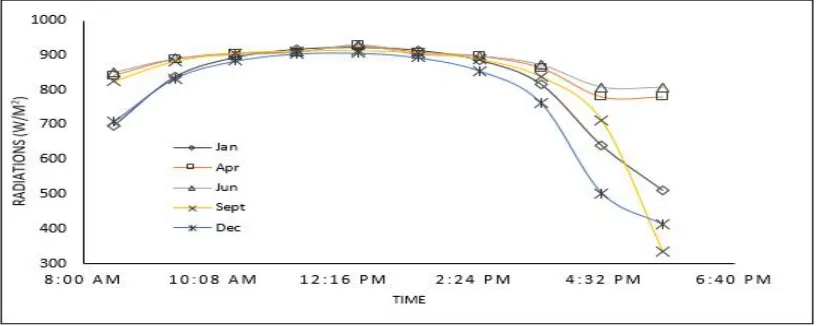
[image:6.612.110.518.341.504.2]The rectangular roughness enhanced the heat transfer rate on average 50% more as compare to other rough nesses used like parabolic and circular. The rectangular roughness Duct is further investigated by using radiation model in ANSYS Fluent 18.2. The DTRM (Discrete Transport Radiation Model) is used to formulate the seasonal effect in heat transfer rate. The irradiation values are recorded from ANSYS Fluent database. The seasonal effects are recorded for mass flow rate 0.00543 kg/ sec or Reynolds Number 5000 only. The longitude and latitude are considered for Jaipur, Rajasthan Location.
[image:6.612.110.515.505.700.2]Figure 1.7. Solar Irradiation Values
800
©IJRASET: All Rights are Reserved
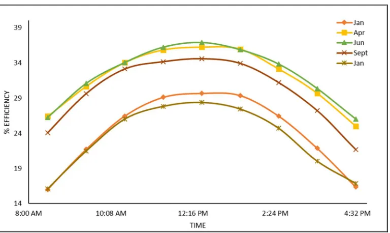
[image:7.612.124.499.81.322.2]Figure. 1.9. Variation in Outlet Temperature different months
Figure. 1.10. Total Efficiency Temperature different months
[image:7.612.117.501.349.578.2]801
[image:8.612.205.409.354.489.2]©IJRASET: All Rights are Reserved
Fig. Variation in Turbulence Kinetic Energy for Re =5000 in Roughed Duct
Fig. Velocity Vector Profile for Re =5000 in Smooth Duct
Fig. Velocity Vector Profile for Re =5000 Duct with Rectangular Rib
V. CONCLUSIONS
The present experimental work suggests that the performance of a conventional solar air heater can be improved with maximum surface of ribs instead of a conventional absorber sheet, perforated cover. To best of our knowledge, the proposed model for the solar air heater is tested for the very first time and it is found that it performs with a higher efficiency compared with other studies available in the literature.
For future studies, it is suggested to perform some experiments on a solar air heater with covers that have various hole numbers on them. The number, arrangement and diameter of the holes can be changed to see their effect on the collector efficiency. Also, different material with various geometries can be used instead of an absorber plate.
A. The present study consists with comparative analysis of solar Air duct for different ribs on absorber plate.
B. A reference model is take from the Thakur et. al. [4] and investigated with CFD techniques.
C. In the present study smooth air duct, circular roughness duct, parabolic roughness duct and the rectangular roughness duct are
investigated and it is found that the most effective ribs on the absorber plate are rectangular.
D. The actual radiation conditions are tested on the best performance air duct model.
E. Different seasonal effect for heat transfer rate or outlet temperature are investigated for best efficient model (Rectangular Ribs
802
©IJRASET: All Rights are Reserved
REFERENCES
[1] S. Keguang Yaoa, Tong Lib, Hanzhong Taoa,b, Jiajie Weia, Ke Fenga, Performance evaluation of all-glass evacuated tube solar water heater with twist tape inserts using CFD, Energy Procedia 70 ( 2015 ) 332 – 339.
[2] Tabish Alam, Man-Hoe Kim, Heat transfer enhancement in solar air heater duct with conical protrusion roughness ribs, Applied Thermal Engineering, S1359-4311(17)31394-7.
[3] M.S. Manjunath , K.Vasudeva Karanth , N.Yagnesh Sharma, Numerical Investigation on Heat Transfer Enhancement of Solar Air Heater using Sinusoidal Corrugations on Absorber Plate, International Journal of Mechanical Sciences, S0020-7403(17)32390-1.
[4] Deep Singh Thakur, Mohd. Kaleem Khan, Manabendra Pathak, Solar Air Heater with Hyperbolic Ribs: 3D Simulation with Experimental Validation, Renewable Energy, S0960-1481(17)30500-1.
[5] Prasad B. N., Behura A. K. and Prasad L., 2014, Fluid flow and heat transfer analysis for heat transfer enhancement in three sided artificially roughened solar air heater, Solar Energy, 105: pp. 27-35.
[6] Saini S. K. and Saini R. P., 2008, Development of correlations for Nusselt number and friction factor for solar air heater with roughened duct having arc-shaped wire as artificial roughness, Solar Energy, 82(12): pp. 1118-1130.
[7] Liou T. M. and Hwang J. J., 1993, Effect of ridge shapes on turbulent heat transfer and friction in a rectangular channel, International Journal of Heat and Mass Transfer, 36(4): pp. 931-940.
[8] Gupta D., Solanki S. C. and Saini J. S., 1993, Heat and fluid flow in rectangular solar air heater ducts having transverse rib roughness on absorber plates, Solar Energy, 51(1): pp. 3137.
[9] Saini R. P. and Saini J. S., 1997, Heat transfer and friction factor correlations for artificially roughened ducts with expanded metal mesh as roughness element, International Journal of Heat and Mass Transfer, 40(4): pp. 973-986.
[10] Karwa R., Solanki, S. C. and Saini, J. S., 1999, Heat transfer coefficient and friction factor correlations for the transitional flow regime in rib-roughened rectangular ducts, International Journal of Heat and Mass Transfer, 42(9): pp. 1597-1615.