Design of a 3-6 Hexapod Platform Sensor Using
Forward Kinematics
Hongliang Shi, Yu She and Xuechao Duan
Abstract—This paper presents a design of a 3-6 hexapod platform for motion measurement. This hexapod platform is capable of determining the displacements in 6 degrees of freedom (DOF) by measuring the length changes of the struts. Based on the geometric layout, a kinematic modeling of the platform is described in this paper. The forward kinematics is derived for the mechanism to establish the relationship of the output and input: the displacements of the top platform, and the length changes of the struts. Based on the derived model, an algorithm of 6DOF motion measurement is proposed for the platform sensor based on two angle systems. A case study is presented for the discussion of the forward kinematics based measurement algorithm, and the application of the platform sensor.
Index Terms—measurement algorithm, sensor, Stewart plat-form, hexapod, metrology, kinematics.
I. INTRODUCTION
A
parallel mechanism is formed by connecting a func-tional body to a reference body through two or more elements [1]. Parallel mechanism is widely used in mo-tion posimo-tioning device with high precision. A lot of prior work by other researchers has been done regarding design, kinematic modeling of parallel mechanisms [2], [3], [4], [5]. Culpepper and Anderson [6] designed and calibrated a monolithic spatial compliant nano-manipulator. Chen and Culpepper [7] designed and calibrated a six-axis micro-scale nanopositioner. Dagalakis et al. [8] derived the kinematic model of a parallel robot link crane. Chao et al. [9] presented a novel method for kinematic calibration of a planar parallel flexure positioner. Varadarajan and Culpepper [10] conducted the calibration of a dual-purpose positioner-fixture, which has 6 degree-of-freedom (DOF). Shi et al. [11] did kinematic calibration of a hexapod nanopositioner. Chen and Hsu [12] derived the kinematic model of a tripod machine tool.Although a lot of work has been done in design, manu-facturing, and calibration of hexapod platform and parallel mechanisms [13], [14], there is little work on the design of parallel mechanisms for motion measurement. Olarra et al. [15] designed a hexapod mechanism, derived the kinematic models and did the calibrations. Nubiola and Bonev [16] built a 6DOF parallel measurement system. Nanua et al. [17] derived a kinematic model of a 3-6 Stewart platform. The modeling and measurement algorithm of the designs are critical for the accuracy in measuring 6DOF.
In this paper, we design a 3-6 hexapod platform for 6DOF displacement measurement. The platform sensor is capable
Manuscript received July 12, 2015; revised Aug 09, 2015.
Hongliang Shi is with the Mechanical Engineering and Aerospace De-partment, The Ohio State University, Columbus, OH 43210, USA. Corre-sponding author. (e-mail: [email protected]).
Yu She is with the Mechanical Engineering and Aerospace Department, The Ohio State University, Columbus, OH 43210, USA.
Xuechao Duan is with Key Laboratory of Electronic Equipment Structure Design, Xidian University, China.
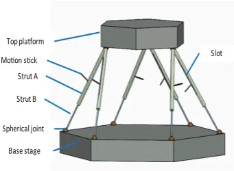
Spherical joint Strut B Top pla!orm
Base stage Strut A
[image:1.595.344.515.162.287.2]Mo"on s"ck Slot
Fig. 1. Design of a 3-6 Hexapod Platform
of measuring the displacement of the top platform by means of the data of the struts lengths. A kinematic modeling is described based on the topology and geometric layout of the design. A forward kinematic solution is analyzed to build an algorithm of two situations for measuring the displacement of the top platform. Discussion and Comparison are proposed for guiding the use of the measurement algorithm.
The rest of the paper is organized as follows. Section II illustrates the design and the topology of the 3-6 hexapod platform. In Section III, we present the kinematic model of the platform. In section IV, the forward kinematics measure-ment algorithm is proposed for this motion sensor design, based on two angle systems. Section V is the case study and discussion of the forward kinematics based measurement algorithm. Section VI is the conclusion of the paper.
II. DESIGN OF A 3-6 STEWART PLATFORM
In this section, we present the design of a platform sensor based on the 3-6 Stewart Platform. The design principle and the topology of the platform are described.
A. Design of a 3-6 Stewart Platform
In order to obtain the displacement in 6DOF, we decide to use a hexapod design. The parallel Stewart Platform design has the advantage of high precision with limited workspace and is widely used in many applications. However, it is not efficient to obtain the solution of forward kinematics. In order to obtain the forward solution, we choose a 3-6 hexapod platform instead 6-6 hexapod platform. The struts are independent in 6-6 hexapod platform while each two struts are connected on the same top points in a 3-6 hexapod platform.
y
x
1
4
3
2
5
[image:2.595.334.515.52.270.2]6
Fig. 2. Schematic Drawing of the Hexapod Platform.
A and strut B, shown in Fig. 1. Strut A is a tube with a long slot. One end of the strut A is installed with a spherical joint, which is connected to the top platform. Strut B is placed into strut A. One end of the strut is also installed with a spherical joint which is connected to the base stage. A motion stick of strut B is extruded from the slot of the strut A. The motion stick is used to attach translational displacement sensor.
B. Topology Analysis
As shown in Fig. 2, we build the global coordinate system on the top center of the top platform at the home position. The base stage is fully constrained in 6DOF. The struts are connected to base stage with six spherical joints. Bottom 6 spherical joints are independent between each other and each has 3DOF of rotation. The top platform is connected to 3 spherical joints. The six struts are connected in parallel to the top platform at the three joints. Each two struts are connected to one joint independently from each other. This means that each strut also has 3DOF at the top spherical joint. This setting can be considered as six independent spherical joints while each two joints geometrically overlap at the same place.
III. KINEMATIC MODEL
In this section, we illustrate the kinematic modeling of the hexapod mechanism. The geometric layout is described and then the kinematic model is derived.
A. Geometric Layout
For convenience, we define the following parameters for describing the geometry of the kinematic model. The length of each strut is denoted as Li, which is defined as the
distance between the centers of the two spherical joints located respectively at the end of the strut Ai and Bi. At
the original position of the hexapod mechanism, we denote the positions of the three center points at the top platform and the six at the base stages byA0
i, and byBi0, respectively. L0i is the original length of the strut. Fig. 3 shows the geometrical relationship of the nine points. The top three points are symmetrically placed at the corners of a triangle. The bottom six points are also symmetrically placed at the corners of a hexagon. The variation of the location of the
a
r
b
r
x y
o
1
k
2
k
i α i β
0 3 B
0 4 B
0 5 B
0 6 B 0
1 B 0 2 B
0 3 A 0 2 A
0 1 A
Fig. 3. Geometric Layout of the Joints of the Top Platform and the Bottom Stages.
bottom six points could be polar symmetrical, such as the example shown in Fig. 2. We denote the distance between the intersecting points of the struts at the bottom stage ask1. For
the top platform, the distance between the intersecting points of the struts isk2. These points on the moving platform and
the stages can be described in the global coordinate frame as
A0
i = [Rz(2π/3)]
ra 0
−t
, i= 1, . . . ,6
B0i = [Rz(π/3)]
rb 0
−H−t
, i= 1, . . . ,6 (1)
where[R(·)]is the 3-by-3 rotation matrix about the z axis.
H denotes the height between the top surface of the bottom stage and the bottom surface of the top platform. t is the thickness of the top platform.ra andrb are the radii of the
strut attachment points (bottom plates in home position)[18], [19]. H is the height of the hexapod mechanism from the bottom stage to the top plane of the platform and it is derived as the unknown by solving equation(A01−B0
1)T(A01−B10)−
L0 1 2
= 0.tis the thickness of the top platform.
B. Kinematic Model
As shown in Fig. 4, line d1 is defined as the shortest
distance between point A1 and vector −−−→
B01B20. Thus, d1 is
perpendicular to −−−→B10B02 and the interaction of them is C1
[17]. As shown in Fig. 5, the vectord⃗1is−−−→C1A1. Go through
C1, we draw a vector ⃗e1, which lies in the plane of base
stage, and is perpendicular to the z axis of the global frame.In geometric math,⃗ei is defined as
⃗
ei=⃗z×⃗ui, i= 1,2,3 (2)
where vector ⃗ui is the normalized vector of
−−−→
B20B 0 1,
−−−→
B40B 0 3,
−−−→
B06B 0
[image:2.595.77.257.52.222.2]1
A
1
c
0 1
B
0 2
B
1
d z
r
1
[image:3.595.86.260.54.164.2]er
Fig. 4. Kinematic Modeling of the 3-6 Hexapod Mechanism.
⃗ u1=
−−−→
B20B10 k1 ⃗
u2= −−−→
B40B30 k1 ⃗
u3= −−−→
B60B50 k1
(3)
where vector−−−→B02B10 and−−−→B20B10 are denoted as
−−−→
B02B 0 1 =B⃗
0 1−B⃗
0
2 (4)
k1= −−−→
B60B50=−−−→B40B03=−−−→B20B10
=
(
⃗ B01−B⃗02
)T( ⃗ B10−B⃗20
) (5)
The lengthdi is defined by the equations
d1=L2Sinϕ1
d2=L4Sinϕ2
d3=L6Sinϕ3
(6)
where ϕi is derived by the k1 and Li. Li denotes the
changed length of the strut when the top platform moves to a new position.
ϕ1=ArcCos (
k2
1+L22−L12
2k1L2
)
ϕ2=ArcCos (
k2
1+L42−L32
2k1L4
)
ϕ3=ArcCos (
k12+L62−L52
2k1L6
) (7)
As shown in Fig. 5, the position of point Ai is derived
by a serial chain of vector C⃗i, and the projection ofd⃗i on ⃗
ei and⃗z.C⃗i is the position vector of pointCi in the global
coordinate.
⃗
Ai=C⃗i+dizSinψ⃗ i+di⃗eiCosψi (8)
where ψi is the angle between d⃗i and ⃗ei. Since the top
platform is a rigid body, the distance between two points is a constant. After we obtain the positions ofAi, we can build
three constraint equations,
E1: −−−→A2A1−k22= 0
E2: −−−→A3A2−k22= 0
E3: −−−→A1A3−k22= 0
(9)
where−−−→A2A1= (A⃗1−A⃗2)T(A⃗1−A⃗2).
1
A
1
L
2
L
0 2
B
0 1
B
1
c
z
r
1
e
r
1
ψ
1
φ
1
d
[image:3.595.382.491.61.201.2]r
Fig. 5. Derivation of the Kinematic Model.
IV. MEASUREMENT ALGORITHM
In this section, we present the measurement algorithm based on the forward kinematics.
A. Forward Kinematics
Regarding the modeling of the parallel mechanisms, it is easier to obtain the inverse kinematic solution than the forward kinematic solution. In the inverse kinematics, the position of the top platform is the input and the output is the lengths of the struts. In the forward kinematics, we try to obtain the position of the top platform in 6DOF given the lengths of the struts.
In the forward kinematics, the output is the displacement of the top platform which is given by a 4 by 4 transformation matrix [T], further defined by a rotation matrix [R] and a vector ⃗v. The transformation matrix [T] is unknown while the lengths are known values in the forward kinematics. However, they are governed by the constraint Eq. (9). After solving Eq. (9) for ψi, we can obtain the positions of the
spherical joints of the top platform at the new position by substitute ψi into Eq. (8). The vector ⃗v is derived by the
center of the three points.
⃗ v=
∑3
iA⃗i
3 (10)
The rotation matrix[R]is
[R] = ([A1A2A3]−[v v v]) [
A01A02A03]−1 (11)
B. Rotation Matrix
As we all know, the rotation matrix can be
obtained by the product of three rotation matrices
[Rx(θx)],[Ry(θy)],[Rz(θz)]. Based on the sequence of
the rotation about the axes, we could obtain 6 combinations.
[R] = [Rx] [Ry] [Rz], [Rx] [Rz] [Ry], [Ry] [Rx] [Rz], [Ry] [Rz] [Rx], [Rz] [Rx] [Ry], [Rz] [Ry] [Rx].
(12)
We can derive the rotational angles θx, θy, θz, in the
forward kinematics given the derived [R] and the sequence of the rotations.
Here, we denote them as θY, θP, θR, respectively. In order
to build the relationship between the rotation matrix and angles, we define the rotation matrix in a general way with 9 elements.
[R] =
aa1121 aa1222 aa1323
a31 a32 a33
(13)
The anglesθY, θP, θR are governed by 3 equations.
a11=Cos(θY) a22=Cos(θP) a33=Cos(θR)
(14)
Due to the property of the rotation matrix, the elements are also governed by 6 constraint equations.
a112+a212+a312= 1
a122+a222+a322= 1
a132+a232+a332= 1
a13=a21a32−a22a31
a23=a31a12−a32a11
a33=a11a22−a12a21
(15)
Given the rotation matrix [R], we can also obtain the angles θY, θP, θR based on Eq. (14) in the forward
kine-matics. However, due to the range of the Cosine function, multiple solutions will be obtained. Thus, we need Eq. (15) to further evaluate the solutions. Multiple solutions are introduced also because of the potential symmetrical layout of the mechanism. It is undetermined if the values of the strut lengths are the only given information. Some more information or assumptions are needed to determine the positions and angles. For example, if the platform is used to continuously measure small displacements, we can apply the minimum energy method to find the unique solution.
C. Motion Measurement of Forward Kinematics
The measurement algorithm of the forward kinematics is illustrated in the flowchart of Fig. 6. Here,δieare the known values. (θex, θey, θez
)
or (θeY, θeP, θRe) and ⃗ve are unknowns. We try to calculate the error of the rotational displacements and the error of the translational displacements⃗µ.
1) Record the measurement dataδe
i of the changed lengths
of the struts.
2) Calculate the total strut lengthLe i.
Lei =L0i +δei (16)
3) Substitute Li as Lei, and build the forward kinematic
model by Eq. (1)-(8). 4) Solve Eq. (9) forψi.
5) CalculateA⃗i by substitute the solutions obtained from
step 4 to Eq. (8).
6) Derive[Re]and⃗vefromA⃗i by Eq. (10) and Eq. (11).
7) Determine the rotational angles of the measurement object:θe
x, θey, θez orθYe, θPe, θeR.
8) Calculateθe
x, θye, θzeby solving Eq. (12).
Or calculateθeY, θeP, θeR by Eq. (14).
9) Obtain the ideal target rotational angles of the object:
θx, θy, θz orθY, θP, θR.
[image:4.595.329.517.52.287.2]Obtain the target translational displacement of the object⃗v.
Fig. 6. Measurement Algorithm of Forward Kinematics.
y
x
x
′
y
′
e
δ
z
θ
Fig. 7. Pure Rotation along z Axis.
10) The errors of the rotational displacement are calculated by
ϵ=θ−θe (17)
whereϵincludesϵx, ϵy, ϵz or ϵY, ϵP, ϵR.
11) The errors of the translational displacement are calcu-lated by
⃗ µ=
µx µy µz
=⃗v−⃗ve (18)
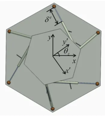
V. CASE STUDY AND DISCUSSION
An example of the pure rotation along the z axis is shown in Fig. 7. Assume that the platform is targeted to purely rotate with an angle θz, our goal is to measure the motion
accuracy of the target object.
[image:4.595.338.513.318.511.2]ϵz=θz−θez (19)
The discussion of the measurement algorithm is shown as following:
1) Forward kinematic algorithm directly shows the errors in 6DOF. The case study shows that it can evaluate the measurement according to the single DOF.
2) In the forward kinematics, we firstly need the measure-ment data and then do a series of calculation based on the data. For example, the target object is programmed to move to a list of ideal target positions. The hexapod sensor follows the object movements and records a list of real data,δe
i. Based on the real data, we derive the
real positions. The target real experimental positions and the ideal target positions can be used to calculate the errors.
3) In the inverse kinematics, we can calculate the theoret-ical solutionδi before the measurement. For example,
a list of the target positions is created. Based on the list, we calculate a list ofδi before the measurement.
During the measurement, we can calculate the error immediately after obtaining the measurement data. This efficient algorithm can also be programmed to a real-time algorithm.
4) Both algorithms require calculation of rotation matrix and translational vector, however the calculation is done in the different steps.
5) According to the requirement of the measurement, we choose the appropriate algorithm.
VI. CONCLUSION
In this paper, we present a design of a 3-6 hexapod platform sensor for measuring the displacements in 6DOF. An analytical model is described based on the geometric layout and kinematic modeling of the mechanism. Based on the forward kinematics, we derive a measurement algorithm according to two angles systems for the hexapod platform sensor. A case study and discussion are proposed for the application of the sensor, and the appropriate choice of the measurement algorithms according to the different situations.
REFERENCES
[1] H.-J. Su, H. Shi, and J. Yu, “A symbolic formulation for analytical compliance analysis and synthesis of flexure mechanisms,” ASME Journal of Mechanical Design, vol. 134, no. 5, p. 051009, 2012. [2] H. Shi and H.-J. Su, “An analytical model for calculating the
workspace of a flexure hexapod nanopositioner,” ASME Journal of Mechanisms and Robotics, vol. 5, no. 4, p. 041009, 2013.
[3] Q. Xu, “New flexure parallel-kinematic micropositioning system with large workspace,”Robotics, IEEE Transactions on, vol. 28, no. 2, pp. 478–491, April 2012.
[4] Y. Li and Q. Xu, “A totally decoupled piezo-driven xyz flexure par-allel micropositioning stage for micro/nanomanipulation,”Automation Science and Engineering, IEEE Transactions on, vol. 8, no. 2, pp. 265–279, April 2011.
[5] H. Shi, X. Duan, and H.-J. Su, “Optimization of the workspace of a MEMS hexapod nanopositioner using an adaptive genetic algorithm,” inRobotics and Automation (ICRA), 2014 IEEE International Confer-ence on, May 2014, pp. 4043–4048, hong kong, May 31-June 7. [6] M. L. Culpepper and G. Anderson, “Design of a low-cost
nano-manipulator which utilizes a monolithic, spatial compliant mecha-nism,”Precision Engineering, vol. 28, no. 4, pp. 469 – 482, 2004. [7] S.-C. Chen and M. L. Culpepper, “Design of a six-axis micro-scale
nanopositionerhexflex,”Precision Engineering, vol. 30, no. 3, pp. 314 – 324, 2006.
[8] N. G. Dagalakis, J. S. Albus, B.-L. Wang, J. Unger, and J. D. Lee, “Stiffness study of a parallel link robot crane for shipbuilding applications,”Journal of Offshore Mechanics and Arctic Engineering, vol. 111, no. 3, pp. 183–193, 1989.
[9] D. Chao, G. Zong, R. Liu, and J. Yu, “A novel kinematic calibration method for a 3DOF flexure-based parallel mechanism,” inProceeding of 2006 IEEE/RSJ International Conference on Intelligent Robots and Systems. IEEE, Oct. 2006, pp. 4660–4665.
[10] K. M. Varadarajan and M. L. Culpepper, “A dual-purpose positioner-fixture for precision six-axis positioning and precision fixturing: Part i. modeling and design,”Precision Engineering, vol. 31, no. 3, pp. 276 – 286, 2007.
[11] H. Shi, H.-J. Su, N. Dagalakis, and J. A. Kramar, “Kinematic modeling and calibration of a flexure based hexapod nanopositioner,”Precision Engineering, vol. 37, no. 1, pp. 117 – 128, 2013.
[12] J.-S. Chen and W.-Y. Hsu, “Design and analysis of a tripod machine tool with an integrated cartesian guiding and metrology mechanism,” Precision Engineering, vol. 28, no. 1, pp. 46 – 57, 2004.
[13] H. Shi and H.-J. Su, “Workspace of a flexure hexapod nanopositioner,” inProceedings of ASME IDETC/CIE, 2012, chicago, Illinois, August 12-15.
[14] H.-J. Su, H. Shi, and J. Yu, “Analytical compliance analysis and syn-thesis of flexure mechanisms,” inProceedings of ASME IDETC/CIE, 2011, washington, DC, August 28-31.
[15] A. Olarra, J. Allen, and D. Axinte, “Experimental evaluation of a special purpose miniature machine tool with parallel kinematics architecture: Free leg hexapod,”Precision Engineering, vol. 38, no. 3, pp. 589 – 604, 2014.
[16] A. Nubiola and I. A. Bonev, “Absolute robot calibration with a single telescoping ballbar,”Precision Engineering, vol. 38, no. 3, pp. 472 – 480, 2014.
[17] P. Nanua, K. Waldron, and V. Murthy, “Direct kinematic solution of a stewart platform,”Robotics and Automation, IEEE Transactions on, vol. 6, no. 4, pp. 438–444, Aug 1990.
[18] H. Shi, H.-J. Su, and N. Dagalakis, “A stiffness model for control and analysis of a MEMS hexapod nanopositioner,”Mechanism and Machine Theory, vol. 80, pp. 246 – 264, 2014.