Abstract—the lack of compatibility between degrees of freedom of various elements is a problem frequently encountered in practice during modeling complex structures. Coupling of membrane and beam elements is an illustrating classical example. The problem is generally treated through an additional rotational degree of freedom. In this respect a new triangular element based on the strain field has been developed with three nodes and three degrees of freedom per node. The triangular presents very good performance and may be used in various practical problems.
Index Terms — Triagular element, drilling rotation, strain model, membrane, plane elasticity.
I. DESCRIPTION OF ELEMENT ' SBTIEIR' The strain displacement relationship in plane elasticity is given
by:
x v y u y v x u xy x x (1)
We first integrate equation (1) with all the strains equal to zero, thus obtaining
3 3 2 3 1 a x a a v y a a u r y r (2)
The assumed strains are 6 :
) ( 9 8 5 7 6 7 5 4 y x a a y a x a a x a y a a xy y x 3)
Manuscript received March 23, 2013, A new strain based triangular element with drilling rotation
Bourezane Messaoud, Civil Engineering and hydraulics Department,
After integrations of equations (3) we obtain:
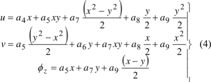
2 2 2 2 2 2 2 9 7 5 2 9 8 7 6 2 2 5 2 9 8 2 2 7 5 4 y x a y a x a x a x a xy a y a x y a v y a y a y x a xy a x a u z (4)
The final displacement field will be obtained by combination of (4) and (2):
2 2 2 2 2 2 2 9 7 5 3 2 9 8 7 6 2 2 5 3 2 2 9 8 2 2 7 5 4 3 1 y x a y a x a a x a x a xy a y a x y a x a a v y a y a y x a xy a x a y a a u z (5)II. DESCRIPTION OF THE PRESENT ELEMENT
The assumed strains are:
)
( 2 2
9 8 7 6 5 4 y x a a x a a y a a xy y x (6)
The final displacement field will be obtained by:
2 2 2 2 3 2 2 9 7 5 3 3 9 8 7 6 2 5 3 2 3 9 8 2 7 5 4 3 1 y x a y a x a a x a x a xy a y a x a x a a v y a y a y a xy a x a y a a u z (7)A New Strain based Triangular Element
with Drilling Rotation
Messaoud. Bourezane
Y
X
V
[image:1.595.316.527.224.306.2]
zi
i UIt was revealed that the unsatisfactory results obtained by using these elements could be due to the unnecessary coupling between the direct strains.
III. NUMERICALEXAMPLES
Numerical results for a variety of problems of plane elasticity are presented to demonstrate the level of accuracy attainable with the present element.
A. Higher order Patch test: Pure bending of a cantilever beam
It is useful to know how behaves a finite element displaying an important geometrical distortion. Sze, Chen and Cheung studied this Problem [9] in order to test the performance and the robustness of elements 07 and 07 *.
Three examples are presented in this section in order to illustrate the interest of the model of strain. The element developed, provided with degrees of freedom of rotation, and is particularly robust and more powerful than the SBTIEIR and classical elements.
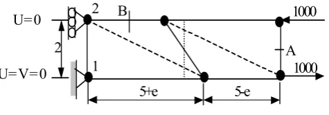
Consider a cantilever beam with rectangular section (L x t x h = 10 x 1 x 2) deformed in pure bending by two nodal forces (P=1000) forming a couple (consisting loading case).
The loading cases (figures 2, 3 and 4) represent the higher patch-test 10.
The cantilever beam is discredited by two rectangular (four triangular) elements of membrane (regular grid) or trapezoidal (distorted grid); various cases of boundary conditions 9 are shown in the figures 2, 3 and 4.
The results obtained with elements SBTIEIR and the present element are compared with the analytical solution given by [IBR 85].
2
1
5+e 5-e
B
A 1000
1000 E = 1500 = 0,25
t = 1,0 U = 0
U = V =Z = 0
2
Fig. 2. Cantilever beam; Data and grids. Rotation Z is free into 2.
2
1
B
1000
5+e
5-e
A
1000
U =
Z= 0
U = V =
Z= 0
2
Fig. 3. Cantilever beam; Data and grids. Rotation Z is fixed into 1, and 2.
1
2 B
5+e 5-e
A 1000 U = 0
U = V = 0 2
[image:2.595.307.545.51.134.2]1000
[image:2.595.314.538.205.363.2]Fig. 4. Cantilever beam; Data and grids. Rotation Z is free into 1, and 2.
TABLE I: DISPLACEMENTS AND STESSES FIG. 2 Present element SBTIEIR
e WA σxB WA σxB
3016 95.82
335 44.77
0
3000 96.37
230 44.51
0.5
3000 96.78
55 9.99
1
3058 97.04
479 46.60
1.5
3058 97.15
464 48.83
2
3048 97.13
419 48.39
2.5
3035 97.02
377 48.84
3
3024 96.87
340 49.01
3.5
3014 96.70
313 49.14
4
3007 96.51
293 49.04
4.5
3000 100 3000 100
Ref. [IBR 93]
TABLE II: DISPLACEMENTS AND STESSES: FIG.3 Present element SBTIEIR
E σ
xB
WA
σxB WA
2976 95.86
326 44.74 0
2990 96.45
215 44.98 0.5
3015 96.91
84 10.42 1
3031 97.14
454 46.51 1.5
3058 97.15
431 47.51 2
3022 97.12
380 48.15 2.5
3010 96.96
332 48.53 3
2999 96.76 292
48.68 3.5
2990 96.52 262
48.65 4
2983 96.29 240
48.48 4.5
3000 100 3000 100
Ref. [IBR 93]
TABLE III: DISPLACEMENTS AND STESSES: FIG. 4 Present element SBTIEIR
e σ
xB WA
σxB WA
3018 96.02
241.40 45.08 0
3030 96.60
230 45.33 0.5
3051 97.04
55 9.84 1
3066 97.30
479 46.88 1.5
3066 97.40
464 47.96 2
3056 97.38
419 48.68 2.5
3044 97.26
377 49.15 3
3032 97.10
340 49.40 3.5
3023 96.90
313 49.47 4
3016 96.70
293 49.40 4.5
3000 100 3000 100
For the case of the regular grid (Table 1; e=0), good results is obtained for the present element contrary to the element SBTIEIR which gives unacceptable results. On the other hand for the case of the distorted grid characterized by the distance "e" (e0), the results of the present element are powerful and comparable to the analytical solution. Element SBTIEIR remains sensitive to the distortions of the grid. The precision is always largely insufficient (Table I and Table II).
In the case of the figure 4b, the robustness of this element via the regular and distorted grid is confirmed. The Tables I and II show stability, the reliability and the good performance of the present element, and whatever the geometrical distortion (only one element on h!). That is explained probably partly by the nature of analytical integration carried out. The distortion has a considerable influence on elements SBTIEIR. (Table I). These results confirm that the element thus developed satisfied good the higher patch (10 and 11).
Table III confirms the good performance and the stability of the present element contrary at element SBTIEIR.
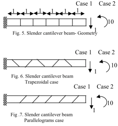
B. Slender cantilever beam of MacNeal
Consider the slender cantilever beam of MacNEAL and Harder 15 with rectangular section (6 x 2 x 1) deformed in pure bending by end moment (M=10) and by a load applied at the free edge (P=1).
The cantilever beam is modeled by six elements of membrane rectangular (figures 5, 6 and 7); trapezoidal (figure 6) and parallelograms (figure 7).
MacNEAL 16 confirms that the trapezoidal shape of the membrane finite elements with four nodes without degrees of freedom of rotation (linear fields) generates locking even if these elements pass the patch-test. This problem has been called as "trapezoidal locking ".
NOTE: This rule does not apply for the strain based element. The results obtained for the present element are compared with those obtained with other known quadrilateral elements (table IV).
TABLE IV: DISPLACEMENT STANDARDISED AT THE FREE END: CASE OF PURE FLEXURE
Element Pure Flexure
Regular Trapezoidal Parallel
Q4 0,093 0,022 0,031
PS5 1,000 0,046 0,726
AQ 0,910 0,817 0,881
MAQ 0,910 0,886 0,890
Q4S MAC 89 - - -
07 1,000 0,998 0,992
Present element 0,989 0,988 0,988 SBTIEIR
SAB 85 0.118 0.004 0.101
Theory of the
beams (0,270) 1,000
TABLE V : DISPLACEMENT STANDARDISED AT THE FREE END: FORCE SHEARING
Element Regular Trapezoidal Parallel Force shearing at the free end
Q4 0,093 0,027 0,034
PS5 0,993 0,052 0,632
AQ 0,904 0,806 0,873
MAQ 0,904 0,872 0,884
Q4S MAC 89 0,993 0,986 0,988
07 0,993 0,988 0,985
Present element 0,964 0,950 0,950 SBTIEIR
SAB 85
0.047 0.0005 0.036
Theory of the beams
1,000 (0,1081)
1 1 1 1 1 1
Case 1 Case 2 Case 1 Case 2
Case 1 Case 2 1
10
1 10
[image:3.595.331.521.86.288.2]1 10 Data : E=107, v=0.3, L=6, t=0.1
Fig. 5. Slender cantilever beam- Geometry
Fig. 6. Slender cantilever beam Trapezoidal case
Through these three cases of grids (figures 5, 6, and 7), we underlined the effectiveness of the present element. The results obtained for elements Q4 and PS5 (table V) show well the problem of trapezoidal locking announced by MacNEAL et al. 16.
In conclusion, we can say that present element is very powerful for this type of problem dominated by bending. It remains stable with the geometrical distortions.
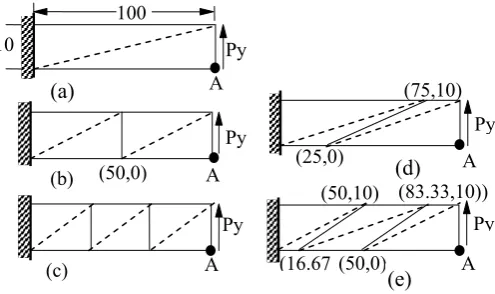
C. Plane flexure of beam cantilever.
A beam cantilever, with uniform cross-section, carries a uniform vertical load (figure 8) calculates the deflection VA at the free end.
Fig 8: Grids regular and distorted
This problem was dealt with by Batoz and Dhatt in their work 11 in order to test the performances of elements CST, LST, Q4, Q4WT 17, 18, Q4PS, 19 and Q8.
Recently Ayad 20 made a similar study to test the reliability of these new elements FRQ and FRT based on the concept " Fibre Planes in Rotation "The results obtained for different grids are presented on table V.
C.1 Comments: grids without distortions (Figures 8a, 8b and 8c)
The results obtained for the present element are powerful and comparable with the robust element Q8.
The present element converges better than CST; it is comparable with element LST in term of a total number of DOF
C.2 Comments: grids with distortions (Figures 8d and 8e)
Very good performance of the present element is confirmed. The corresponding results are more precise than elements FRT, CST, Q8 and are also comparable with element LST in term of the total number of DOF.
TABLE V: BEAM IN PLANE FLEXURE, DISPLACEMENT VA. COMPARISON WITH VARIOUS ELEMENTS
*VA: Vertical displacement in A; IE: Exact integration; PG: Not Gauss point **NDLT: Number total dof; IR: Reduced integration; IA:
Integration analytical
The corresponding results are very close to those obtained with the regular grids. In conclusion, we can say that the present element is very powerful for this type of problem dominated by the flexure. The precision of element SBTIEIR is always largely insufficient.
IV. CONCLUSION
While making it possible to combine various finite elements the ones with the others in the complex structures, the addition of degree of freedom of rotation also makes it possible to improve the precision without increasing the number of nœuds.
Very good results are obtained. The simplicity and the efficiency of this element make it a viable proposition for use in more complex practical engineering problems.
It interesting to explore the combination of present element with elements rich in flexure such as DKT... etc.
REFERENCES
[1] D.J. Allman, A compatible triangular element including vertex rotations for plane elasticity, C.S, Vol. 19, pp. 1-8, 1984.
[2] Bergan P.G. & Felippa C.A., A triangular membrane element with rotational degrees of freedom, CMAME, Vol. 50, pp. 25-69, 1985. [3] Ashwell D.G. and Sabir A.B., A new cylindrical shell finite element
based on simple independent strain functions, IJMS, Vol.14, pp.171-183, 1972.
[4] Sabir A.B., A new class of Finite Elements for plane elasticity problems, CAFEM 7th , Int. Conf. Struct. Mech. in Reactor
Technology, Chicago, 1983.
[5] Sabir A.B. and Sfendji A., Triangular and Rectangular plane elasticity finite elements. Thin-walled Structures 21.pp 225-232 .1995
[6] Sabir A.B., A rectangular and triangular plane elasticity element with drilling degrees of freedom, Chapter 9 in proceeding of the 2nd international conference on variational methods in engineering, Southampton University, Springer-Verlag, Berlin, pp. 17-25, 1985. Fig
FRT Q8 LST CST Present
element
SBTIEIR SAB 85 IR :1
PH IE :3x
3
IE :3PH IE :1P H
IA IA
7 a 2,32 (12) 3,03 (16) (18). 3,00 0,05 (8) 2,8846 (12) 1.42 7 b 2,92 (18) 3,70 (26) 3,70 (30) 0,13 (12) 2,8993 (18) 1.68 7 c 3,07 (24) 3,84 (36) 3,84 (42) 0,25 (16) 2,9289 (24) 1.69 7 d 1,99 (18) 0,64 (26) 3,02 (30) 0,06 (12) 2,9155 (18) 1.42 7 e 2,02 (24) 1,76 (36) 3,09 (42) 0,10 (16) 2,9660 (24) 1.40
A 100
(50,0) A Py
A Py
(25,0)
(75,10)
A Py
(83.33,10)) (50,10)
(50,0)
(16.67 A
Py (b)
(e) (d) (a)
(c)
[image:4.595.43.291.266.413.2][7] Belarbi M.T. et Charif A., Nouvel élément secteur basé sur le modèle de déformation avec rotation dans le plan, Revue Européenne des Eléments Finis, Vol. 7, N° 4, pp. 439-458, Juin 1998.
[8] BELARBI M.T. Développement de nouveau élément fini basé sur le modèle en déformation. Application linéaire et non linéaire. Thèse de Doctorat d’état, Université de Constantine 2000 (ALGERIE)
[9 Sze K.Y., Chen W. and Cheung Y.K., An efficient quadrilateral plane element with drilling degrees of freedom using orthogonal stress modes, C.S., Vol. 42, N° 5, pp. 695-705, 1992.
[10] Taylor R.L., Simo J.C., Zienkiewicz O.C. and Chan A.C., The patch test: A Condition for Assessing Finite Element Convergence, IJNME, Vol. 22, pp. 39-62, 1986.
[11] Batoz J.L. et Dhatt G., Modélisation des structures par éléments finis, Vol. 1 : Solidesélastiques, Eds Hermès, Paris, 1990. [12 Ibrahimbegovic A., Frey F. et Rebora B., Une approche unifiée de la
modélisation des structures complexes : les éléments finis avec degré [13] Timoshenko S. and Goodier J. N., Theory of Elasticity, Mc
Graw-Hill, New York, 1951.
[15] MacNeal R. H. and Harder R. L., A proposed standard set of problems to test finite element accuracy, Finite Element Anal. Des. 1, pp. 3-20, 1985.
[16] MacNeal R. H., A theorem regarding the locking of tapered four-noded membrane elements, IJNME., Vol. 24, pp. 1793-1799, 1987. [17] Wilson E.L., Taylor R., Doherty W.P. & Ghaboussi J.,
Incompatible displacement models, In Fenves et al. (eds), NCMSM, Acadelic Press, New York, pp. 43-57, 1973.
[18] Taylor R., Beresford P.J. & Wilson E.L., Non conforming element for stress analysis, IJNME, Vol. 10, pp. 1211-1219, 1976.
[19] Pian T.H. and Sumihara K., Rational approach for assumed stress finite elements, IJNME, Vol. 20, pp. 1685-1695, 1984.