Programmable H.263-Based Wireless Video
Transceivers for Interference-Limited Environments
Peter Cherriman and Lajos Hanzo,
Senior Member, IEEEAbstract— In order to exploit the nonuniformly distributed
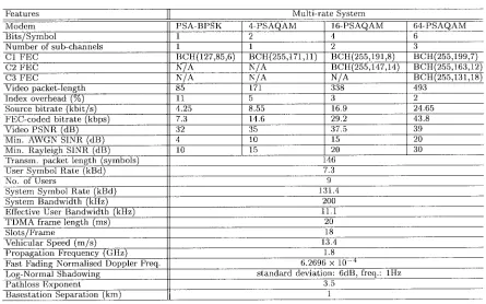
channel capacity over the cell area, the intelligent 7.3-kB pro-grammable videophone transceiver of Table I is proposed, which is capable of exploiting the higher channel capacity of unin-terfered, high-channel-quality cell areas, while supporting more robust, but lower bit-rate operation in more interfered areas. The system employed an enhanced H.263-compatible video codec. Since most existing wireless systems exhibit a constant bit-rate, the video codec’s bit-rate fluctuation was smoothed by a novel adaptive packetization algorithm, which is capable of supporting automatic repeat request (ARQ)-assisted operation in wireless distributive video transmissions, although in the proposed low-latency interactive videophone transceiver, we refrained from using ARQ. Instead, corrupted packets are dropped by both the local and remote decoders in order to prevent error propagation. The minimum required channel signal-to-interference-plus-noise ratio (SINR) was in the range of 8–28 dB for the various transmission scenarios of Table I, while the corresponding video peak-signal-to-noise ratio (PSNR) was in the range of 32–39 dB. The main system features are summarized in Table I.
Index Terms— H.263-based video communications, interactive
wireless video, QAM-based video transmission, video communi-cations in interference-limited environments, video tranceivers.
I. INTRODUCTION
W
HILE video researchers continue to innovate in the field of compression, as evidenced by the excellent special issues edited by Tzou et al. [1] as well as Girod etal. [2], the importance of robustness against channel errors is
becoming a dominant issue for wireless applications. This is evidenced, for example, by the special issue edited by Gharavi
et al. [3]. The video coding community is working toward the
first “wireless-ready” standard video codec, the new Motion Pictures Expert Group scheme known as MPEG4 [4], while the communications community is endeavoring to contrive transceivers supporting the operation of existing standard video codecs, such as the MPEG1, MPEG2, H.261, and H.263 schemes [5], over hostile wireless channels [6]–[8]. Motivated by these worldwide trends, in this contribution, we set out to contrive an H.263-based pilot-symbol-assisted multilevel programmable videophone transceiver [12], which can adapt to time-variant system optimization criteria under a variety of
Manuscript received August 2, 1996; revised May 15, 1997. This work was supported by Motorola ECID, Swindon, U.K., by the European Community, Brussels, Belgium, by the Engineering and Physical Sciences Research Council, Swindon, U.K., and by the Mobile Virtual Center of Excellence, U.K. This paper was recommended by Associate Editor H. Gharavi.
The authors are with the Department of Electronics and Computer Science, University of Southampton, Southampton SO17 1BJ, U.K.
Publisher Item Identifier S 1051-8215(98)03976-7.
propagation conditions. The system’s philosophy is that it can reconfigure itself as a more robust, but less bandwidth-efficient or a more bandwidth-efficient, but less resilient scheme, as suggested by the system parameters summarized in Table I, which will be described during our further discourse.
The effects of cochannel interference are addressed in Sec-tion II. The parameters of the proposed system are described in Section III, while a novel adaptive packetization scheme is introduced in Section IV, which assists in maintaining a near-constant bit rate in any of the modem operational modes as well as creating a regime for reencoding video packets at different bit rates, if it is required by the system’s higher layer functions. The packetization algorithm is capable of supporting automatic repeat request (ARQ)-assisted operation in wireless distributive video transmissions, although in the proposed low-latency interactive videophone transceiver, we refrained from using ARQ. Instead, corrupted packets are dropped by both the local and remote decoders in order to prevent error propagation. The system performance is detailed in Section V, before concluding in Section VI. Let us now commence our discourse on the effects of cochannel interference.
II. COCHANNEL INTERFERENCE
The cochannel interference performance and capacity of various cellular systems were investigated, for example, by Lee and Steele in [10]. Our cochannel interference studies have mainly concentrated on the uplink of hexagonal cells with a reuse factor of 7 and reuse distance of 1 km, employing an omnidirectional antenna at the center of each 400-m-diameter cell. This is a commonly investigated cellular cluster type, where each basestation has six so-called first-tier cochannel interferers. In order to study how the position of the interferers affects the cochannel interference, the following scenarios were investigated.
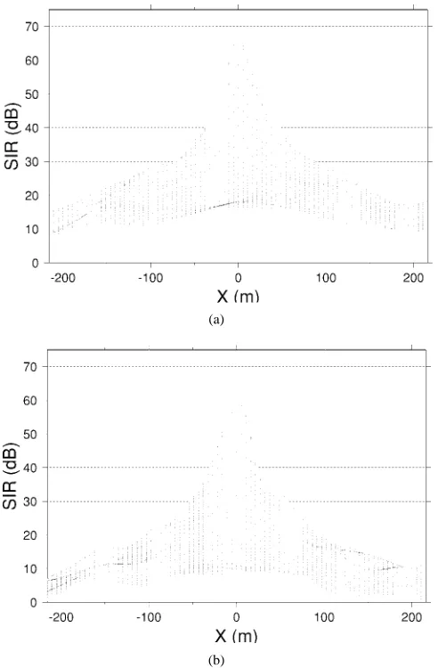
1) The least detrimental, i.e., “best” interferer position, where all of the interferers are placed as far as possible from the interfered BS. This situation is illustrated for the stipulated propagation conditions of Table I in Fig. 1(a) in terms of the signal-to-interference ratio (SIR) versus distance from the BS.
2) Worst case interferer position, where all of the interferers are positioned as close as possible to the interfered BS, which is characterized by Fig. 1(b).
3) Random interferer position, where interferers are allo-cated randomly within their cell, representing the most typical scenario.
(a)
[image:2.612.47.293.57.432.2](b)
Fig. 1. Simulated average SIR (dB) profile of a hexagonal cell, employing a reuse factor of 7, path-loss exponent of 3.5, slow-fading frequency of 1 Hz, standard deviation of 6 dB, 4-QAM modulation, interference from six video users in cochannel cells.
It was found that the SIR difference between the best and worst interferer positions varied, but at the edge of the cell was, on average, about 6 dB, which is also demonstrated by comparing the subfigures of Fig. 1(a). Again, the high-SIR central portion of the cell provides a higher maximum channel capacity, which will be exploited in terms of better video quality by our programmable transceiver of Table I. In case of voice-activity-detection-assisted speech transmissions, the above interference loads are reduced by about 4 dB due to the approximately halved on-air time.
Due to the fast and slow fading of both the signal and in-terference, the instantaneous signal-to-interference-plus-noise ratio (SINR) has a larger variance in interference-limited scenarios. This can be particularly adverse when the uplink signal is highly attenuated by a deep fade and coincidently the interference is boosted by the fading, resulting in a very low instantaneous SINR. This effect is clearly demonstrated by Fig. 2, where the cumulative distribution function (cdf) of the SINR averaged over one time division multiple access (TDMA) frame for our wireless videophone system to be proposed during our forthcoming discussions is portrayed for various amounts of average interference and noise powers.
(a)
[image:2.612.308.557.59.478.2](b)
Fig. 2. Cumulative distribution function of the instantaneous SINR over each TDMA frame due to the worst case single video interferer scenario for various average SNR and SINR values.
Observe in Fig. 2 that, depending on the prevalent average SIR, a substantial fraction of the time the near-instantaneous SINR averaged over a TDMA frame was significantly less than the long-term average SINR. The average SINR profile of the previously used hexagonal cell is characterized in Fig. 3, where (a) is the global three-dimensional (3-D) view, while (b) portrays the corresponding contour plot. As before, the SINR profile shown suggests that an intelligent transceiver can exploit the high channel quality of the cell’s central section, which supports the rationale of this contribution. Having characterized the propagation environment, let us now focus our attention on aspects of the proposed transceiver.
III. SYSTEM PARAMETERS
(a) (b)
Fig. 3. Simulated SINR contours of a hexagonal cell, employing a reuse factor of 7, path-loss exponent of 3.5, slow-fading frequency of 1 Hz, standard deviation of 6 dB, and random 4-QAM video user positions within cell boundaries.
TABLE I
SUMMARY OFSYSTEM FEATURES FOR THERECONFIGURABLEMOBILE RADIOSYSTEM
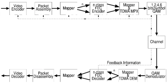
video communications under favorable channel conditions, while invoking more robust, but lower video-quality modes under hostile channel conditions. The feedback control loop of Fig. 4 indicates that transceiver reconfiguration can be invoked on the basis of evaluating the decoded error rate statistics at
the receiver, and the specific design of the reconfiguration algorithm is the subject of our current research.
[image:3.612.77.522.398.676.2]quadrature-Fig. 4. Reconfigurable transceiver schematic.
amplitude-modulation (QAM) modem [12]. Here, we refrain from detailing the BCH coding and QAM issues; the interested reader is referred to [11], [12] for an in-depth discourse. The system can operate, under network control, in one of four modes, corresponding to 1-, 2-, 4-, and 6-bits/symbol modulation schemes. This allows the system to span a wide range of operating conditions in terms of video quality, bit rate, robustness against channel errors, and implementational complexity, while exploiting the higher channel quality of the central region of Fig. 3. For example, the transceiver operates using highly bandwidth-efficient 64-level pilot-symbol-assisted quadrature amplitude modulation (64-PSAQAM) in a benign indoor cordless environment, where high SNR’s and SIR’s prevail. The number of modulation levels is dropped from 64 to 16, when the portable station (PS) is handed over to an outdoor street microcell, and can be further reduced to 4 or 2 in less friendly propagation scenarios. Again, the system parameters are summarized in Table I.
We note that the different QAM modes have a number of different integrity subchannels, where this number ranges from 1 to 3, an issue detailed in [12]. In general these modulation subchannels can provide bit-sensitivity matched protection, however, in the case of the H.263 scheme to be used in our transceiver, all bits are very sensitive to transmission errors, and hence have to be equally well protected. Therefore, we adjusted the error correction power of the various subchannel’s BCH codes in order to equalize the different subchannel integrities, as suggested by the different BCH codecs of Table I. The propagation conditions are also listed in Table I. The baseline H.263 codec algorithm was employed for 10 frames/s, 176 144 pixel so-called quarter common intermediate format (QCIF) videophone sequences without any of the so-called advanced negotiable options, which minimized the system’s complexity and latency, considering that, for example, the advanced predictive motion compensation option relies on the accomplished decoding of surrounding blocks.
An adaptive packetization algorithm to be described during our forthcoming discourse in Section IV was invoked in order to ensure that the H.263 codec generated the closest possible number of bits to the required target rate supported by the currently used transceiver mode. Here, this was achieved by
invoking the specific H.263 quantizer generating the current target source rate facilitated by the instantaneous channel quality, which can span a bit-rate range of 1–6, corresponding to the 1–6 bit/symbol QAM modem modes. In contrast, in [14], a set of 5–11.36 kbit/s, 10 frames/s QCIF proprietary video-phone codecs was proposed, which could dispense with error-sensitive variable-length coding, where a fixed video rate was achieved by classifying the blocks as motion active/passive and coding a fixed proportion of blocks for transmission. This fixed-rate bit allocation resulted in a slightly fluctuating objective video PSNR in comparison to the H.263 scheme, but this was perceptually unobjectionable and amenable to trans-mission over contemporary fixed-rate mobile channels, such as the Pan-American IS-54, IS-95 systems and the Japanese PHS or the Pan-European DECT, CT2 as well as GSM schemes.
Again, irrespective of the transceiver mode facilitated by the current channel quality, as seen in Table I, a constant forward error-correction-coded signaling rate of 7.3 kBd was maintained. When opting for a modulation excess bandwidth of 50% and a system bandwidth of 200 kHz, as in the Pan-European GSM system, the maximum signaling rate becomes 133.33 kBd. At this signaling rate, INT(133.33/7.3) 18 time slots can be created, where INT indicates integer division. Assuming an identical speech signaling rate of 7.3 kBd, nine videophone users can be supported by the proposed scheme in the GSM system’s 200-kHz bandwidth. A range of further system aspects can be inferred from Table I.
[image:4.612.138.462.51.215.2]IV. ADAPTIVE PACKETIZATION
A. Transmission Packet Structure
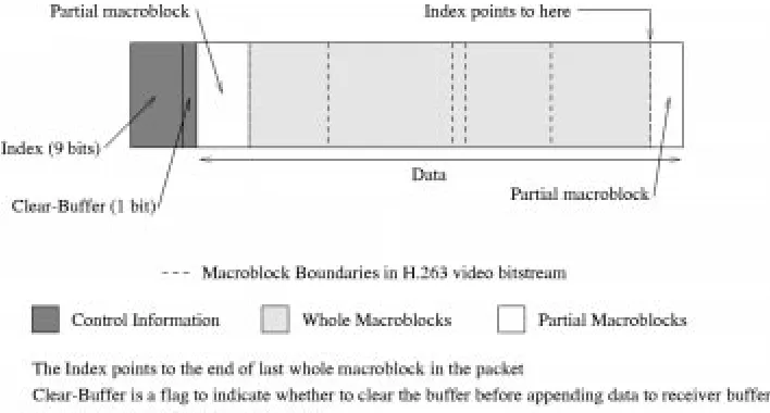
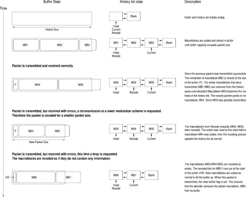
Consider initially the transmission packet format shown in Fig. 5, exhibiting two main constituent segments, the data- and the 10-bit control information. The latter part assists in the “management” of corrupted packets, while the packetization algorithm itself maintains the required target bit rate of the programmable transceiver. Nine bits of the control information are allocated to an index or pointer, which points to the end of the last whole macroblock in the packet, where the packet may contain the bits representing a number of H.263 macroblocks (MB) plus a fraction of the most recently encoded MB. This fractional MB was allocated to the current transmission packet in order not to waste channel capacity. This pointer is used in order to ensure that the decoder only decodes whole macroblocks. The partial macroblock after the indexed point is buffered at the decoder, until the remainder of the partial macroblock is received. The control information segment also contains a 1-bit flag, which is used to inform the decoder, whether the decoder’s received signal buffer containing an already error-freely received partial MB has to be cleared, before appending the current packet. Explicitly, this flag is set by the encoder in order to inform the decoder to drop the already error-freely received partial macroblock from its received signal buffer, when the remainder of the correspond-ing MB’s information was dropped due to packet corruption. Before we can discuss the packetization algorithm and its operating scenarios, we must first consider the mechanism of packet ARQ or dropping in case of corruption.
B. Coding Parameter History List
In order to enable the reencoding of the MB’s for either of the possible error control scenarios, namely, for packet retransmission or dropping, the history or previous values of the unquantized coding parameters have to be stored for every MB in the encoder’s buffer. This was necessary since the encoder has to remember, for example, the unquantized discrete cosine transform (DCT) coefficients, the MB position, the current MB coding mode, etc. until the error-free arrival of this specific MB’s encoded information at the decoder. If, for example, the packet is corrupted during its first trans-mission attempt, it may have to be reencoded using more coarse quantizers in order to be transmitted by a more robust but lower capacity modulation mode, which would not be possible without this coding parameter history list, storing the unquantized quantities. The history of coding parameters was implemented as what we referred to as a bidirectionally linked list, as follows. Each element of the list represents an MB, and contains the unquantized coding parameters. Here, initially, a brief general description is given, the algorithm’s particular manifestation will depend on the specific application scenarios exemplified in Section IV-D. Each new MB is added to the tail of the list, then encoded, and the coded bit stream is appended to the transmission buffer.
The packetization algorithm exemplified in Fig. 6 has three pointers to the above-mentioned linked list. Head points
to the head of the list, Recode to the first macroblock to be reencoded for retransmission, and Current pinpoints the next element/macroblock to encode. Again, the role of these pointers will become more clear with reference to our example of Fig. 6, detailed in Section IV-D, here only a few general comments concerning their employment are offered. For ex-ample, the Recode pointer points to the same macroblock as the Head pointer when the decoder has no partially received MB’s in its buffer. When the decoder stores a partial MB in its buffer, the Recode pointer points to the second MB in the list. This is because the partially transmitted MB, which is at the head of the list, must be either dropped or the remainder of the MB must be transmitted. When a new MB is added to the list, it is placed in the blank list element at the tail of the list, and a new blank list element is created.
When the transmission buffer becomes filled above the defined limit corresponding to a transmission packet, its con-tents up to the limit are transmitted. If the transmission was successful, then the linked list elements corresponding to the fully transmitted macroblocks are removed from the head of the list. The partially transmitted macroblock then becomes the head of the linked list. The Recode and Current pointers point to the blank list element at the end of the list.
If the transmission failed, but a retransmission at a different bit rate is requested, then the codec is instructed to reset its state to what it was, before the MB pinpointed by the Recode pointer was encoded. The remaining MB’s are then reencoded until the buffer becomes filled up to the size of the new transmission packet size. This packet is then transmitted in the usual way.
If a packet was corrupted, but no ARQ was requested, then it must be dropped by both the local and remote decoders in order to prevent error propagation. This delay, low-complexity scenario is preferred in our proposed system, in which case the codec is reset to the state before the MB pinpointed by the Head pointer was encoded, and the MB’s in the history list are then reencoded as if they were empty. When this operation is complete, the encoding of new MB’s continues as usual. However, when the next packet is transmitted, the 1-bit clear buffer flag of Fig. 5 for the forthcoming packet is set in order to clear the receiver’s decoding buffer from the partially transmitted MB that may be in it.
The H.263 coding parameters that are saved in the history list are as follows:
• the unquantized DCT coefficients; • macroblock index;
• buffer size before encoding the macroblock;
• various quantizer identifiers used by the bit-rate control algorithm;
• current macroblock coding mode.
Fig. 5. Structure of a packet generated by the modified H.263 video codec.
the next section on adaptive packetization, requantization may be necessary even without employing ARQ in order to meet the target bit-rate constraint of the current transceiver mode. In the case of packet dropping, as expected, the associated video blocks are simply set to zero. Now that the coding parameter history list and the transmission packet structure have been discussed, the following section describes the packetization algorithm.
C. The Packetization Algorithm
The packetization algorithm had the following objectives. • Pack the H.263 bit stream into the data portion of the
transmission packet seen in Fig. 5, while setting the control information part of the packet, so that the decoder can recover from packet corruption and dropping. • Exploit the packet acknowledgment information in order
to adjust the codec’s bit rate to adapt to time-variant channel conditions.
• Generate programmable size packets so that transceiver reconfiguration relying on different modulation schemes using 1–6 bit/symbol signaling can be implemented. • Ensure that the encoder’s local decoder and the remote
decoder are kept in synchronization after a packet is dropped.
The H.263 codec produces a bit stream maintaining a fixed frame rate for the target bitrate, which is adjusted depending on the channel conditions. The packetizing algorithm operates at the macroblock layer. An example of operating scenarios of the packetization algorithm is given in the next section.
D. Packetization Operation Scenarios
In order to augment our discussions above, in this section, we consider a few operation scenarios of the packetization algorithm, which are portrayed in Fig. 6. At the commence-ment of communications, both the transmission buffer and the history list are empty, as suggested by the figure. When the video encoder starts generating macroblock bits, the transmis-sion buffer is filled by MB1–MB3, where MB3 is seen to
“over-fill” the buffer. The status of the pointers is also reflected in the second column of the figure. Assuming that this packet was transmitted successfully, the “over-spilt” segment of MB3 is transmitted at the beginning of the next packet, as displayed in the third line of Fig. 6. The error-freely received and complete MB1 and MB2 can then be decoded, and their parameters listed above can be removed from the history list. MB3 is now pointed to by the Head pointer, which implies that it constitutes the Head of the coding parameter history list. As mentioned earlier, the pointer Recode holds the position of the first MB to be reencoded for a potential retransmission or dropping. Lastly, the pointer Current is identifying the MB about to be encoded, which is, in this case, MB5. At this stage, the second packet is filled up and ready for transmission, but MB5 “overfills” the packet, and hence the remaining segment is assigned to the forthcoming packet in the fourth line of Fig. 6.
Let us now consider an erroneous transmission scenario, where ARQ is invoked. Assume, furthermore, that the packet containing MB4 and MB5 has to be retransmitted using a more robust, but lower capacity modulation scheme, imposing a smaller packet size portrayed in the fourth line of Fig. 6. Since a substantial part of MB3 has already been error-freely re-ceived, MB3 is not reencoded, but the length of MB4 and MB5 must be reduced. The position of the pointers is unaltered, as suggested by the fourth line of Fig. 6. Hence, the MB’s starting at the position indicated by the pointer Recode are reencoded using the more coarse H.263 quantizers, which generate the required target bit rate. This operation is concerned with MB4 and MB5. Accordingly, the coding parameter history list is reset to its state, before MB4 was originally encoded, since the same unquantized DCT coefficients, MB index, MB coding mode, etc. must be used as during the first encoding operation. The reencoded MB4 and MB5 now “over-fill” the shortened transmission packet constrained by the lower order modulation scheme.
Fig. 6. Example of the packetization algorithm.
number of retransmission attempts has expired. In this case, the packet is dropped in order to prevent error propagation in both the local and remote reconstructed frame buffers. In the H.261 scheme, macroblocks could simply be dropped since each macroblock contained an address. By contrast, in the H.263 scheme, every macroblock has to be transmitted. However, inactive macroblocks are coded using a one bit codeword. Due to the packet drop request, now the MB’s are reencoded as empty MB’s conveying no information. This practice is followed in our scheme in general, i.e., dropped macroblocks are reencoded as empty, requiring 1 bit for each dropped macroblock. These bits are represented by the segment DR at the bottom of Fig. 6. Then the forthcoming MB’s, MB6 and MB7, are encoded as usual, and assigned to the next transmission packet. When this packet is transmitted, the “clear buffer flag” of Fig. 5 is set in order to inform the decoder that the partially received MB3 has to be removed from both the local and remote decoders’ buffer.
The above example has demonstrated all of the possible transmission scenarios, including the actions of the ARQ scheme in the event of packet corruption.
It is worth noting that dropping macroblocks in the way described above, has the effect as some parts of the picture not being updated. However, in most cases, the dropped MB’s will be updated in the next frame. The effect of video packet dropping is not noticeable unless the frame contains a large amount of motion and the packet-dropping probability is very high. These subjective effects can be viewed at various packet dropping rates by displaying the decoded video sequences available on the WWW.1Let us now characterize the system’s video performance.
V. VIDEOSYSTEMPERFORMANCE
A. System Performance Without ARQ
The video system’s performance was evaluated under the propagation conditions of a vehicular speed of 30 mi/h, signaling rate of 7.3 kBd, and propagation frequency of 1.8 GHz, using the set of parameters summarized in Table I.
1Available WWW: http://www-mobile.ecs.soton.ac.uk/peter/robust.h263/
Fig. 7. Average PSNR of decoded video versus frame error rate (FER) for 2-, 4-, 16-, and 64-QAM over both Gaussian and Rayleigh-fading channels. The QCIF resolution Miss America video sequence was used for all transmission modes.
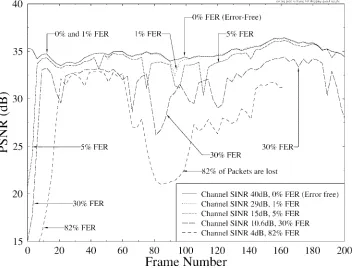
Fig. 8. Decoded video PSNR versus video frame index for transmission over Rayleigh-fading channels for various packet dropping (FER) rates.
At this stage, we have to emphasize that, although the pro-posed adaptive packetization algorithm supports ARQ-assisted operation, for example, for distributive video applications, in our proposed interactive videophone system, we refrained from using ARQ due to its associated latency. Explicitly, we relied on dropping corrupted packets, which was perceptually
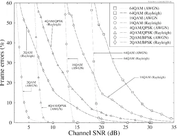
[image:8.612.125.477.372.640.2]Fig. 9. Frame error rate (FER) versus channel SNR (dB) for 2, 4, 16, and 64 QAM over both Gaussian and Rayleigh-fading channels.
degrading motion compensation efficiency. The corresponding PSNR versus SINR curves are portrayed in Figs. 10–12. An alternative solution for future ARQ-based work is to reencode a dropped packet along with the forthcoming one at half the target rate, but transmit them together in the same transmission packet. A further interesting aspect for future research is exploiting the passive speech spurts in voice-activity detector-assisted systems for packet ARQ’s.
We also note that, in the case of wireless local area networks, where typically much shorter frames are used, this latency is acceptable even in interactive videophony [13]. This is particularly true in conjunction with the statistical multiplexing scheme of [13], where the packet acknowledgment bit can be included in the BS’s slot-allocation broadcast message, and a previously corrupted packet can be retransmitted in the same frame as the current one by allocating more slots to the user concerned, at the cost of temporarily disadvantaging other users in terms of the reduced number of slots available to them. Fig. 9 displays the transmission frame error rate (FER) versus channel SNR performance of the system for 2, 4, 16, and 64 QAM over both Gaussian and Rayleigh-fading channels, where a transmission frame was constituted by one of each of the BCH codewords of a given mode of operation seen in Table I. The graphs clearly indicate that extremely robust system performance can be maintained upon invoking the more robust modes of operation when the channel conditions degrade. As expected, the additive white Gaussian noise (AWGN) curves exhibit the typical elbow effect, while the Rayleigh performance curves decay more gracefully with reduced SNR’s. Our perceptual observations and the objective peak SNR (PSNR) results of Fig. 8 suggested that a more robust modem mode has to be invoked when the video packet
error rate reaches about 5%. These performance curves can then be related to the video quality expressed in terms of PSNR using Fig. 7, where all PSNR curves show a gently sloping degradation, as the FER is increased, which is fairly independent for a given FER, whether AWGN or Rayleigh conditions prevailed.
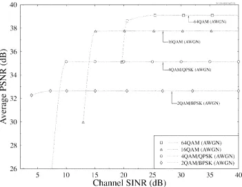
Fig. 8 shows the decoded video peak-signal-to-noise ratio (PSNR) versus the video frame index performance of the system for various video packet-dropping rates in its 4-QAM mode of operation for transmissions over the standard fading channel characterized in Table I. The different packet dropping rates were engendered by using various channel SINR values. Again, in order to prevent excessive video degradations, it is advantageous to reconfigure the system in a more robust mode before the packet-dropping rate increases beyond some 5%. The associated subjective effects are characterized by the corresponding demonstrations that can be viewed on the WWW.2The PSNR versus channel SINR performance of the transceiver is portrayed in Fig. 10 over AWGN channels, while the corresponding Rayleigh-fading channel results are depicted in Fig. 11 without shadow fading and in Fig. 12 with shadow fading exhibiting a standard deviation of 6 dB. The effect of shadowing can be judged when comparing Figs. 11 and 12. Monitoring the FER is a reliable parameter in controlling the modem modes, and it was found advantageous to invoke a more robust modem mode, typically around an FER which was actually reached before the PSNR of a less robust mode dropped below that of the next more robust mode. This implied that a lower unimpaired PSNR was typically preferable to an originally higher, but impaired scenario.
2Available WWW: http://www-mobile.ecs.soton.ac.uk/peter/robust.h263/
Fig. 10. Decoded video PSNR versus channel SNR performance for transmissions over AWGN channels using BPSK, QPSK, 16 QAM, 64 QAM.
Fig. 11. Decoded video PSNR versus channel SNR performance for transmissions over Rayleigh channels using BPSK, QPSK, 16 QAM, 64 QAM.
B. System Performance with ARQ
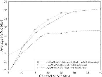
Finally, in order to be able to quantify the expected PSNR performance improvement due to ARQ, in Fig. 13, we com-pared the PSNR versus channel SINR performance of 2 QAM employing packet dropping instead of ARQ, where the video bit rate is about half of the 4 QAM scheme, to that of the 4 QAM system using packet dropping instead of ARQ and
Fig. 12. Decoded video PSNR versus channel SNR performance for transmissions over Rayleigh channels with 6-dB shadow fading using BPSK, QPSK, 16 QAM, 64 QAM.
Fig. 13. Decoded video PSNR versus channel SINR performance for transmissions over Rayleigh channels with 6-dB, 1-Hz shadow fading using 2 QAM with no ARQ in comparison to 4 QAM with one retransmission and without ARQ.
The less than 1-dB PSNR reduction margin is maintained for channel SINR’s in excess of about 15 dB for 2-QAM with packet dropping instead of ARQ, 21 dB for 4 QAM with dropping rather than ARQ, and 24 dB for 4 QAM with one re-transmission. Although the 4-QAM PSNR curves with and without ARQ are always above the 2-QAM curve, for channel
[image:11.612.125.476.365.632.2]posed, which exploited the higher channel capacity of uninter-fered cell areas. The system employed an enhanced H.263-compatible video codec, and it was capable of operating over a wide range of operating conditions, reconfiguring itself according to the prevalent system optimization criteria. The proposed technique has the potential to support interactive videotelephony over existing and future wireless systems using the H.263 video codec. The key system parameters are summarized in Table I. Our future work is targeted at improving the system’s robustness and subjective video qual-ity using so-called turbo-decoded error correction schemes, contriving reconfiguration algorithms, and studying the video performance benefits versus user capacity and latency penalty tradeoffs when using ARQ in high-rate short-frame duration local area networks.
ACKNOWLEDGMENT
This paper is complemented by a demonstration package portraying video sequences at various bit rates, which is down-loadable from http://www-mobile.ecs.soton.ac.uk.
REFERENCES
[1] K. H. Tzou, H. G. Mussmann, and K. Aizawa, Guest Eds., (Special
Issue on Very Low Bit Rate Video Coding), IEEE Trans. Circuits Syst. Video Technol., vol. 4, pp. 213–357, June 1994.
[2] B. Girod et al., Guest Eds., (Special Issue on Image Sequence
Com-pression), IEEE Trans. Image Processing, vol. 3, pp. 465–716, Sept.
1994.
[3] H. Gharavi, H. Yasuda, and T. H. Meng, Guest Eds., (Special Issue
on Wireless Visual Communications), IEEE Trans. Circuits Syst. Video Technol., vol. 6, pp. 133–237, Apr. 1996.
[4] Y.-Q. Zhang, F. Pereira, T. Sikora, and C. Reader, Guest Eds., (Special
Issue on MPEG-4), IEEE Trans. Circuits Syst. Video Technol., vol. 7,
Feb. 1997.
[5] ITU-T, Draft Recommendation H.263: Video Coding for Low Bitrate
Communication, 1996.
[6] M. W. Whybray and W. Ellis, “H.263—Video coding recommendation for PSTN videophone and multimedia,” in IEE Colloq. (Dig.), England, June 1995, pp. 6/1–6/9.
IEEE Press–Pentech, 1994.
[13] J. Brecht and L. Hanzo, “Statistical packet assignment multiple access for variable-rate multimedia sources,” submitted for publication. [14] L. Hanzo and J. Streit, “Adaptive low-rate wireless videophone
sys-tems,” IEEE Trans. Circuits Syst. Video Technol., vol. 6, pp. 305–319, Aug. 1995.
Peter Cherriman received the M.Eng. degree in
information engineering from the University of Southampton, U.K., in 1994.
Since 1994, he has been with the Department of Electronics and Computer Science, University of Southampton, working toward the Ph.D. degree in mobile video networking. Currently, he is working on projects for the Mobile Virtual Centre of Excellence, U.K. His current areas of research include robust video coding, microcellular radio systems, power control, dynamic channel allocation, and multiple access protocols.
Lajos Hanzo (M’91–SM’92) graduated in
elec-tronics in 1976 and received the Ph.D. degree in 1983.