Abstract—Nickel-base superalloys are often used in some of the most challenging applications that require exceptional high-temperature resilience, in terms of the combination of strength, toughness, fatigue and creep resistance, etc. We report an application of a discrete dislocation model to explore the changing hardening performance of a single crystal Ni-base superalloy under cyclic loading as a function of different crystal lattice orientations with respect to the direction of the applied load. We also report the application of a recently developed flexible methodology for measuring (sub)micron scale residual stress utilizing Focused Ion Beam and Digital Image Correlation (FIB-DIC) techniques in the ring-core drilling geometry.
Index Terms—superalloy, discrete dislocation dynamics, residual stress, FIB-DIC.
I. INTRODUCTION
ICKEL-BASED single crystal superalloys allow exquisite control over mechanical properties by means of varying the alloying elements whilst preserving significant ductility characteristic of the face-centred cubic (FCC) structure. The alloys typically display a two-phase microstructure, consisting of cuboidal γ’ precipitates embedded in a γ phase matrix. Increased strength is achieved by the controlled formation of precipitates within single crystal components. Ni-base superalloys are the material of choice used for manufacturing aeroengine turbine blades in which high temperature strength, good fatigue resistance and excellent creep properties are required.
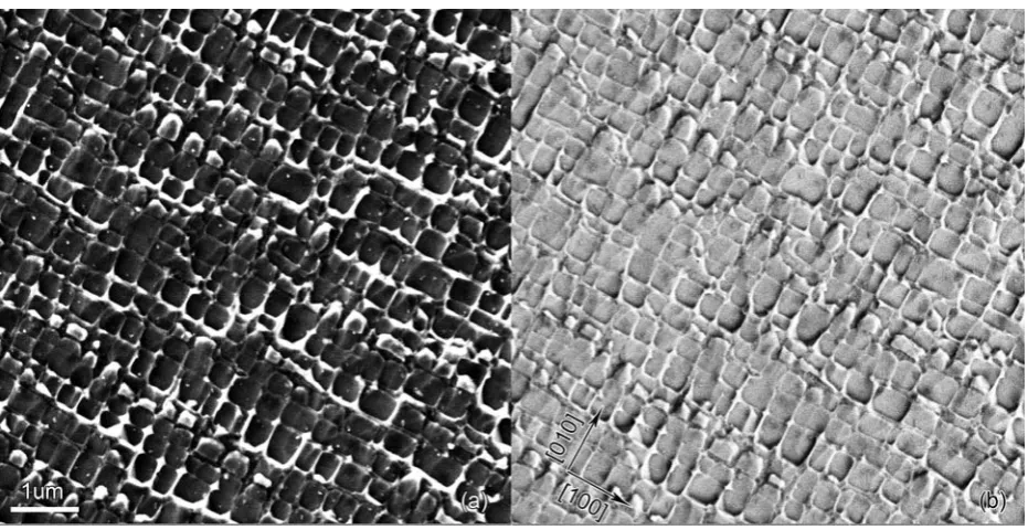
A typical Ni-base single crystal superalloy microstructure is illustrated in Fig 1, where the two-phase structure is initially revealed by light etching and then imaged using secondary electron (SE) and back-scatter electron (BSE) detectors. The γ’ cuboidal inclusions show an average lateral
Manuscript received April 10th, 2014; revised May 1st, 2014. This work
was supported in part by UK EPSRC through grants EP/I020691 “Multi-disciplinary Centre for In-situ Processing Studies (CIPS)”, EP/G004676 “Micromechanical Modelling and Experimentation”, and EP/H003215 “New Dimensions of Engineering Science at Large Facilities”.
Siqi Ying is doctoral student in the Department of Engineering Science, University of Oxford, OX1 3PJ, UK (e-mail: [email protected]).
Tan Sui is doctoral student in the Department of Engineering Science, University of Oxford, OX1 3PJ, UK (e-mail: [email protected]).
Alexander Lunt is doctoral student in the Department of Engineering Science, University of Oxford, OX1 3PJ, UK (e-mail: [email protected]).
Roger C. Reed is Professor of the Department of Engineering Science at the University of Oxford, OX1 3PJ, UK ( email: [email protected]).
*Alexander M. Korsunsky is Professor of the Department of Engineering
Science at the University of Oxford, OX1 3PJ, UK (corresponding author, tel: +44-18652-73043; fax: +44-18652-73010; (e-mail: [email protected]).
dimension of 300-500nm with a volume fraction of about 60-70%, while γ channels in general display a channel width as small as 50nm and less. Although both γ and γ’ phases have FCC-structure, γ’ has an intermetallic L12-ordered crystal structure, with a regular arrangement of Ni atoms occupying face centres of the cubic unit cells formed by alloying element atoms (typically Al, Ti or Ta) [1]. Superior mechanical properties arise from the synergistic interaction between the two phases, with the matrix providing ductility and the precipitates restricting dislocation glide and thus leading to moderating plastic strain and increasing the strength.
The application of Ni-base superalloy in gas turbine blades requires the operation temperature to be as high as about 90% of the melting point [2]. The typical loading experienced by the material is characterised by a flight cycle consisting of the upward ramp in temperature and centrifugal loading, the cruise stage that corresponds to a high temperature dwell at high temperature and tensile stress, and followed by unloading and temperature reduction. In order to make reliable predictions of structural integrity, versatile creep-fatigue modelling is required, taking account of dislocation nucleation, glide, pile-up, climb, and annihilation.
In the present study we focus our attention on the response to cyclic loading, i.e. fatigue. In turbine blade manufacture, the [001]-type crystallographic direction that has the lowest Young’s modulus is commonly oriented along the long turbine blade axis. The manufacturing techniques currently in use are capable controlling to within 5° the primary crystallographic orientation with respect to the blade axis. This is referred to as the angle α defined as the angular difference between the [001] direction and the stacking line [1,3].
From the micro- and nano-structural viewpoint, the way dislocations nucleate, propagate and accumulate in the γ channels, and the way they interact with the γ’ precipitates defines the exceptional mechanical properties of these materials. The visualisation, understanding and quantification of the ultrastructure underpins the modelling of dislocation dynamics, which in turn provides a practical means of predicting the effect of crystal orientation on the fatigue and failure of Ni‐base single crystal superalloy components. In the present study we wish to focus our attention on the effect of the relative misorientation angle between the principal stress direction and the crystal lattice orientation, i.e. the value of the angular parameter α.
Discrete dislocation dynamics (DDD) was introduced as a means of modelling elasto-plastic response of a crystal to mechanical loading in the 1980s, and has become well established since. In the present study, a modified discrete
On the Cyclic Deformation and Residual Stress
in Ni-base Single Crystal Superalloys
Siqi Ying, Tan Sui, Alexander J.G. Lunt, Roger C. Reed and Alexander M. Korsunsky*
dislocation dynamics modelling setup is used that can be referred as 2.5D in terms of its dimensionality: although the model is confined to a single simulation plane, most aspects of the three-dimensional crystal orientation effects are captured. A more detailed description of the model setup is given below.
To enhance the mechanical durability of Ni-base single crystal superalloy components in terms of their resistance to crack initiation due to fatigue and foreign-object damage, studies have been carried out into the use of processes such as shot peening. Other potential candidates include low plasticity burnishing and laser shock peening treatments. In all cases the consequence of processing is embodied in the form of near-surface plastic deformation and the associated residual stresses. Accurate spatially resolved assessment of the residual stress state is therefore of significant applied interest. Whilst methods such as eddy current inspection [4], X-ray diffraction and blind hole drilling have been used for the purpose, these often lack the combination of micron-scale spatial resolution and directional sensitivity that would allow the identification of the components of the stress/strain tensors. A new methodology is applied in the present study for the measurement of residual strain, that can be termed FIB-DIC ring-core drilling, for short [5]. It involves incremental Focused Ion Beam (FIB) milling of an annular marker at the sample surface, coupled with high-resolution in-situ scanning electron microscopy (SEM) imaging and a full field strain relief analysis by Digital Image Correlation (DIC). The associated interpretation procedure is presented and discussed.
[image:2.595.69.535.518.758.2]II. SEM IMAGING
Fig.1 illustrates the microstructure of the Ni-base superalloy RR1000 considered in the present study. The surface of the sample was polished and then lightly etched to provide surface relief that leads to topological contrast in SEM imaging. The difference is apparent in the contrast obtained
by using (a) the SE detector and (b) the BSE detector. The regular, near periodic arrangement of cuboidal inclusions shape and the presence of the crossed network of continuous
channels are the most striking features of the microstructure. They serve as the basis for formulating the DDD model described in the following section.
III. DISCRETE DISLOCATION MODELLING A. Theoretical fundamentals and model setup
Dislocations are extended line defects within crystals that are defined by the Burgers vector b and the line vector ξ. An edge dislocation is the kind for which these two vectors are mutually orthogonal. Edge dislocation glide is the main mechanism of time-independent plastic deformation considered in the dislocation dynamics study of Ni-base superalloy. Although large-scale 3D DDD models have been developed and show good results, they place significant demands on computing power and simulation time. 2D simulations require a lot less effort, but may still provide an excellent means of capturing the fundamental trends of material behaviour. An example of a 2D DDD model is that proposed by Van der Giessen and Needleman [6], in which pairs of edge dislocations are nucleated from randomly distributed sources, and glide along pre-defined slip systems. The speed of dislocation glide is governed by the force arising from applied stress and the influence of other dislocations, and a dislocation mobility function. Several extensions based on Van der Giessen and Needleman’s model have been proposed, and the model used in the present study can be seen as one such extension that aims to take into account faithfully the orientation of crystal slip systems in the FCC crystal structure.
Initial work on the present model has been reported previously [7]. The projection is considered of all available 3D crystal slip systems on the simulation plane, resulting in a set of four distinctly oriented traces of the slip planes. As the crystal orientation varies, the pattern of the slip plane traces
on the simulation plane changes, making it suitable for studying the orientation-dependent mechanical properties of ductile crystals. FCC crystals such as those of Ni-base superalloys have four octahedral slip planes of the {111} type, namely, 111 , 111 , 111 , and 111 . Each close-packed slip plane may accommodate slip along one of the three close-packed slip directions within that plane, e.g. 110 , 101 , and 011 for the 111 plane. Overall this adds up to 12 distinct <110>{111} type slip systems. Given that the simulation plane is characterised by the normal orientation close to 100 , slip directions of the <011> type dominate, resulting in four out of the 12 slip systems being picked for the simulation. A density of Frank-Read sources is selected, and the sources are randomly distributed within the ductile phase. The condition for a pair of edge dislocations to be emitted is the resolved shear stress at the source exceeding the critical value, τnuc. Under the action of the Peach-Koehler force dislocations glide can freely until they reach an obstacle presented by the boundary of a precipitate, or another dislocation. At this stage of modelling the precipitates are treated as impenetrable, with dislocations being stopped at their boundaries.
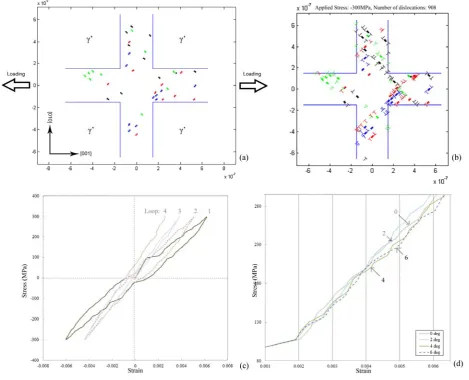
Fig. 2 (a) shows the diagrammatic view of the problem.
The model geometry has been simplified to reflect the characteristic ‘cross channel structure’ of the γ phase. Cyclic loading is applied by means of the remote stress acting along the [001] direction of the unit cell. This is applied to a Representative Volume Element (RVE) illustrated in the figure, with periodic boundary conditions enforced at each edge. This ensures that dislocations escaping the RVE on the right and bottom emerge on the left or from the top, and vice versa. Ten Frank-Read sources were introduced for each slip plane. These are represented by pairs of dots of four different colours.
B. Results
As shown in Fig. 2 (b), as the applied stress increases, dislocation pairs are nucleated and driven in the opposite directions by the action of forces experienced by them, and blocked at precipitate boundaries, leading to the formation of dislocation pile-ups. During unloading some of these dislocations remain pinned, whilst others undergo reverse glide. When two dislocations with opposite Burgers vector signs approach each other travelling along the same slip trace, annihilation takes place if the distance between the dislocations becomes smaller than the critical distance.
In the present work we consider cyclic loading at the
[image:3.595.63.533.359.739.2]temperature of ~700 . The value of Young’s modulus of the γ and γ’ phase is taken to be about 100GPa. The critical resolved shear stress (CRSS) required for the nucleation of a dislocation pair from a Frank-Read source was taken to be 50MPa. No source hardening was assumed i.e. CRSS remained unchanged in the course of deformation. However, the multiplication and interaction of dislocations between themselves and with the obstacles created by the precipitate boundaries resulted in apparent hardening of the system response. Fig. 2 (c) illustrates the cyclic strain hardening observed under load-controlled fully reversed stressing (corresponding to R = -1) along the [001] direction. The amplitude of the cyclic stress applied was set to 300MPa. It is worth noting the variation of flow stress in compression after the first load reversal, which is the manifestation of the Bauschinger effect and in the context of continuum plasticity is referred to as kinematic hardening. This effect can be ascribed to dislocation interaction that causes them to become pinned within the pile-ups in so-called self-locked configurations, meaning that by the fourth cycle, no plastic deformation takes place during load reversal.
The model was used to investigate the difference in plastic deformation response due to difference in the lattice orientation with respect to the load application direction. The monotonic response of the RVE for different α values is shown in Fig. 2(d). Given even the small difference in lattice orientation, the stress-strain curves appear to show some difference. Tentatively it can be reasoned that larger misorientations appear to correspond to less overall hardening at large strains. In order to make firmer statements regarding the effect of crystal orientation on strength, further simulations are required that would allow to capture cyclic loading and creep effects.
C. Discussion and outlook
The 2.5D DDD model presented above appears to show good ability to capture the stress-strain behaviour of a unit cell RVE under cyclic loading, taking into account the effect of lattice orientation. Issues that remain to be addressed concern the criteria for the activation of different slip systems,
and the variation of dislocation source emittance for each slip system. Most importantly, dislocation climb must be considered in the next version of the model in order to capture time-dependent effects and allow the consideration of creep associated with high temperature dwell. Only the combination of suitably calibrated glide and climb dislocation motion will allow the simulation of the temperature and time-dependent creep - low cycle fatigue (LCF) interaction.
IV. RESIDUAL STRESS A. Methodology overview
Residual stresses are the stresses that persist in the material after the deformation causes (i.e. externally applied loads and strains) have been removed. Residual stresses are important in the context of assessing the mechanical performance of engineering materials, since they have been shown to exert significant influence on the fatigue strength of samples and components [8]. To achieve sub-micron resolution in residual stress measurement, a novel method has been developed that combines Focused Ion Beam (FIB) with Digital Image Correlation (DIC) [5,9,10]. In the FIB-DIC ring-core drilling method, surface markers of approximately equi-axed geometry (e.g. circular or cubic) are machined in the area of interest. A reference pattern may be deposited in cases when surface contrast is insufficient for interpretation. Let the marker diameter be denoted by d, and the depth to which it is milled into the surface by h. Straightforward continuum mechanics reasoning, as well as numerical simulation show that once the aspect ratio of the marker, h/d, reaches the value of unity, the central stub or “island”, and in particular its surface, become almost entirely relieved of residual stress. High resolution Scanning Electron Microscopy (SEM) imaging can be used to capture a sequence of images during incremental drilling. This sequence allows strain evaluation from DIC analysis. In this way, the complete in-plane residual stress state can be obtained.
For the purposes of the present study, TESCAN LYRA3 XM was used, the FIB-SEM instrument installed in the
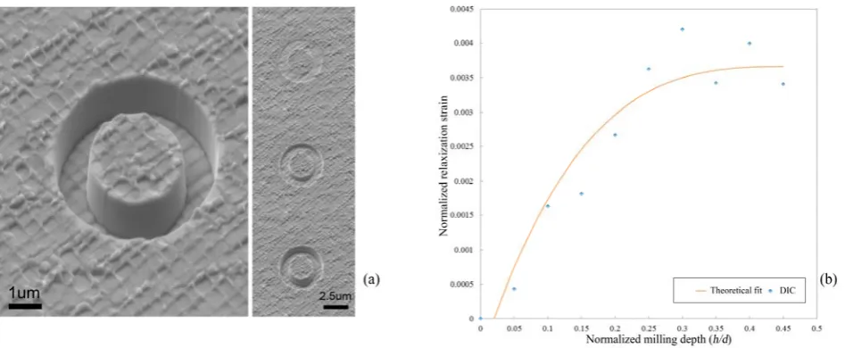
[image:4.595.64.538.552.747.2]Multi-Beam Laboratory for Engineering Microscopy (MBLEM) in the Department of Engineering Science, University of Oxford. Gallium ion source in the FIB column was for FIB milling, and SEM column was used for image acquisition. Fig. 3 (a) shows examples of SEM imaging during FIB milling of the annular trench. The fine setting of the milling process used low ion beam current, ensuring good retention of geometric feature sharpness and maintaining the surface texture of area interest undisturbed. It is interesting to observe the steady progress of the ion beam milling with depth, resulting in the bottom surface of the milled trench retaining the clear two-phase topography contrast inherited from the chemical etching of the sample surface. DIC analysis of the image sequence was conducted using Matlab®-based code developed by Christoph Eberl (2010) [11]. Image shift (rigid body displacement) was allowed for before the displacements of a grid of points on the surface were extracted, and differentiated to obtain strains as displacement gradients.
B. Results and discussion
Fig. 3 (b) presents the plot of relief strain derived from DIC analysis as a function of the normalized milling depth (h/d). Also shown is the fit obtained using the functional expression for strain relief presented in [5,9]. It is apparent that trench milling progressed to the maxium of (h/d) value of 0.5 that was deemed sufficient to obtain a reasonable estimate of the residual strain.
The fitting curve corresponds to eq. (1) [7, 8] given by:
2
2
f (
, ) 1.12
[1
],
1
1
( / 0.42
start)
z
z
z
z
z
h
d
(1)where
is the residual strain, and
startrepresents the zero-depth shift. The fitted value of strain is
=3.27e-3, with
start =0.046m. The positive offset can be readily ascribed to the initial surface roughness due to chemical etching.A degree of mismatch observed between the experimental results (markers) and the theoretical fit curve must be ascribed to noise in the image acquisition and DIC analysis. It is worthwhile to list the various sources of noise in order to progress towards higher precision FIB-DIC procedures. Firstly, image acquisition at different milling steps must be carried out under carefully maintained conditions of constant magnification and, insofar as possible, constant contrast. The latter condition in particular is often difficult to fulfill, due to sample charging (particularly noticeable in non-metallic specimens), a degree of surface damage during milling, and also possible re-deposition of milled material and Ga ions. As a consequence, the surface appearance evolves in the course of trench deepening, and may lead to random error in DIC strain evaluation. Furthermore, the outcome of DIC analysis may have a degree of dependence on the choice of marker location. The development of improved validated procedures for FIB milling and DIC analysis is the central task of the EU FP7 project iSTRESS aimed at the pre-standardisation of FIB-DIC residual stress measurement techniques.
V. CONCLUSION
The results presented in this report pertain to 2.5D discrete dislocation dynamics (DDD) modelling of cyclic elasto-plastic deformation in a Ni-base superalloy. In addition, the results of experimental application of a recently developed semi-destructive FIB-DIC residual stress determination methodology are presented. The utility of the two approaches for the study of Ni-base single crystal superalloys has been shown. The implications of the findings for further development are identified and discussed here.
The initial results of discrete dislocation modelling in application to Ni-base superalloys are overall satisfactory in terms of successful capturing of dislocation glide behaviour and to some degree of the lattice orientation dependent plastic behaviour. Further development of the DDD code is under way, in terms of allowing the simulation of dislocation climb, and in terms of obtaining the prediction of nano-scale residual stress maps following dislocation-mediated plastic deformation.
The trial of FIB-DIC methodology in application to Ni-base superalloy appear to deliver results that can be interpreted well. Further development of this approach can be expected to proceed in the direction of improving spatial resolution and aiming to resolve the two-dimensional residual stress variation at the sample surface that could be compared with the predictions of DDD simulations.
ACKNOWLEDGMENT
AMK acknowledges the support of EPSRC through grants EP/I020691 “Multi-disciplinary Centre for In-situ Processing Studies (CIPS)”, EP/G004676 “Micromechanical Modelling and Experimentation”, and EP/H003215 “New Dimensions of Engineering Science at Large Facilities”. AMK also acknowledges funding received for the MBLEM laboratory at Oxford through EU FP7 project iSTRESS (604646).
REFERENCES
[1] M. Segersäll. "Nickel-Based Single-Crystal Superalloys - the crystal orientation influence on high temperature properties" Linköping Studies in Science and Technology, Licentiate Thesis, 2013,No. 1568.
[2] T. M. Pollock and S. Tin. "Nickel-Based Superalloys for Advanced Turbine Engines: Chemistry, Microstructure and Properties" Journal of Propulsion and Power, 2006, vol.22 no.2 (361-374).
[3] Arakere, N. K. and G. Swanson. "Effect of Crystal Orientation on Fatigue Failure of Single Crystal Nickel Base Turbine Blade Superalloys." Journal of Engineering for Gas Turbines and Power , 2000, 124(1): 161-176.
[4] F. Yu, M. P. Blodgett, P. B. Nagy. "Eddy Current Assessment of Near-Surface Residual Stress in Shot-Peened Inhomogeneous Nickel-Base Superalloys." Journal of Nondestructive Evaluation, 2006,
25(1): 16-27.
[5] A. M. Korsunsky, M. Sebastian, E. Bemporad. "Focused ion beam ring drilling for residual stress evaluation." Materials Letters, 2009, 63(22): 1961-1963.
[6] E. Van der Giessen and A. Needleman. Discrete dislocation plasticity – a simple planar model. Model Simul Mater Sci Eng 1995;3:689. [7] G. Gaucherin, F. Hofmann, J. P. Belnoue, A. M. Korsunsky. "Crystal
plasticity and hardening: A dislocation dynamics study." Procedia Engineering, 2009, 1(1): 241-244.
[8] P.J. WithersH.K.D.H. Bhadeshia. "Residual stress. Part 1 – Measurement techniques." Materials Science and Technology. 2001 [9] A.M. Korsunsky, M. Sebastiani, E. Bemporad, Residual stress
evaluation at the micrometer scale: Analysis of thin coatings by FIB milling and digital image correlation, Surface and Coating Technology,
205(7) 2010.
start
[10] X. Song, et al. "Residual stress measurement in thin films at sub-micron scale using Focused Ion Beam milling and imaging." Thin Solid Films, 2012, 520(6): 2073-2076.
[11] Digital Image Correlation (DIC) code, developed in-house at the Johns Hopkins University, running in Matlab©, free download from http://www.mathworks. com/matlabcentral/fileexchange/12413.
Modified on 1st May, 2014