Abstract—This paper presents a new method of 2DOF H infinity Control for DC Motor. The proposed technique applies the Genetic Algorithms to achieve the specified structure robust control design. The robustness in terms of robust 2DOF control is achieved by the proposed design and the control results are compared with the conventional 2DOF H infinity control. As results indicated, the proposed method is simpler and the order of the proposed controller is lower than that of the conventional robust control technique. The comparison is done by performing the simulation using the transfer function of the real motor system.
Index Terms—2DOF H infinity Control, DC motor system, genetic algorithm
I. INTRODUCTION
oth 2DOF control and robust control can be incorporated to design a robust controller to achieve both time and frequency domain specifications. The technique, called 2 DOF H infinity control is widely used to design the robust control with the time domain specification. However, similar to the robust control techniques, the structure of the resulting controller is normally complicated with high order. In this paper, we propose the design control technique using 2DOF H infinity control and Genetic Algorithms to the DC motor speed control. Many researchers proposed the control techniques for speed control of the motor. Hwu and Liaw [1] studied the speed control of the switch reluctance motor. In their paper, they found that the dynamic system can be approximated but hardly to be accomplished. Lee and Schmidt [2] applied the control method for controlling an uncertainty system and an external disturbance which was examined in the high sensitive system called “seeker scan loop system”. Additionally, they summarized that the 2DOF control is better than the 1DOF control.
Knittel et al [3] presented that the 2DOF H infinity Control can hold the tension control which is disturbed by the adding load torque. Owing to torque load increased, a spool drive was vibrating while operating. The 2DOF H infinity control is able to reduce the vibration in this problem. Harnefors et al [4] adopted the 2DOF H infinity Control for controlling a permanent magnet servo motor which was driven by field oriented control. The results in this paper
Manuscript received January 16, 2014. This work was funded by Cal-Comp Eletronics (Thailand) Public Company Limited and DSTAR, KMITL. This work was also supported by the King Mongkut's Institute of Technology Ladkrabang Research Fund.
Somyot is also with the Faculty of Engineering, King Mongkut's Institute of Technology Ladkrabang, Bangkok, 10520. E-mail :
[email protected] Natchanon and Somyot are with College of Data Storage Innovation, King Mongkut's Institute of Technology Ladkrabang, Bangkok 10520, Thailand. Email: [email protected]
showed that the 2DOF H infinity control can not only decrease the un-modeled dynamics, but also better perform the response than that of the 1DOF H infinity control.
The outline of the article is as follows. Section II consists of the theory of 2DOF H infinity control, the output error system identification, and the new technique of 2DOF H infinity Control for DC Motor using Genetic Algorithms. Section III presents the design of the proposed controller using the 2DOF H infinity Control for DC Motor using Genetic Algorithm. Simulation results are shown and discussed in this section. Finally, the last section concludes the research work and illustrate the discussion.
II. 2DOFHINFINITY CONTROL,SYSTEM IDENTIFICATION AND THE PROPOSED TECHNIQUE
A. System Identification
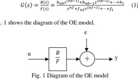
Standard system identification can be performed to determine the parameters of the dynamic model from the measured data in any systems. The measured data derived from the input and output system are used to the identification process. In this paper, the OE (Output Error) method [5] is selected as the linear model of DC motor.
Bringing the measured data and the number of poles (nf) with zero plus one (nb) of system and delay(nk), the black box model identification process can be performed. The results of this process are the model parameters, i.e. f1 ,f2 ,…, fnf and b1
,b2 ,…,bnb. The transfer function of the system is as the following equation.
[image:1.595.317.547.524.658.2]( ) ( ) ( ) ( ) ( ) ( ) (1)
Fig. 1 shows the diagram of the OE model.
Fig. 1 Diagram of the OE model
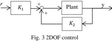
B.2DOF H infinity control
2DOF H infinity control is a method which is able to specify the time domain specification into the H infinity robust control. Normally, H infinity control specifies the specifications in the frequency domain. The 2DOF H infinity control consists of a feed-forward pre-filter controller, K1, and a feedback controller, K2. K1 is used for controlling the
response of time domain of the closed loop system; in addition, K2 is designed for achieving the robust performance
and disturbed reduction of the entire system. The 2DOF H
2DOF H infinity Control for DC Motor
Using Genetic Algorithms
Natchanon Chitsangaand Somyot Kaitwanidvilai
B
+
e
y 𝐵
infinity control uses only one weighting function which is the pre-compensator weight function, W1 to specify the loop shape. In addition, the reference model, Tref is applied to establish the time domain specification. Considering the shaped system (Gs) which can be formulated as co-prime factors [6] which consists of the nominator factor: Ns and the
denominator factor: Ms. Fig. 2 demonstrates the uncertainty model of the system and robust control synthesized systems.
[image:2.595.34.295.151.261.2]
Fig. 2 uncertainty system of co-prime factors When Tref is used for referring the model of the time domain specification.
ρ is a constant which is designed to monitor the well performance of the control system. Loop shaping system can be described in the following equation:
Gs=GW1=Ms -1
Ns (2)
Equation (2) combines the uncertainty into the shaped system.
G∆=(Ns+∆Ns)(Ms+∆Ms)-1 (3)
G∆ is uncertain system.
∆N is uncertain transfer function of the nominator.
∆Ms is the uncertain transfer function of the denominator.
|∆Ns, ∆Ms|∞ ≤ ε (4)
ε is stability margin.
The followings are the steps of the conventional design procedure of the 2 DOF H infinity control.
Step 1 Pre-compensator weight function (W1) is designed
to perform an open loop shaping
Step 2 Reference model (Tref) is designed to refer the time
domain specification of the closed loop system, and to use to select the performance and efficiency of time and frequency domains. has ranged from 0 to 1. If the designer selects , the 2DOF H infinity control becomes the 1 DOF H infinity control.
Step 3 εopt is determined by solving the following equation (5).
|( ) | (5)
Step 4 After step 3, the K1 and K2 are synthesized [7] by
solving the following inequation.
‖ ‖
‖[
( ) ( ) ( ) ( )
[( )
] ( )
]‖ (6)
Step 5 is synthesized by:
[ ( ( ) ( )) ( ) ( )]
( ) (7)
By Wo = 1
Step 6 K1and K2 is tested to ensure the performance of the designed system.
The resulting controller obtained from the above mentioned procedure has high order. If the order of the controller is high, it is difficult to be implemented in real system. To overcome this problem, in the proposed technique, the design of the structure of the controllers K1
and K2 is firstly selected and then the genetic algorithms are
adopted to compute the control parameters of K1 and K2 to achieve the maximum stability margin in (6). Generally, the controller is shown in Fig. 3 for real implementation.
[image:2.595.332.526.320.391.2]
Fig. 3 2DOF control
To summarize the proposed design, the following steps of the proposed technique are described.
Step 1Tref and W1 are selected to achieve both desired loop shape and time domain response. Also, the structures of the controllers K1 and K2 are selected. In this paper, we selected the structures as:
(8)
(9)
Step 2 Genetic algorithm is applied for determining the parameters in K1 and K2 so that the maximum stability margin can be achieved.
‖ ‖
‖[
( ) ( ) ( ) ( )
[( )
] ( )
]‖ (10)
By ( )
Step 3 System performance of the proposed controller is tested.
III. DC MOTOR SYSTEM AND SYSTEM IDENTIFICATION
The DC motor system is designed to create the single axis driving with DC motor. The lead screw changes from the radial motion to linear motion. The angular velocity is measured by the encoder joined at the end of the lead screw. DC motor is driven by H-bridge circuit, and PWM signal is
+ +
+
+
+ +
_
_
Plant +
+
made from a microcontroller, “ARM Cortex-M4 processor” to transfer the data for feedback control.
Fig. 4 Diagram of DC motor system
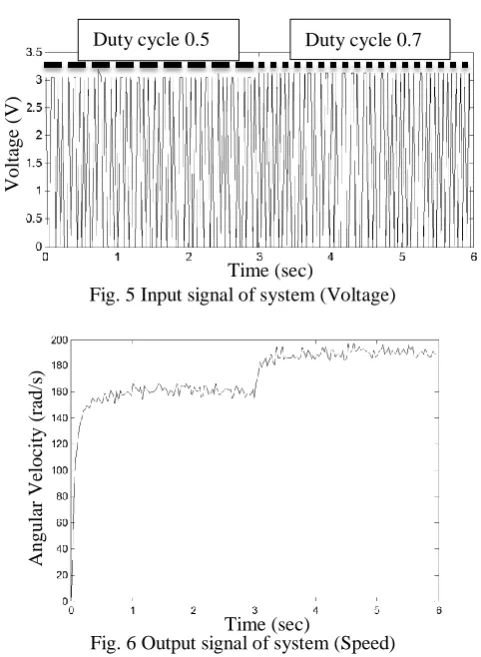
[image:3.595.47.288.279.608.2]The system identification technique was performed to determine the parameters of the dynamic model of DC motor from the measured data. The measured data derived from the input duty cycle shown in Fig. 5, and the speed output shown in Fig. 6. OE (Output Error) method is used for modeling the Linear model of DC motor. This model is created by selecting the identification parameter as nb = 2 , nf = 2 , nk = 1.
Fig. 5 Input signal of system (Voltage)
[image:3.595.312.549.467.639.2]Fig. 6 Output signal of system (Speed) TABLE I. Transfer function derived from system
identification
Duty cycle(%) Transfer function
50-70 B(s) = 8.92103s + 6.152109 F(s) = s2+ 7.106107 s+ 4.746108
60-80 B(s) = 9.15103s + 5.291109 F(s) = s2 + 4.519107 s + 3.293108
IV. EXPERIMENTAL AND SIMULATION RESULTS
This experimental setup adopted in this paper for the system identification is shown in Fig. 4. When applying the proper signal to the system, the measured data needed for the identification can be achieved. Then the identified model was used to the controller design. The identified plants are
shown in TABLE I. The designed plant is the plant at the operating point (duty 50%-70%) and the other plant with duty cycle 60-80% is used to verify the robustness when the plant is changed. The conventional H infinity 2DOF control and the 2DOF H infinity control using genetic algorithm are tested in the system by applying the step response. The performance and robustness in terms of the rise time, overshoot, settling time, bandwidth, and stability margin of the proposed algorithm are investigated in comparison with the conventional control.
In the conventional technique, the weight and reference model were selected as:
(11)
(12)
The selected W1 results in the optimal stability margin εopt > 0.25 and the Tref results in the satisfied settling time. Then, the K1 and K2 were synthesized using the conventional technique as the filters with 4th order.
( ) (13) ( ) (14)
The designed controller by the proposed technique using genetic algorithms was evaluated. The structures of controllers in (8) and (9) were selected. After running the GA for 95 generations, the optimal control parameters,
Kf=1000.9, Kp= 31.0035, Ki= 1694.2, and Kd = 0.492 were
obtained for K1 and K2.
Fig. 7 Stability margin versus generations obtained from the genetic algorithms
The equations (11), (13), and (14) are the weight function and the conventional 2DOF robust controller. As comparison with the proposed controller evolved by GA, the order of the proposed controller is low which is easy to be implemented in practical system.
Duty cycle 0.5 Duty cycle 0.7 Micro controller DC motor
Lead screw Encoder
Duty 50-70
Duty
cyc
le
0.
5
V
olt
age
(
V
)
Duty cycle 0.7 Time (sec)
Duty cycle 0.7 Time (sec)
Duty cycle 0.7
Generation
A
ngular
V
elocity
(r
ad/s
)
A
ngular
V
elocity
(r
ad/s
)
S
tabili
ty
mar
gin
S
tabili
ty
mar
Fig. 8 Step response of the closed loop system from various controllers
Fig. 9 Bode diagrams of the closed loop system from various controllers
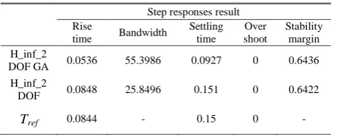
The time domain performance of various controllers is compared as shown in TABLE II.
TABLE II. The comparison of the DC motor control system with various controllers.
Step responses result Rise
time Bandwidth
Settling time Over shoot Stability margin H_inf_2
DOF GA 0.0536 55.3986 0.0927 0 0.6436 H_inf_2
DOF 0.0848 25.8496 0.151 0 0.6422
Tref 0.0844 - 0.15 0 -
[image:4.595.61.288.254.439.2]The result of simulation shows that the identified transfer functions of Output Error system identification are moderate because the studied system is nonlinear system, but the Output Error system model is suitable for the linear system. The step responses of the proposed controller and the H infinity 2DOF control are investigated in the simulation results. As seen in the results in Figs. 8 and 9, the rise time and settling time of the proposed controller is less than the H infinity 2DOF control and the bandwidth of the proposed controller is near the H infinity 2DOF control. In addition, the stability and performance of the proposed controller is similar to the H infinity 2DOF control while the order of the proposed controller is much lower than that of the conventional technique.
Fig. 10 The robustness of the system is tested by the step response in other operating points.
Simulation results shown in Fig. 10 of the changing plants from the designed plant (duty 50%-70%) and the other plant (duty 60%-80%) of the proposed controller shows that the proposed system is robust. The response is similar to the original design even the plant is changed.
V. CONCLUSIONS
This paper proposes the new technique of H infinity 2DOF control using genetic algorithm which is used to search the parameters of controller in fixed structure fashion. The performance of the proposed controller is nearly the same as the conventional H infinity 2DOF control achieved by the synthesis of mathematics. However, the conventional robust 2DOF control is hardly to be used in the practical system because K1 and K2 are normally high order controller. In contrary, the order of the proposed controller is lower, and the proposed system still retains the good performance and robustness. The stability margin verifies the effectiveness of the proposed algorithm. As seen in frequency domain plots and time domain responses, the proposed technique is a promising technique which can be applied to the DC motor system.
ACKNOWLEDGMENTS
This work was funded by Cal-Comp Eletronics (Thailand) Public Company Limited and DSTAR, KMITL. This work was also supported by the King Mongkut’s Institute of Technology Ladkrabang Research Fund.
REFERENCES
[1] K. I. Hwu and C.M. Liaw, “Robust quantitative speed control of a switched reluctance motor drive,” IEE Proc.-Elec. Power Appl.. Vol 148, No. 4, July 2001, pp. 345-353.
[2] H.-P.Lee and D.K.Schmidt, “Robust two-degree-of-freedom control of a seeker scan loop system,” IEE Proc.-Control Theon Appl., Vol. 149, No. 2, March 2002, pp. 149-156.
[3] Dominique Knittel, Edouard Laroche, Daniel Gigan, and Hakan Koç, “Tension Control for Winding Systems With Two-Degrees-of-Freedom H∞ Controllers,” IEEE TRANSACTIONS ON INDUSTRY
APPLICATIONS, VOL. 39, NO. 1, JANUARY/FEBRUARY 2003, pp. 113-120.
[4] Lennart Harnefors, Seppo E. Saarakkala, and Marko Hinkkanen, “Speed Control of Electrical Drives Using Classical Control Methods,” IEEE TRANSACTIONS ON INDUSTRY APPLICATIONS, VOL. 49, NO. 2, MARCH/APRIL 2013, pp. 889-898.
[5] Ljung, L. System Identification: Theory for the User. 2nd edition. New Jersey: Prentice-Hall; 1999.
Step Response Time (sec) A m p lit u d e
0 0.05 0.1 0.15 0.2 0.25 0.3
0 0.2 0.4 0.6 0.8 1 H_inf_2DOF Tref Proposed_controller Bode Diagram
Frequency (rad/sec)
100 102 104 106 108 1010
-180 -135 -90 -45 0 P h a s e ( d e g ) -250 -200 -150 -100 -50 0 M a g n itu d e ( d B ) H_inf_2DOF Tref Proposed_controllers Step Response Time (seconds) A m p lit u d e
0 0.02 0.04 0.06 0.08 0.1 0.12
0 0.1 0.2 0.3 0.4 0.5 0.6 0.7 0.8 0.9 1 Duty_50_70 Duty_60_80 M agnit ude ( dB ) M agnit ude ( dB ) P ha se ( de g ) P ha se ( de g ) Ampli tude Ampli tude Ampli tude Ampli tude
Time (sec) Time (sec)
Step Response Step Response Frequency (rad/sec) Bode Diagram ꜛ ꜜ H_inf 2DOF
ꜛ Tref
Proposed_controller ꜛ Proposed_controller ꜛ H_inf 2DOF Tref ꜜ ꜛ Duty_50_70
Duty_60_80 ꜛ
ꜜ
Tref
ꜜ
H_inf 2DOF
[image:4.595.41.286.518.616.2][6] McFarlane Duncan, Glover Keith. “A loop shaping design procedure using H∞ synthesis.” IEEE Transactions on automatic control. vol. 37,
no. 6, June 1992. pp. 759-769.