1 of 10
Three-dimensional Modelling of the Interaction Between Buildings and Tunnelling Operations A.G. Bloodworth, Southampton University, formerly Oxford University and Brown and Root Ltd
G.T. Houlsby, Oxford University H.J. Burd, Oxford University
C.E. Augarde, Durham University, formerly Oxford University
Keywords: Tunnels, Masonry Structures, Finite Elements, Settlements
Conference theme: Effects of building stiffness, different configurations and time
ABSTRACT: An extensive programme of research has been carried out at Oxford University on finite element analysis of the interaction between masonry buildings and ground movements induced by tunnelling. The focus has been on the development of a predictive tool for assessing the probable damage to buildings. This paper presents a brief summary of the work, with reference to other more detailed papers. The method is illustrated with reference to the case of the Ramsgate harbour approach tunnel, in which a large diameter tunnel in chalk was excavated at very low cover directly beneath a row of cottages. Both field measurements and analyses reveal that in this case the building responds flexibly, following rather closely the greenfield settlements, which were small. The slight damage to the buildings was also correctly modelled.
1. Introduction
An assessment of potential damage to buildings due to shallow tunnelling operations is important when the buildings are of masonry, as small differential settlements may lead to unsightly cracking. Current assessment methods are generally based on a two-stage process. First the greenfield ground settlements are imposed on a structural model of the building to obtain an assessment of the expected damage (e.g Burland and Wroth, 1974). If the building fails this assessment, more detailed analyses are required, but the literature gives little guidance on how this may best be achieved.
Greenfield settlements are usually approximated empirically by a Gaussian curve transverse to the tunnel axis, and by a cumulative probability curve in the tunnelling direction. There is relatively little published data on the more complex settlements that result from interaction with buildings in urban areas. The data that do exist suggest that the presence of surface buildings significantly modifies the settlement profiles from the greenfield.
To assess the extent of likely damage to a masonry building, it is usually assumed that the damage due to cracking is related to the magnitude of the tensile strains developed within the structure. Individual facades of the building may be modelled as elastic deep beams (Burland and Wroth, 1974) on to which the tunnel-induced settlements are imposed. The effect of horizontal movements at the ground surface may also be included (Boscardin and Cording, 1989). Methods based on the assumption of elastic structural behaviour are convenient, but a masonry building is unlikely to behave elastically, particular once significant cracking occurs.
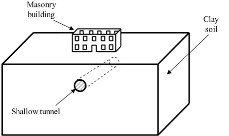
Masonry building
Shallow tunnel
Clay soil
Figure 1: Idealisation of tunnelling under a building in three dimensions
procedures to assess settlement-induced damage to buildings. Details of the project, including the application of the technique to an example problem, are given in Burd et al (2000).
2. Three-Dimensional Finite Element modelling
[image:2.595.70.303.145.283.2]The principle of the model adopted is illustrated in Figure 1. The building, the ground and the tunnelling processes are combined in a single three-dimensional numerical model. The analyses are carried out using the finite element program OXFEM, developed at Oxford University. Details of the relevant finite element formulations are given by Burd et al (1994), Augarde et al (1995), Augarde (1997), Liu (1997) and Augarde et al (1998).
The facades of the structure are modelled by plane stress elements. The roof, floors and internal partitions are not included, although internal load-bearing structural walls are included when necessary. The facades are connected together and to the ground using tie elements (Liu, 1997; Houlsby et al, 2000). Foundation details may be modelled if necessary, but are often neglected if the building is on strip footings.
Ten-noded tetrahedral solid elements model the ground, with a free mesh that enables the density to be increased near the tunnel and building. The ground contains a zone of elements defining the tunnel, and these are removed during the analysis to simulate excavation. This may be carried out incrementally to model the response as tunnel construction progresses: this cannot be done in two-dimensional analysis. The tunnel may be unlined, or lined with shell elements, which enable the ground loss due to tunnelling to be controlled and modelled.
The constitutive model for the ground is a multi-surface plasticity model (Houlsby, 1999). This models the undrained behaviour of stiff clay, including the gradual change in behaviour from elastic to perfectly plastic and the reduction of stiffness over a small strain range. The masonry facades are modelled with a „no tension‟ model, in which the material has a low tensile strength and infinite compressive strength. If a principal strain becomes tensile during the analysis, a crack is formed. The tensile
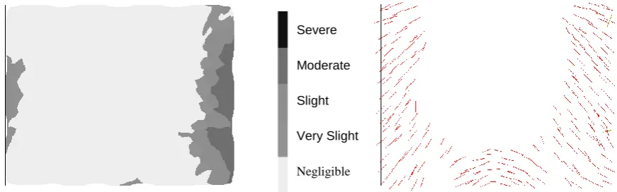
strain normal to the crack (the „crack strain‟) is used as a measure of the intensity of cracking, which in turn indicates the severity of damage to the masonry. The categories of damage used are those proposed by Boscardin and Cording (1989) (see Table 1).
3. Ramsgate Harbour Approach Tunnel Case History
The 2.2km Ramsgate Harbour Approach Road was constructed in 18 months from April 1998. The purpose is to provide improved access to the Port of Ramsgate from the west. The alignment starts at a roundabout on the London road, descending towards the south in a cutting. It then passes through a single bore 800m long, 11m diameter (110m2 cross-sectional area) tunnel through chalk, emerging on the foreshore close to the port. The
Maximum principal tensile strain (%)
Expected severity of damage
0 - 0.05 Negligible
0.05 - 0.15 Slight
0.15 - 0.3 Moderate
> 0.3 Severe
3 of 10 10m
Tunnel Invert Tunnel Crown
Cottages
Brickearth
Weathered Chalk
Competent Chalk
Riv er Grav els
[image:3.595.78.316.218.395.2]Direction of Drive
Figure 2: Section through cottages on axis of tunnel
tunnel was constructed using the Perforex pre-vaulting method (Morgan, 1999), the first use of this French-developed method in the UK.
The tunnel passed under a terrace of cottages near the beginning of the bore, with a minimum of 6m cover. The cottages and the area around them were the subject of detailed monitoring. Measurement of in-tunnel deformations and movements around the tunnel by inclinometers, extensometers and precise levelling was carried out by the site staff. Instrumentation and monitoring of the cottages was carried out by the first author.
Most of the tunnel drive is in competent Upper Chalk, with a typical CIRIA grade of A2. At the cottages however, the Chalk is weathered to grade Dm in places and the thickness of the overlying surface layers become significant (Fig. 2). The tunnel invert remains within chalk that is structured and relatively unweathered, but still rather weak. The upper part of the bore is in weathered to highly weathered chalk. Overlying this is a layer of 2m - 3m of red brickearth, a firm to stiff silty clay. At the location of the cottages, a buried valley crosses the alignment, decreasing the chalk cover over the crown, and increasing the penetration of weathering.
3.1 Tunnel construction
The tunnel boring was by a pre-vaulting technique (Crow and Newman, 1999). A 5m long chainsaw is used to cut a 200mm deep, arched slot around the sides and crown of the bore, which is filled with sprayed concrete to form a prevault, which becomes the primary lining, ahead of the face. Once the prevault concrete has cured sufficiently, the tunnel face is advanced by the use of standard excavation equipment, and an invert slab constructed up to the face. The machine then advances and the cycle repeats. The face is further supported by drilled and grouted sacrificial glass fibre reinforcement. The length of
advance per cycle was between 2.5m and 4.5m, and advance rate was from 12m to over 20m per week, slower in the vicinity of the cottages.
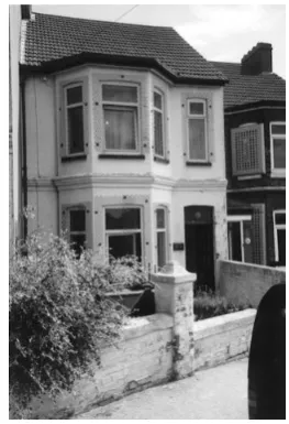
3.2 Buildings
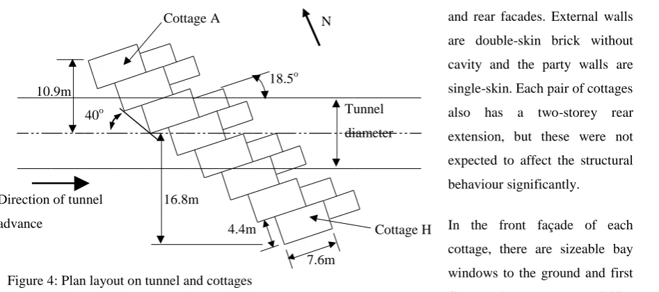
The cottages consist of a terrace of eight similar properties, dating from the early 1900‟s (Fig. 3). The tunnel passes under the cottages with about 6m cover, on a skew, with the angle between the tunnel axis and front of the cottages being 40o (Fig. 4). The houses are of two storeys, 6m high and without basements. They are of load-bearing brick, on shallow strip foundations, with wooden suspended floors and ceilings. The most important load-bearing walls for each cottage are the party walls each side and the front
[image:3.595.387.519.556.749.2]4 of 10 -20.0 -18.0 -16.0 -14.0 -12.0 -10.0 -8.0 -6.0 -4.0 -2.0 0.0 2.0
-15.0 -10.0 -5.0 0.0 5.0 10.0 15.0 20.0
Offset from tunnel centreline (m)
S e tt le m e n t (m m )
Fr ont f aç ade
Rear f ac ade
Foot pat h
Figure 5: Observed settlement profiles
and rear facades. External walls are double-skin brick without cavity and the party walls are single-skin. Each pair of cottages also has a two-storey rear extension, but these were not expected to affect the structural behaviour significantly.
In the front façade of each cottage, there are sizeable bay windows to the ground and first floors. There was a possibility that these together might act as vertical zones of reduced shear and bending stiffness that could affect either the local or global behaviour of the terrace.
Apart from some significant damage to one cottage at the southern end, the remaining cottages were found to be in reasonable structural condition prior to construction, with some hairline cracking only.
3.3 Monitoring
Monitoring of the cottages involved use of precise levelling points, crack telltales and Demec studs on pre-existing cracks. Precise levelling studs were drilled and resin-grouted into the masonry at each end of each of the load-bearing party walls, to measure the transverse settlement trough at the front and back of the cottages. Crack telltales were used on the largest pre-existing cracks on the damaged cottage: the results are not reported here. Demec studs were glued on each side of smaller pre-existing cracks, either in pairs for measuring movement in one direction or in arrays of three for detecting movement in two directions; a total of 22 were installed.
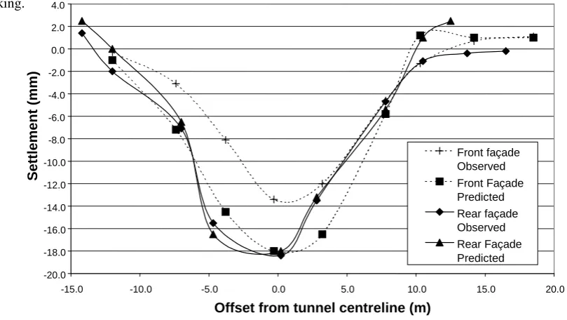
After taking baseline measurements when the bore was more than 30m from the cottages, daily monitoring was carried out as the bore proceeded beneath. Greenfield settlement profiles were obtained both at a section distant from the cottages and a section on the footpath in front of them. The settlements finally stabilised after two weeks, although the majority of settlement occurred in the first four days after the tunnel face passed. The maximum settlements observed were 13.4mm at the front, 18.4mm at the rear and 12.8mm on the footpath (Fig. 5). Cottage A Cottage H 18.5o Tunnel diameter 11m approx.
Direction of tunnel
advance 4.4m
7.6m 16.8m
[image:4.595.69.543.65.275.2]10.9m 40o
Figure 4: Plan layout on tunnel and cottages
5 of 10
The final settlement troughs approximated reasonably well to Gaussian shapes, with a trough width parameter (i) estimated as 4.5m at the front, and a calculated volume loss of 0.15% - 0.20%.
The boring technique inevitably has a significant influence on the resulting ground movements. The main causes of movement were expected to be radial ground loss, caused by slight overbreak when cutting the slot, and deflection of the primary lining. Face loss might be expected to be less significant than in a typical tunnelling operation in soft ground, due to the presence of the chalk in the heading and due to the restraint provided by the prevault and reinforcement. In-tunnel displacements of the primary lining were recorded in detail, with crown settlements of about 12mm (Morgan, 1999), and convergence of at most 8mm (4mm each side). If this movement were transmitted to the surface, it would form a significant proportion of the total settlement.
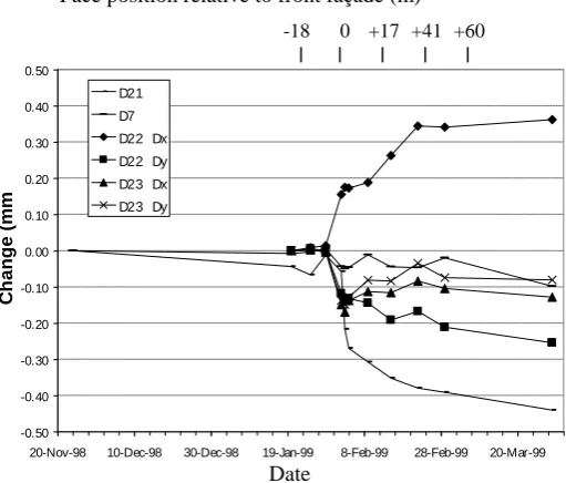
The Demec studs on the front of the cottages within the settlement trough recorded some slight movements (Fig. 6). Some cracks were observed to open, some to close, and some did not move significantly. The magnitudes of the typical movements, at 0.4mm – 0.5mm, represent a damage category of Very Slight in the Burland et al (1977) classification. The readings at the rear were similar. The damaged cottage at the southern end was outside the observed settlement trough, and although movements of cracks of up to 2mm were observed over the duration of the project, they were not strongly correlated in time with the passage of the tunnel heading.
An inspection of the cottages one month after tunnelling revealed two significant cracks that were not thought to be pre-existent. Both were vertical cracks high up in party walls between houses close to the tunnel axis. They are consistent with cottages C and D being subjected to a greater settlement at the rear than at the front, as supported by the observed settlement troughs. A further inspection three months after tunnelling did not show any further change. A damage evaluation based on the method of Burland and Wroth (1974), applying the observed settlement trough for the cottages, gives an expected damage category of “Slight”. The observations are more consistent with “Very Slight” damage.
4. Three-Dimensional Finite Element Analysis
The model was developed after construction of the tunnel, as part of the project to validate the modelling approach developed previously at Oxford (see also Bloodworth and Houlsby, 1999). The aim was to reproduce the greenfield settlements and then introduce the building to investigate interaction effects. The emphasis was on
-0.50 -0.40 -0.30 -0.20 -0.10 0.00 0.10 0.20 0.30 0.40 0.50
20-Nov-98 10-Dec-98 30-Dec-98 19-Jan-99 8-Feb-99 28-Feb-99 20-Mar-99
C h a ng e ( m m ) D21 D7
D22 Dx D22 Dy
D23 Dx D23 Dy
0
-18 +17 +41 +60
Face position relative to front façade (m)
[image:5.595.74.330.259.477.2]modelling the transverse behaviour of the terrace, excavating the entire tunnel in one stage. Further analysis using an incrementally advancing tunnel is currently in progress.
The development of the geometry of the facades of the terrace was simplified as shown in Figures 7(a) and (b), with the front and rear facades modelled as straight and the party walls between cottages included in the model. The tunnel passes beneath the terrace as shown in Figure 7(b). The finite element mesh for the ground is shown in Figure 7(c) and Figure 8.
[image:6.595.77.522.198.341.2](a) Outline plan of cottages (b) Tunnel and simplified building outline (c) Mesh on ground surface Figure 7: Development stages for the finite element model
The masonry was modelled as 220mm thick with a self-weight of 20kN/m3 and a stiffness of 2.0GPa. The windows in the facades to the front and rear were modelled as vertical regions with the stiffness reduced by 40%. This method has been found to give an acceptable representation of the effect of openings, particularly for the overall behaviour of the structure, without the drawback of mesh refinement required to model individual openings (Bloodworth and Houlsby, 1999). The tunnel was modelled as 10m diameter, lined and with an axis level 10m below ground level.
The ground above the axis of the tunnel, weathered chalk and brickearth, was modelled with the multi-surface plasticity model with an undrained strength profile with depth
z
in metres below ground level su = 60 + 28z
(kPa) and a ratio G/su of 1500. The competent chalk below axis level was modelled as an elastic material. The
mesh density in the ground beneath the building was increased until the greenfield settlement pattern was no longer sensitive to it. The complete model of the ground and building combined contained about 8000 elements and 30,000 degrees of freedom.
When the tunnel lining is modelled by shell elements, as in this model, ground loss may be controlled and modelled by applying a constant shrinkage strain to the shell elements, causing radial inward displacement of the surrounding ground. When this radial displacement was applied to the Ramsgate model, the resulting greenfield trough width parameter (i) was 11m, compared to 4.5m observed in the field. It is a common observation that
[image:6.595.76.279.381.516.2]7 of 10
analyses tend to overestimate this parameter. It appeared that the radial ground loss mechanism normally assumed for tunnels in soft ground was not entirely appropriate to this very shallow tunnel. In particular, the competent chalk below axis level would not be expected to displace significantly, other than by elastic stress relief. It was also known from the site data that deflection of the primary lining at the crown made a significant contribution to the ground movements. These effects were reproduced by shrinking only the lining above the axis level, reducing i to 5m. The shrinkage strain in the lining was adjusted to give a maximum greenfield settlement of 22mm.
When the building was included in the model, the surface settlements were as shown in Figure 9. They did not differ significantly from the greenfield case, indicating that in the model the building responded flexibly, as observed in the field (Fig. 5). Profiles of the façade settlements predicted by the model are compared with the observed settlements in Figure 10. Agreement is good, particularly at the rear. The model over-predicts the settlements at the front, which were less than at the rear probably because of the less depth of brickearth at the front (Fig. 2).
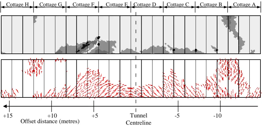
The effects of the tunnelling settlements upon the model of the building are shown in Figures 11 to 13 for the front façade, rear façade and a party wall above the tunnel respectively. The party walls suffered progressively less damage with distance from the tunnel axis. For each façade, the crack strain is contoured according to the categories in Table 1. In addition the crack pattern is illustrated by a method in which a single line is drawn at each stress point for which the crack strain exceeds 500 The direction of the line indicates the expected crack direction and its thickness the severity of cracking.
[image:7.595.71.299.266.438.2]Metres
Figure 9: Surface settlements from fully-coupled model (Heave)
-20.0 -18.0 -16.0 -14.0 -12.0 -10.0 -8.0 -6.0 -4.0 -2.0 0.0 2.0 4.0
-15.0 -10.0 -5.0 0.0 5.0 10.0 15.0 20.0
Offset from tunnel centreline (m)
S
ett
lement
(
mm
)
[image:7.595.90.495.531.759.2]Front façade Observed Front Façade Predicted Rear façade Observed Rear Façade Predicted
It may be seen that the facades are mainly undamaged, but where damage occurs it is mainly of Very Slight category, with isolated areas of greater damage. The average damage category for the facades is Very Slight.
5. Summary and conclusions
The Ramsgate Harbour Approach Tunnel case history was of a large diameter tunnel passing at shallow depth beneath a row of masonry cottages. Ground and structure movements were monitored carefully on site. The trough width was approximately equal to the tunnel diameter, and was strongly influenced by construction method and ground conditions: ground loss was very low and occurred mainly at the crown, and crown deflections of the primary lining contributed significantly. The global response of the building was observed to be flexible, following the greenfield trough. Observed damage to the masonry was less than predicted from
Cottage A Cottage B Cottage C Cottage D Cottage E Cottage F Cottage G Cottage H
Tunnel
Centreline Offset distance (metres)
+5 +10
[image:8.595.84.513.124.336.2]-10 -5 +15
Figure 11: Front façade damage category (key on Figure 13) and crack pattern, viewed from front of cottages
Cottage H Cottage G Cottage F Cottage E Cottage D Cottage C Cottage B Cottage A
Tunnel Centreline Offset distance (metres)
-10 -5
+5 +10
+15
[image:8.595.84.510.375.580.2]9 of 10
conventional analysis methods, and mainly consisted of movements of existing cracks, with a small amount of new cracking.
A three-dimensional finite element model of the site including the building was analysed. It was possible to reproduce the observed settlement trough. The response of the building modelled as planar facades was globally flexible, thus for this shallow tunnel and rather flexible buildings the necessity for a coupled analysis is not as strong as in other cases. The level of damage predicted agreed with observations. The damage predicted included some cracking starting from the top of the façade in the hogging region, which was not observed on site.
Acknowledgements
This work was funded by Brown & Root Ltd and the Royal Commission for the Exhibition of 1851. Calculations were performed at the Oxford Supercomputing Centre.
References
Augarde, C.E. (1997). Numerical modelling of tunnelling processes for assessment of damage to buildings. D.Phil. Thesis, University of Oxford.
Augarde, C.E., Burd, H.J. and Houlsby, G.T. (1995). A three-dimensional finite element model of tunnelling. G.N. Pande & S. Pietruszczak (eds.) Proc. 5th Int. Symp. on Numerical Models in Geomech. - NUMOG V, Davos. Balkema: Rotterdam, 457-462.
Augarde, C.E., Burd, H.J. and Houlsby, G.T. (1998). Some experiences of modelling soft ground tunnelling using three-dimensional finite elements. A.Cividini (ed.) Proc. 4th Eur. Conf. on Numerical Methods in Geotech. Eng., Udine. Wien:Springer-Verlag, 603-613.
Bloodworth, A.G. and Houlsby, G.T. (1999). Three-dimensional analysis of building settlement caused by shaft construction. Proc. Int. Symp. Geotech. Aspects of Underground Construction in Soft Ground, Tokyo, 19-21 July, Balkema: Rotterdam, 607-612.
Boscardin, M.D. and Cording, E.J. (1989). Building response to excavation-induced settlement. ASCE Journal of Geotech. Eng., Vol. 115, No. 1, 1-21.
Burd, H.J., Houlsby, G.T., Augarde, C.E. and Liu, G. (2000). Modelling the effects on masonry buildings of tunnelling-induced settlement, ICE Proceedings - Geotechnical Engineering, Vol. 143, No. 1, Jan., 17-29.
Severe
Moderate
Slight
Very Slight
[image:9.595.73.509.77.213.2]Negligible
Burd, H.J., Houlsby, G.T., Chow, L., Augarde, C.E. and Liu, G. (1994). Analysis of settlement damage to masonry structures. I.M. Smith (ed.) Proc. 3rd Eur. Conf. on Numerical Methods in Geotech. Eng., Manchester. Balkema: Rotterdam, 203-8.
Burland, J.B., Broms, B.B. and de Mello, V.F.B. (1977). Behaviour of foundations and structures. State-of-the-Art Report, Proc. 9th Int. Conf. Soil Mech. and Foundation Eng., Balkema: Rotterdam, Vol. 3, 495-546.
Burland, J.B. and Wroth, C.P. (1974). Settlement of buildings and associated damage. Proc. of Conf. on Settlement of Structures, Cambridge, UK, 1974, 611-654.
Crow, M.R. and Newman, T.G. (1999). Tunnelling using the pre-vaulting system in chalk for the Ramsgate Harbour Approach Tunnel, United Kingdom. Proc. Int. Symp. Tunnel Construction and Piling, London, Sept.
Houlsby, G.T. (1999). A Model for the Variable Stiffness of Undrained Clay. Proc. Int. Symp. on Pre-Failure Deformation of Soils, Torino, 26-29 September, Balkema: Rotterdam, Vol. 1, 443-450.
Houlsby, G.T., Liu, G. and Augarde, C.E. (2000). A tying scheme for imposing displacement constraints in finite element analysis. Comm. in Numerical Methods in Eng., Vol. 16, No. 10, October, 721-732.
Liu, G. (1997). Numerical modelling of settlement damage to masonry buildings caused by tunnelling. D.Phil. Thesis, University of Oxford.