Abstract— Burnishing is cold working and chipless machining carried out to improve surface roughness, surface hardness, fatigue, compressive stress and corrosion resistance by using sliding speed, feed rate and depth of penetration. The process smooths out peaks and valleys on the surface. This paper described the process carried out by multi-roller burnishing fitted in housing and rotated freely in a horizontal axis. The work material used was copper and aluminum. The process produced good surface roughness and hardness at high rotation of spindle coupled with high feed rate and constant depth of penetration.
Key words— Burnishing, Cold working chip-less, Hardness, Vertical burnishing, Surface roughness, Surface hardness
I. INTRODUCTION
oller burnishing is an iterative mechanical process, mostly used on a lathe / milling machine to induce superficial plastic strain to reduce the surface roughness of cylindrical machined parts with some advantages. This operation avoids costly supplementary grinding operations. Additionally, this finishing procedure has less impact on the environment than most other processes. The roller burnishing principle is to use, instead of a cutting tool, a free roller that will sweep the cylindrical surface of the machined part. A force, whose direction is normal to the machined cylinder, is applied to the roller in order to generate high local stresses that will induce the plastic strain necessary to smooth surface irregularities. Burnishing is a cold working process in which plastic deformation occurs by applying a pressure through a very hard and smooth roller or ball on a metallic surface. Improvements in surface finish surface hardness, wear resistance, fatigue resistance, yield and tensile strength and corrosion resistance can be achieved by the application of this process [1-3]. Most authors have been involved in studying the effects of burnishing force, burnishing feed, burnishing speed and
Dr.Sivaprakasam Thamizhmanii is working in the DRB-HICOM University of Automotive Malaysia (DHUAM), 26607 Pekan, Pahang, Malaysia from May 2015 till date. email:
Prof. Dr. Rasool Mohideen is working as Professor in B.S.Abdur Rahman University, Chennai, India. email:[email protected]
Prof. Dr. Sulaiman Hasan is working as Professor in the University Tun Hussein Onn Malaysia (UTHM), Batu Pahat,
Johor, Malaysia. email: [email protected]
number of burnishing tool passes on metallic components [4-6]. An increase in initial surface roughness will cause an increase in the final surface roughness of the ball burnished work pieces. An increase in the initial surface hardness will cause a decrease in the reduction of surface roughness, and in the total amount of the increase in surface hardness [7]. Rajasekariah and Vaidyanathan [8] advised that an increase in initial surface roughness should lead to a sharp reduction in the quality of the burnished surface. Later, Murthy and Kotiveerachari confirmed these results using higher burnishing forces [2, 8]. Adel Mahmood Hasan and Ayman Mohammad Maqableh [9] have found that an improvement in surface finish and an increase in surface hardness can be achieved in subjecting the metallic components by ball burnishing. SThamizhmanii et al. [10] stated that the surface roughness has increased as the spindle rotation, feed and depth of penetration increased for aluminum, brass and copper. If the over lapping of the roller is maintained, and then it is possible to achieve lower surface roughness value. SThamizhmanii et al. [11] have conducted experiment in burnishing process on Titanium alloy metal by applying suitable process parameters. It was found that surface hardness also increased as the spindle speed, feed rate and depth of penetration was increased. A higher surface hardness value obtained at 1400 spindle rotation with 300 feed rate and 0.35 mm depth of penetration.
II. EXPERIMENTAL PROCEDURE A. Experimental details
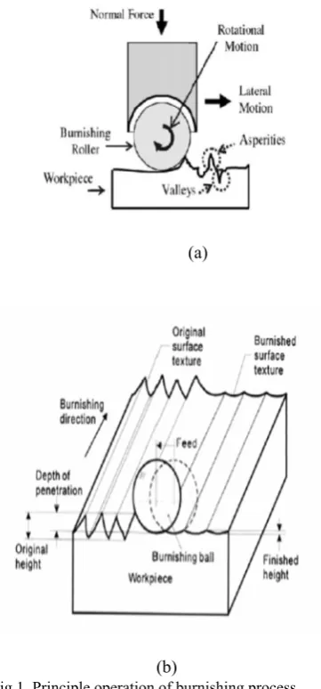
The commercially available copper block and aluminum was machined to 100 x 45 x 45 x 100 mm rectangular block. The machining was done in a CNC MAZAK milling machine and the initial surface harness and surface roughness was measured. The initial hardness was 107 HV for copper and 106 HV for aluminum and surface roughness was 4.2 microns as machined. A multi-roller burnishing tool is fitted with hardened rollers in housing and is rotate freely in a horizontal axis. The rollers are projected by 1 mm from the housing surface. The principles operation of burnishing is shown in the figure 1 (a) and (b). The asperities of the surface are smoothed down to almost flat surface. The surface roughness was measured using Mitutoyo SJ 400 model. The surface hardness was measured using Highwood –digital micro hardness tester – make HWMMT-X3 manufactured by TTS unlimited INC, of Japan. The Vickers hardness was measured with 1000 kg load. Table 1 shows operating parameters.
Vertical Multi Roller Burnishing on
Copper and Aluminum Metal
SThamizhmanii, Rasool Mohideen, Sulaiman
(a)
[image:2.595.62.243.56.444.2](b)
[image:2.595.316.504.77.184.2]Fig.1. Principle operation of burnishing process
[image:2.595.59.282.457.636.2]Fig.2. Milling machine for burnishing (Pinnacle)
[image:2.595.305.549.514.648.2]Fig..3. Vertical burnishing tool with 8 rollers
TABLE I. OPERATING PARAMETERS
Spindle rotation Feed –mm/rev Depth of penetration 700 RPM 100, 200, 300 & 400
1200 RPM 100, 200, 300 & 400 0.50 mm constant 1700 RPM 100, 200, 300 & 400
2200 RPM 100, 200, 300 & 400
III. RESULTS AND DISCUSSION A. Surface roughness- Copper and aluminum
Hassan and Maqableh [12] have identified that reduction in the surface roughness and the increase in hardness with increase in the initial hardness of the burnished work material. The plastic deformation of asperities depends on the normal force, and mechanical properties of the work piece materials, as well as geometric characteristics of the original asperities.
(b) Spindle speed of 1200 RPM
(c) Spindle speed of 1700 RPM
(d) Spindle speed of 2200 RPM
(e) Spindle speed of 700 RPM
(f) Spindle speed of 1200 RPM
Figure 4 (a) to (d) represents the surface roughness produced at various feed rates of 100, 200, 300 and 400 mm/rev using spindle rotation speeds of 700, 1200, 1700 and 2200 revolutions per minute for copper and aluminum. However, constant depth of penetration 0.50 mm was maintained throughout the experiments. At low spindle speed of 700 RPM at feed rate of 100 mm/rev. in pass1, surface roughness value was 0.26 µ and reduced to 0.21 µ at pass 3.
[image:3.595.305.544.552.681.2](h)Spindle rotation 2200 RPM
Fig.4. (a) to (d) Spindle rotation versus surface roughness for copper and (e) to h at for aluminum four feed rates for copper.
In the same pattern, at 700 rpm with feed rates of 200 from pass 1 to 3, low surface roughness value 0.22 to 0.20 µ was obtained respectively. At final experimental work for 700 RPM at feed rate of 400, the surface roughness remains constant to a value of 0.17 µ. It is clear from the results that no further deformation possible which makes the surface smoother. As the burnishing tool is passed three times for the same operating parameters, the asperities are smoothed out and fine spaced surface is obtained. Figure 4 (e to f) represents surface roughness for aluminum for the same parameters mention for copper and aluminum. While burnishing the aluminum material, it is softer than copper, surface roughness is much smoother than formed material. Figure 4 h shows the lowest surface roughness of 0.04 micron obtained at spindle rotation of 2200 RPM at feed rate of 400 mm/rev. The reasons mentioned for the low surface roughness for copper material is wholes good for aluminum material also.
B. Surface hardness for copper and aluminum
Surface hardness is measure of frequent pass of the tool over the surface. When two mating components rub each other, there is generation of heat. This heat hardened the surface of the subjected material under burnishing. There is increase in the surface hardness of the material considered due to the increase in these burnishing parameters. It can be said that increase in this hardness property in a metal will cause an increase in its resistance to deformation, so that there reduction in roughness and increase of hardness and this will be limited by the increase in the initial hardness of the work surface. Figure 5 (a - d) and (e - f) shows the surface hardness for copper and aluminum respectively.
(a) Spindle speed of 700 RPM
(b) Spindle speed of 1200 RPM
(c) Spindle speed of 1700 RPM
(d) Spindle speed of 2200 RPM
(f) Spindle speed of 1200 rpm
(g) Spindle speed of 1700 rpm
(h) Spindle speed of 2200 RPM
Fig.5. (a) to (d) Spindle rotation versus surface hardness for copper and (e) to (h) for aluminum.
The copper is little hard material than aluminum and initial surface hardness was more than surface hardness of the aluminum. The initial surface hardness of copper and aluminum is 108 and 105 respectively. As the feed rate was increased 100 to 400 mm/rev. from pass1 to passs3, the surface hardness also increased from 122 HV from pass to 135 HV at the end of pass3. It is shown in the Figure 5 (a). Similarly, for every spindle rotation from 1200, 1700 and 2200 RPM, the surface hardness increased. Figure 5 (b to d) shows the increase in the surface hardness. While burnishing aluminum, the surface hardness was 119 HV at feed rate of 100 mm/rev. at spindle rotation of 700 RPM,
the hardness increased to 137 HV. As the spindle rotation increased 1200, 1700 and 2200 RPM for various feed rates, the maximum hardness was 230 HV obtained at 1700 RPM and at feed rate of 400 mm/rev. The various hardness values obtained is shown in the figure 5 (e to h). The maximum hardness obtained was due to more heat generation which subsequently changes the surface hardness. This lead to an increase in the internal compressive residual stress, which in turn causes a considerable increase in the surface hardness. The surface hardness increases with increase in the spindle rotation, feed and a constant depth of penetration. Here, also there is a limit beyond which it is not possible to increase the hardness due to work hardening effect.
IV. CONCLUSION
The following conclusions are drawn from the experiments on copper and aluminum.
01. The experiments are useful in improving the quality of the burnished surface by selecting proper input parameters. 02. The surface roughness has increased as the spindle rotation and feed rate for copper and aluminum. If the over lapping of the roller is maintained, and then it is possible to achieve lower surface roughness value.
03. The micro hardness also increased as the spindle speed, feed increased for all the two non-ferrous metals. The work hardening effect has increased at higher operating parameters.
04. The burnishing is good process to improve the surface roughness for metals where grinding is not possible due to wheel loading effect in material like aluminum etc.
ACKNOWLEDGMENT
The authors thank The Ministry of Higher Education Malaysia (MOHE) and the Management of DRB HICOM University of Automotive Malaysia (DHUAM).
REFERENCES
[1] A.M. Hassan, A.S. Al-Basharat, Improvements in some properties of non-ferrous metals by the application of the ball-burnishing process, J. Mater. Process. Technol. 59 (1996) 250-256.
[2] R.L. Murthy, B. Kotiveerachari, Burnishing of metallic surfaces –A review, Prec. Eng. 3 (1981) 172-179.
[3] T. Siva Prasad, B. Kotiveerachari, External burnishing of aluminum components, JIE (India)-ME 69 (1988) 55-58.
[4] A.M. Hassan, O.M. Abd Al-Wahhab, Surface characteristics of some roller burnishing non-ferrous components, Mater. Manuf. Process. 33 (1998) 241-248.
[5] T. Moimoto, Examination of the burnishing process using a newly designated tool, J. Mech. Working Technol. 13 (1986) 257-272. [6] S. Rajesham, J.C. Tak, A study on the surface characteristics of
burnished components, J. Mech. Working Technol. 20 (1989) 129-138.
[7] Adel Mahmood Hassan and Ayman Mohammad Maqableh, The effects of initial burnishing parameters on non-ferrous components, Journal of Materials Processing Technology 102 (2000) 115-121. [8] R. Rajasekariah, S. Vaidyanathan, Increasing the wear resistance of
steel components by ball burnishing, Wear 34 (1975) 183-188. [9] Adel Mahmood Hassan and Ayman Mohammad Maqableh,
[10] S. Thamizhmanii*, B. Saparudin, S. Hasan, A study of multi-roller burnishing on non-ferrous metals, Journal of Materials and
Manufacturing Engineering, Volume 22,, Issue 2,June 2007.
[11] S. Thamizhmnaii*, B. Bin Omar, S. Saparudin, S. Hasan, Surface roughness investigation and hardness by burnishing on titanium alloy, Journal of Materials and Manufacturing Engineering, Volume [12] A.M.Hassan and A.M. Maqableh, The effect of initial burnishing