Abstract— The parking brake cable in the brake system of a vehicle is an important part in the car. A new material needs to be studied; thus, this paper proposes the analysis and comparison of the results between real testing data and the simulation analysis using a Finite Element model of the part, new casing cap in parking brake cable. To validate and compare the results that can be used practically according to the qualifications and standards, the properties of the new product design, casing cap made from polyamide fiberglass composite, are investigated. By analyzing and comparing these results with the FEA design, the advantages of reduction of the weight and cost in the design process can be achieved. As show in the experimental and simulation results, the error less than 30% of the maximum pull load can be achieved.
Index Terms—Plastic casing cap, Finite Element Analysis (FEA), JASO F903-75, tensile tester
I. INTRODUCTION
ODAY’S automotive industry has continued to grow and compete rapidly, which has been influenced from the consumers. In the vehicle system, the most important systems to carry out the safety function is the brake system which acts to slow down the speed of the vehicle and stop it from moving. When the vehicle is stopped, the parking brake cable can be pulled to ensure the brake action and the vehicle stopping. While the hand-brake tensile strength is being handed over to the cable, the generated braking power will be assigned to the wheel hub and the brake pressure. This mechanism generates the proper friction at the disc brake or drum brakes and then the wheels are locked. There are several standards to ensure the quality of the brake cable such as JASO F903-75 in [1].
In the analysis technique in material design, peridynamics is a new nonlocal theory that provides the ability to represent displacement discontinuities in a continuum body without explicitly modeling the crack surface. An explicit dynamics implementation of the bond-based peridynamics formulation was presented to simulate the dynamic fracture process in 3D elastic solid [2-3]. The discontinuous Galerkin (DG) approach is utilized to formulate the classical
peri-Manuscript received October 10, 2016; revised November 25, 2016. (This work was supported by the AMI (DSTAR), KMITL under the research grant no. DSTAR-RESERCH-01-58-02M.)
Siwawong Buthgate is with the college of advanced manufacturing innovation, King Mongkut’s Institute of Technology Ladkrabang. (e-mail: [email protected]).
Anakkapon Saenthon is with the college of advanced manufacturing innovation, King Mongkut’s Institute of Technology Ladkrabang. (e-mail: [email protected]).
Somyot Kaitwanidvilai is with Faculty of Engineering, King Mongkut’s Institute of Technology Ladkrabang. e-mail: [email protected]).
dynamics governing equation. As the results indicated in [2], the spatial integration can be carried out through finite element approach to enforce the boundary conditions, constraints, contacts as well as to handle the non-uniform mesh in the engineering practices [2]. The conclusion ofthe explicit dynamic formulas and numerical algorithms of bond-based peridynamics model to predict the damage of 3D brittle material has been shown in [3]. In contrast to the mesh free version of peridynamics, the discontinuous Galerkin weak form of the peridynamics governing equations is considered [2-3]. The transfer of heat through the material shapes was analyzed using Finite Element software and be compared with the shadow graph technique, the technique that can be applied to a movement of hot air as transparent media. This paper stated that the simulation results were differed from those of the experiments because some factors such as friction loss, the density of the air with during the entrance temperature of the hot air flowing, the heat loss change, etc. were not taken into consideration [3-4]. The effects of various factors on stress in a horizontal pressure vessel and the saddle supports using finite element method in the 3D form and a quarter finite element model were presented [4-5]. The ratio of the distances between the support from the end of the vessel and the length of the vessel, and the ratio of the length of the vessel to the radius of the vessel were used as the important variables in the design.
In addition, the effects of stress on the variation in the pressure tank horizontal support and stand by Finite Element was studied in [5]. This work demonstrated the techniques to improve the elements to simulate the stress on the tank and the pressure; the supporting platform has been decreased [5]. The fracture criteria for ductile materials have been developed in numerous researches; however, there are several huge differences among them. In the simulation, it is necessary to find a way to select or determine a ductile fracture criterion and identify its applicability and reliability. In the study in [6], a finite element aided testing (FAT) method was proposed to obtain the uniaxial full-range constitutive relationship up to the failure of A508-3 steel and SS316L. The fracture stress and strain are obtained based on finite element analysis. Summary of the FAT method for acquiring the full range constitutive relationship up to the failure of ductile material has been developed. The validity of FAT method was verified by the use of different ways of loading (tensile and compression) and different types of specimen configurations. By applying the full-range constitutive relationships obtained by the FAT method and the fracture criteria considering the stress tri-axiality, the ductile fracture toughness of A508-3 steel and SS316L was possible to be predicted without the ductile crack growth test
Reliability Design Optimization of Casing Cap
by Sample Test and FEA
Siwawong Buthgate, Anakapon Saenthon and Somyot Kaitwanidvilai
[6]. Multi-chamber perforated resonator (MCPR) is a kind of typical silencer element which can both attenuate the broadband noise and gain the specific installation requirements. The one-dimensional transfer matrix method (TMM) and finite element method (FEM) were widely used to predict the transmission loss of the resonators [7]. This approach is very applicable to non-uniformly distributed perforations with large diameter and high perforation rate. Obviously, FEM can reproduce the test results within the entire frequency range. Such method can be used to verify the TMM results and compensate the TMM’s inaccuracy before prototyping [7]. Two different computational approaches, namely the finite element method (FEM) and meshless finite difference method (MFDM), in one domain were proposed to solve the thermomechanical initial– boundary value problem where the heat transfer of the domain is non-stationary. In this method, the domain was divided into two subdomains, those are FEM and MFDM. Contrary to the other coupling techniques, the approach presented in this paper [7] was defined in terms of mathematical problem formulation rather than the approximation level. The thermomechanical initial– boundary value problem has been solved by means of the computational method that couples the two well-known discrete solution approaches, the finite element method and meshless finite element method (FEM/MFDM). Immersed finite element (IFE) method are an efficient tool to solve the interface problems on a Cartesian mesh, which is desirable used in many applications to cope with the periodic boundary condition [8]. The new matrix is used to maintain the symmetric positive definite so that the linear system can be solved efficiently. The results of the IFE method for an unbounded elliptic interface problem with periodic structure were shown in this paper [8]. The periodic boundary conditions can be accommodated by modifying the stiffness matrix [9] using the two-step implicit–explicit (IMEX) time discretization coupled with finite element methods for solving the delayed predator–prey and reaction–diffusion systems. Finite element methods were used to discretize the space variables, both IMEX two-step one-leg and IMEX linear two-step methods were considered in the time domain discretization, where the nonlinear reaction part is discretized explicitly and the diffusion part is discretized implicitly. Finite element methods are used to discretize the space variables, and it is shown that the error estimateed with handling the breaking points can be evaluated. Numerical experiments in [9-10] confirmed the theoretical results. In [10], the static analysis of linear–elastic structures with uncertain parameters subjected to deterministic loads was addressed. The uncertain structural properties are modeled as interval variables with assigned lower bound and upper bound. The key idea of the novel method is to associate an extra unit interval to each uncertain parameter in order to keep physical properties linked to the finite elements in both the assembly and solution phases. This allows one to reduce overestimation and perform the standard assembly of the interval elementary matrices. The key idea of the method is to model the uncertain parameters as interval variables handled by
interval (IIA via EUI), recently introduced in the literature to reduce the overestimation affecting the classical interval analysis [10].
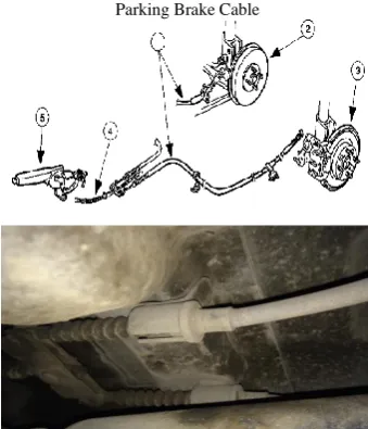
[image:2.595.345.505.244.337.2]This article aims to compare the results of analysis of the strength of casing cap using Finite Element (finite element method) and the test results. The material design used is plastic composite which is aimed to be used instead of steel to gain the advantages of lower weight and cost. Fig. 1 shows the parking brake cable connecting with the rear wheels and the operation lever brake system of the driver's seat. Pull the hand brake by the driver will send the force passing to the brake system control which is used for parking.
Fig. 1 layout of the parking brake cable in the car
[image:2.595.340.510.381.579.2]Parking Brake Cable
Fig. 2 Function of the parking brake cable
[image:2.595.308.553.679.728.2]Fig. 2 shows the location and function of the parking brake cable and the piece of casing cap, which is used as a sheet plate of the car and lock the clip to be put together. As shown in Fig. 2, there are 9 components of the parking brake cable which are detailed in Table I.
TABLE I
DETAILS OF THE COMPONENT ON THE PARKING BRAKE CABLE.
No Components Function
1 Inner ends Supporting the loading and connecting the related parts
2 Boot Protecting dust and water
3 Casing caps Reflecting the strong support and connect related parts
4 Inner cable Loading capacity and pass it driven 5 Outer casing Reflecting the strong support for protecting
and maintaining the inner cable routing 6 Clamp Keeping the routing of cables 7 Protector Protecting the outer casing
8 Casing caps Reflecting the strong support and connect related parts
9 Inner ends Supporting the loading and connect related parts
Fig 3 shows the photos of the component of the parking brake cable.
II. THE PROPOSED DESIGN AND FEM
The design of new parking brake is based on the value engineering (VE), which is a method that has been used for a long time to split the costs, which are in various functions, whether the assembly or parts production. This technique allows the designers to design with fewer mistakes by analysis. This paper focuses on the reduction of the product cost and maintaining the quality of the casing cap part which is one of the techniques in VE [11].
Finite Element Method: The analysis by finite element used in this design can be divided into 6 steps as follows:
Step 1 Break the problem into the domain of small elements which the element is connected with the others by a point called node.
Step 2 Select the functional model which are mainly selected as a polynomial equation in this design.
Step 3 Create a physical equation for each element and form all equations as the matrix below.
Step 4 Select the boundary conditions suitable for the system.
Step 5 solving the system of equations to determine the value of the possible solutions.
Step 6 Calculate the amount of any other interests.
The shape of any object in three dimensions tons x-y-z coordinates on a thin part of this material may be clamped firmly fixed (Fixed) while the skin may be an external force acts. The thin part may be released independently by the (Free Boundary) domain of the object shape tones which can be divided into elements 3D tetrahedron (Tetrahedral Element) subsidiary [12].
{σ} = [c]{ɛ-ɛ0} (1)
Vector equations contain
{σ}= σx , {ɛ}= ɛx (2)
σy ɛy
σz ɛz
τxy γxy
τyz γyz
τxz γxz
ɛx, ɛy, ɛz is the stress on the axes x, y, z, respectively.
γxy, γyz, γxz is the shear strain on the axes x, y, z,
respectively
[c] is the flexibility of the matrix material
The constraint equation is
(3) Where
E = the modulus of elasticity v = the Poisson's ratio
III. CASING CAP DESIGN AND RESULTS
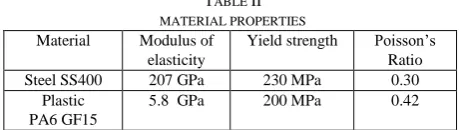
At present, the casting cap is made from the steel material (SS400) which causes the heavy weight of car body and high material cost. One of the most interesting materials attempted to be studied in this research work is PA+GF15 plastic which is more lightweight and low cost material [13]. Table II shows the properties of both materials, SS400 and PA+GF15.
TABLE II MATERIAL PROPERTIES Material Modulus of
elasticity
Yield strength Poisson’s Ratio Steel SS400 207 GPa 230 MPa 0.30
Plastic PA6 GF15
5.8 GPa 200 MPa 0.42
The objective of the designed parts, casing cap, is to replace the steel SS400 with the plastic PA6 GF15. The new design part must be complied with the maximum pull load force described in the standard JASO F903-75, the standard of cable for the automotive industry. In addition, the maximum value of the pull load for casing cap is 18 kgf (Refer to the Jason standard table 17 casing cap type D2). To ensure and confirm the specification of the new design, the FEM with the parameters in Table III was applied to simulate the stress, stain and max. pull load force on the new part.
TABLE III
PARAMETERS IN THE FEM
Finite Element Program:
Element shape
Topology Meshing value MSC Nastran
software
Tetrahedron Tetrahedron 10 nodes
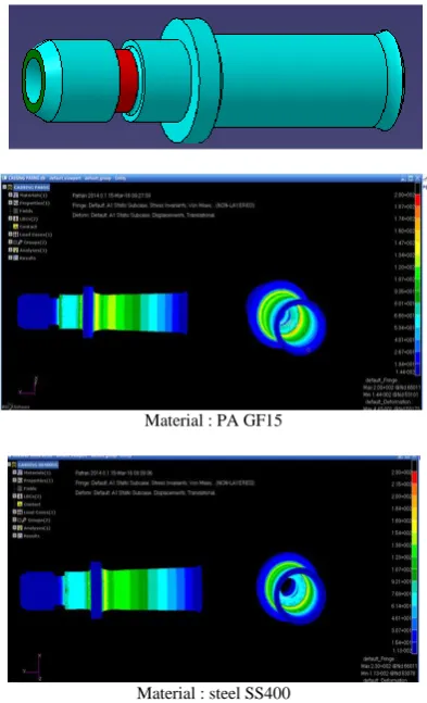
[image:3.595.310.540.501.566.2]By using the CAD files and assigned material properties, the analysis of the designed casing cap can be achieved. Fig. 5 shows the FEM analysis on the two simulations of casing caps.
Material : PA GF15
[image:4.595.70.267.116.440.2]Material : steel SS400
Fig. 4 Finite Element Analysis on the 2 different casing caps.
As seen in Fig. 4, the similar strain values, safety factor and maximum pull of the load can be analyzed.
PA GF15 Maximum pull of load : 471 kgf, Safety factor = 1.0
Steel SS400 Maximum pull of load 505 kgf, Safety factor = 1.0
The testing was carried out by the tensile testing machine 2000 kgf, Hungta instrument, maximum speed 20 m/s. To ensure the stability of the developed parts, 100 samples of each type of casing cap were tested and compared with the simulation results. Figs. 5 and 6 show the maximum pull load from FEM and real experiments. As seen in the figures, the real pull of load is differed from the simulation. The mean values of the difference can be calculated as: 146.46 kgf for Steel SS400, and 132.12 kgf for the plastic PA GF15.
As seen in the figures, the maximum pull of load values of the casing cap made from both materials are nearly the same values. However, almost of the real pull load values from the experiments is higher than those of the FEM. As seen in the calculation, the difference values between the simulation and experimental results are 22.48% for the plastic casing cap and 28.05 % for the steel casing cap. As
[image:4.595.308.545.152.308.2]pull load values; however, considering the weight and cost of the steel, the plastic is an attractive material for the casing cap. The weight of the plastic is approximately 30% of the weight of steel and the cost is about 50% of the cost of steel. Thus, based on these factors and the enough pull load values, the plastic casing cap can be applied instead of the steel casing cap.
Fig. 5 Results of the real pull of load of the Steel SS400 casing cap: from the experiments and the FEM.
Fig. 6 Results of the real pull of load of the plastic PA GF15 casing cap: from the experiments and the FEM.
IV. CONCLUSION
From the results and analysis, this research work can be summarized as follows:
The results of the FEA model and the sampled test model of the tensile test machine are different; however, considering the natural error of the material and the complex shape of the object, the magnitude of the difference is acceptable, and the FEA model can be used to design and improve the new casing cap.
The results of the analysis in this research work suggest that based on the simulated values of the pull of load from finite element method and pull of load from sample tests, all casing caps with 2 type different materials comply with the standard of the control cable, JASO F903-75 standard.
Considering the cost and weight, the composite plastic Pa6 GF15 is an attractive material for the future casing cap. In addition, the new trend of the eco-car aims to save the energy when operating. This requires lighter weight of the
400 425 450 475 500 525 550 575 600 625 650 675 700
0 20 40 60 80 100
pull of load FEM
350 400 450 500 550 600 650 700
0 20 40 60 80 100
[image:4.595.309.546.354.497.2]REFERENCES
[1] Japanese Automobile Standard, JASO F903-75, 1975.
[2] Bo Ren , C.T.Wu, E. Askari. “A 3D discontinuous Galerkin finite element method with the bond-based peridynamics model for dynamic brittle failure analysis,” International Journal of Impact Engineering, Vol. 99, pp. 14–25, 2016.
[3] Wuttichai Sittiwong. “Study of Hot Air Flow Behavior using EasyFEM Simulation and Shadow graph Techniques,” Journal of Thonburi university, Vol. 8, pp. 1-14, 2015.
[4] Attaphon Chaimanutsakul. “A study of stress in a horizontal pressure vessel and the saddle support using finite element method,” Journal of Thonburi university, Vol. 8, pp. 1-9, 2013.
[5] Di Yao,LixunCai , ChenBao. “A new fracture criterion for ductile materials based on a finite element aided testing method,” Materials Science&Engineering, Vol. A673, pp. 633–647, 2016.
[6] Rong Guo , Wen-bo Tang, Wei-wei Zhu. “Comparison of 1D transfer matrix method and finite element method with tests for an acoustic performance of multi-chamber perforated resonator,” Applied Acoustics, Vol. 112, pp. 140–146, 2016.
[7] J. Jaśkowiec, S. Milewski. “Coupling finite element method with meshless finite difference method in thermomechanical problems,” Computers and Mathematics with Applications, Vol. 72, pp. 2259– 2279, 2016.
[8] Yong Cao, Yuchuan Chu, Xiaoshi Zhang, Xu Zhang. “Immersed finite element methods for unbounded interface problems with periodic structures,” Journal of Computational and Applied Mathematics, Vol. 307, pp. 72–81, 2016.
[9] Aiguo Xiao, Gengen Zhang, Jie Zhou. “Implicit–explicit time discretization coupled with finite element methods for delayed predatorprey competition reaction–diffusion system,” Computers and Mathematics with Applications, Vol. 71, pp. 2106–2123, 2016. [10] Alba Sofi, Eugenia Romeo. “A novel Interval Finite Element Method
based on the improved interval analysis,” Comput. Methods Appl. Mech. Engrg., Vol. 311, pp. 671–697, 2016.
[11]Ampika Kairit, Value Engineering VE, Bangkok, Se-education, 4th
edition, 2536.
[12]Pramote Dechaumpai, Finite Element Method in Engineering, Bangkok, Chulalongkorn center, 2nd edition, 2012.