Survey on Digital Function with Variable Power Supply
for Academic Purpose
Aparna A.
Department of ECE
Sambhram Institute of
Technology, Bangalore-97
Harshitha C.
Department of ECE,
Sambhram Institute of
Technology, Bangalore-97
Harshitha J. H.
Department of ECE
Sambhram Institute of
Technology, Bangalore-97
Joyci L.
Department of ECE
Sambhram Institute of Technology, Bangalore-97
K. Ezhilarasan
Department of ECE
Sambhram Institute of Technology, Bangalore-97
ABSTRACT
Analog electronics lab devices are very delicate instruments. The devices are Function generator, Variable Power supply, Oscilloscopes, Bread board, probes and jumpers. The most delicate instrument is the Function generator. A function generator is a universal tool used by every electrical engineer at some point in their career. Sine, square, sawtooth and triangle waves of different periods, duty cycles and amplitudes are required as input to many digital and analog circuits. A digital function generator creates these input signals which can be used in variety of applications. There is currently a wide range of commercial function generators available, many of them fetching a high price. This paper proposes three modules a Digital function generator, a voltage supply and a waveform display. Which reduces cost and occupies less space. This paper aims to generate the various waveforms commonly used in a Academic laboratory. In this project digital techniques are used to synthesize the waveforms, also to generate variable voltages that are necessary as input source for analog and digital circuits. A dual channel function generator which generates four waveforms such as Sine, Square, Triangle and Sawtooth. And a display to show waveforms to the users to analyse input and output waveforms.
Keywords
Function generator, Mechanical, Analog, IC, Computerised, Digital, DSP, DDS, Arbitrary, Square, Triangle, Sawtooth, Sine.
1.
INTRODUCTION
A function generator is a very commonly used instrument that is used in mechanics, electronics, bio-engineering, physics and many other fields. A wide variation of synthesized electrical signals and waveforms can be generated for testing, repairing and diagnostic applications. It produces different kinds of waveforms such as sine, square, triangle and sawtooth over a wide range of frequencies. As the function generator is the commonly used signal source, it is the most extensively used general instrument in the modern testing areas. The signal source is a mandatory instrument for any research, production, testing, and maintenance because each electronic component, units and the machine equipment, the signal source is necessary. It widely produces the variety of voltage signals and current signals by differing its frequencies and waveforms. When these signals are added to the device or equipment which is to be measured it is possible to observe
and measure the output response of the measuring instrument to analyze and to identify their performance parameters. Hence Function generator is the most basic and widely used electronic instruments especially in the field of electronics. It is not only being applied in the domains of education, scientific research, production and engineering, but also has some merits such as generating continuous phase transformation, frequency stabilization and so on. It is also useful in simulating various complex signal and dynamic control. Through the parameters, such as frequency, amplitude, phase and waveform the function generator is capable to communicate with other equipment to constitute automatic test system (ATS), so it can also apply in the domains of communication, ATS instruments and meters. It is being implemented with basic expensive components. For those applications which needs a signal that increases or decreases at a specific linear rate the sawtooth waveforms and triangular waveforms generating function generators are commonly used. these type of generators are also used in driving sweep oscillators in the X-axis and X-Y recording oscilloscopes. The square waveforms are used for linearity measurements in an audio-systems. The simultaneously generated sawtooth waveforms are used to drive the horizontal deflection amplifiers of an oscilloscope. Which provides visual display of the measured result. When triangle and sine waves are started simultaneously at zero crossing. It provides zero phase shift to the sine wave.
Similarly, different outputs of generator can be made available at the same time e.g. the generation of a square wave is to test the linearity of an amplifier and simultaneously provide a sawtooth to drive the horizontal deflection amplifier of the CRO to provide display. This provided the phase locking capability to function generator. A variable or regulated power supply is an embedded circuit which it converts unregulated AC into a regulated or fixed or constant DC. It converts AC supply into DC using a rectifier. It eliminates noise using filters. Its main function is to produce a stable supply voltage to a circuit or device that must be operated within certain power supply limits. The output from the regulated power supply is always DC.
2.
LITERATURE SURVEY
14 communication technique and radar technique in 1940. This
improvement changed the function generator from a qualitative investigation testing instrument to a quantitative analysis measuring instruments. At the same time, the pulse function generator to measure the pulse circuit or modulate the pulse was also invented. But the mechanical structure of the function generator was very complex in earlier time, which led the slowly evolution of the function generator. Till 1964, the function generators were only made of transistors. Initially waveform generators were designed using active and passive components. It produced only one or two types of waveforms using complex circuits. It does not use any microprocessor. It generates waveform in short range of frequencies. It has low precision and low durability. It does not use any memory.
Barker [1] has shown that there are waveforms with the desired auto-correlation function and with uniform distribution of energy. But Storer and Turyn [2] have concluded that Barker sequences do not exist that have lengths exceeding thirteen. The other method using shift-register sequences, were periodic and therefore had periodic auto-correlation functions that are uniformly equal to minus one except at the peaks. These have been independently discovered by a number of authors. [3] These functions were generated by simple recursion rules. In this example the amplitude of each component pulse in the sequence is the product of the amplitudes of the third and fourth preceding amplitudes. Shift-register sequences existed for lengths of the form 2n - 1, with n as an integer. Trains are chosen to be arbitrary length. The amplitudes of the component pulses are chosen from a continuum of values, rather than from the values plus one and minus one, while their durations are all of the same unit value. Thus the distribution of energy in these waveforms is not uniform. [4] Generation of stable sinusoidal oscillations of good waveform had been realized in a basic multivariate circuit by optimizing load and coupling elements and introducing an amplitude defining mechanism with the use of emitter coupling. The resulting differential operation introduces an inherent tendency of self-compensation against changes of active circuit parameters, and the frequency remains practically independent of change in temperature even though transistors were used [5].
Waveform generation by applying a quadrature mode of operation is also a well-known method in the field of sine wave oscillators [6], [7]. The chain of integrators and amplifiers are the main components of a sine-wave quadrature oscillator. The output of an integrator is fed as the input of another integrator connected to an inverter which feeds back to the input of the first integrator Such a system could be approximately modeled easily by a conservative [8] system of differential equations [9].
Analog Function generators were designed using active and passive components. It produced three types of waveforms using complex circuits. It had a drawback of having noise in the output waveform.
The IC 8038 is a function generator chip that can generate three basic signals such as Sine, Square, and triangle waveforms. The IC has also provided options to adjust the parameters of a waveform like frequency and duty cycle. This IC can generate signals with frequency ranges from 0.001KHz to 300KHz using external resistors and capacitors.
IC LM8038 is a function generator IC. It generates waveforms with variable frequencies and constant amplitude. The frequencies of all three waveforms are similar. This
function generator has a disadvantage of generating the single frequency for all three waveforms. It cannot generate different frequencies for individual waveforms. Since all analog components were used there existed noise at the output. Function Generator Using IC LM741 Op-Amp three waveforms such as sine, square and triangle can be generated. By changing the values of capacitor it is possible to change the amplitude of wave and also by varying resistance the frequency and time period can be varied up to the required value.
IC LM348 also generates square, triangle or sine waves in the audio range. It uses four operational amplifiers to deliver these waveforms in the 6 Hz to 7000 Hz range. Since all these function generators used analog components there existed noise at the output.
Computerized function generators [10] were evolved using microprocessors. It also produced 3-4 types of waveforms using programming concepts. But the cost of the computerized microprocessors was high. And to generate waveforms from those processors requires a deep study of such big processors. It also requires drivers and buffers to collect the analog waveform from the digital processor. The waveform generating module creates a waveform in real-time based on several parameters set by the user. The waveform generating module first takes into account a stall bit to decide whether or not to compute during the current clock cycle. If the stall bit is high, the waveform module goes on to recomputed duty cycle and step rate information for each possible type of waveform if the user made a change to amplitude, frequency, or duty cycle during the previous cycle. Finally, the waveform module accepts user input to adjust amplitude, frequency, duty cycle, or wave type and then outputs a single sample of the current waveform in real-time [11].
Digital waveform generator. This type of generator avoids the use of RC oscillators and RC filters. The evolution of digital waveform generator began with the Generation of low-frequency sine wave [12] using shift registers. It worked on the principle of the non-recursive digital filter [13] - [14]. The delayed versions of the binary waveform are obtained from a shift register for which the unit of delay can be varied directly by variation of the frequency of the clock pulses applied to the register. A sinusoidal waveform could be produced from a rectangular waveform by means of a linear continuous system having an impulse response. The binary waveform is itself generated by a feedback shift register [15]. It can even generate digital signals. This generates works on microcontrollers. Hence the hardware requirement and knowledge requirement is less compared to microprocessors. For a single application, the controller also works on a concept of a lookup table. Where the similar waveforms need not be generated for several times.
anti-aliasing filter at the input to remove erroneous signals and to smoothen the output signal. [16]. Examples of DSPs are Conexant, Lucent, Motorola, NEC, Technologies and Texas Instruments (TI). The DSP TMS320C6713 is very powerful tool, but to develop programs, a supporting architecture is required to store programs and data and to get the desired signal as output as in [17].
Direct Digital Synthesis (DDS) is a method of generating an analog signal by producing a time varying digital signal then performing digital to analog conversion. DDS technology works with three higher level hardware blocks: a sample clock, a phase accumulator, and a look-up table [18]. A DDS System is used especially for a precise, high frequency and a phase tunable output. A major advantage of a direct digital synthesizer (DDS) is that its output frequency, phase, and amplitude can be precisely and rapidly manipulated under digital processor control [19]. In this method, the waveform generated is represented as a trigonometric function. [20] The DDS is based on a frequency synthesizer that operates by storing various points and then recalling them to generate the waveform. In the DDS architecture, the look-up table is used to map the waveform [21-29] in a memory whose content is cyclically addressed to generate the output waveform. With DDS, one cycle of the desired waveform is represented digitally in a look-up table memory and the contents of such memory are read sequentially to produce a stream of digital data that represents the desired waveform [30].
Although this method has the capability to generate accurately arbitrary waveforms, it exhibits the disadvantage of requiring a large list of sampled waveform points to operate, what unfortunately implies a huge memory usage. If the sampling period is small compared to the period of the function, then the computer has to perform so many computations that it may fail to keep up with the period of the waveform. This means the computer would have a problem generating low-frequency waveforms. DDS suffers the following restrictions [31,32]; The output frequency must be less or equal to half the clocking frequency for proper reconstruction. The amplitude of the output waveform is fixed to create the need for extra circuitry to vary the amplitude. Since the waveform is created using sampling techniques the user must accept a certain amount of spectral distortion.
Arbitrary Waveform Generators (AWG), are advanced signal generators. It provides freedom to the user to generate waveforms of any desired shape, within certain limits of the frequency range, accuracy, and output level. Function generators are limited to a set of simple waveforms. The arbitrary waveform generator is much more flexible compared to a function generator. Arbitrary waveform generators are more expensive than function generators. It offers highly limited bandwidth. Therefore, Arbitrary waveform generator is used for higher-end design and test applications. It operates as conventional function generators. They generate standard waveforms such as sine, square, ramp, triangle, and noise. It also generates additional built-in waveforms such as sinx/x, cardiac waveform while other may display a graph of the waveform on their screen. Arbitrary waveform generator allows multiple channels to be operated with precisely controlled phase offsets and frequencies.
Before the evolution of oscilloscope, oscillography was invented. The oscillograph started with hand drawn chart which was later turned into automated. Then it grew into galvanometer driven recorders and photographic recorders. Then in the year 1897 Karl Ferdinand Braun built the first cathode ray tube (CRT) and the first CRT based oscilloscope
for physical experiments. In 1920s CRTs were used for measurements. The first commercially built Cathode-Ray Oscilloscope was type 535 built by the General Radio Co. of Cambridge, MA, in 1931. This instrument had three parts, the CRT was mounted on a stand, the power supply and the type 506-A as in.
In 1934, the type 687-A Electron Oscillography was invented. It consisted CRT, power supply and sweep generator, all in one housing. The Deflection sensitivity ranged from 1 to 5 Volt and anode voltage could be adjusted from 500 to 2,500 V.
In the same year Dumont invented cathode ray oscilloscope with the power supply and an internal oscillator which repeatedly sweeps a beam of electrons across the screen at constant speed. Then a cold cathode oscilloscope was invented to record transients in the microseconds and milli sseconds. Instead of cathode ray tube a high-vacuum pump was used. In 1947 the Tektronix type 511 portable wide band oscilloscope was on the market. It was more sensitive, more compact and had a wide band circuitry. This oscilloscope used a delay line and a amplifier to obtain the bandwidth of 10 MHz The screen had a precise grid to perform accurate measurement in 1954 the plug-in oscilloscope was introduced with the series 530. It consisted of distributed 14 tube vertical amplifier of 30 MHz bandwidth.
CRT based Digital oscilloscopes evolved with Dual channel 100MHz, LED indicators, TV synchronization, trigger signal output, Z axis modulation input, Signal display function, monitoring the leading edge, Continuously adjustable screen illumination and Delayed sweep.
Then Digital oscilloscopes evolved with microprocessor. It can trace as often as needed to keep events displayed for as long as the user needs. The Tektronix TPS2014 oscilloscope is a graph - displaying multicolor device. It has a bandwidth of 100 MHz, a sample rate of 1GS/s and 4 fully isolated vertical channels.
3.
PROPOSEDMODULE
16
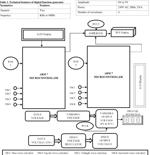
Table 1. Technical features of digital function generator
Parameters Features
Channels Two
Frequency KHz to 4MHz
Amplitude 0V to 5V
Power 230V AC, 50Hz, 5VA
Number of waveforms 4
Fig 1: Proposed module
As it contains dual channel function generator, dual voltage supply modules and a display. It replaces 5 devices into one device with one module. The features of the dual function generators are mentioned in the table1.
4.
CONCLUSION
The proposed module generates four waveforms such as sine, square, triangle and sawtooth. The waveforms are generated in two channels. It also contains a power supply module to
17
5.
ACKNOWLEDGMENTS
Thanks to the experts who have contributed towards development of the template.
6.
REFERENCES
[1] R. H. Barker, “Group synchronizing of binary digital systems,” Communication Theory, London, pp. 273-287; 1953.
[2] R. Turyn and J. Storer, “On binary sequences,” Proc. American Mathematical Society, Vol. 12, No. 3, pp. 394-399; June, 1961.
[3] E. Elspas, “The theory of autonomous linear sequential networks, ” IRE Transactions on Circuit Theory, Vol. CT-6, No. 1, pp. 45-60; March, 1959.
[4] “The generation of impulse-equivalent pulse trains” David A. Huffman Department of Electrical Engineering and Research Laboratory of Electronics Massachusetts Institute of Technology Cambridge, Massachusetts. [5] ”A Temperature-Stable RC Transistor Oscillator”
Proceedings of the IEEE March 1969, Manuscript received November 6,1968.
[6] “A Simple Quadrature Oscillator for Generating Triangular Waves and Square Waves” by Z. Kalpan, D. Har-zahav, and A.Blau; Proceedings of the IEEE, Vol. 67, No. 11, November 1979
[7] J. G. Graeme, G. E. Tobey, and L. P. Huelsman, “Operational Amplifiers Design and Applications.” New York: McGraw-Hill, 1971
[8] “AD530 complete monolithic MDSSR technical bulletin,” Analog.
[9] Z. Jacyno, “Second order conservative systems,” Automut. Contr. Devices, Nonvood, MA, July 1971, p. 8. [10] R. Chassaing, “Digital Signal Processing and
Applications with the C6713 and C6416 DSK”, John Wiley & Sons Inc., New Jersey, 2005.
[11] B.P. Kumar, “Digital Signal Processing laboratory”, CRC Press, Florida, 2005.
[12] Jouko Vankka, Direct Digital Synthesizers: Theory, Design and Applications. London : Kluwer Academic Publishers, 2001.
[13] Leis John Wiley, Digital Signal Processing Using MATLAB for Students and Researchers. New Jersey: John Wiley & Sons, Inc, 2011.
[14] “Digital Generation of Low-Frequency Sine Waves” by Anthony C. Davies, Member, IEEE Transactions Instrumentation and Measurement Vol. IMT-18. ,O.2. JUNE 1969.
[15] C. M. Rader and B. Gold, "Digital filter design techniques in the frequency domain," Proc. IEEE, vol. 55, pp. 149-171, February 1967.
[16] J. Oswalld, "Synthesize digital function transfer part convolution", Cables at Transmission, vol. 21, pp. 175-194, 1967.
[17] A. C. Davies, "Digital filtering of binary sequences," Electron. Letters, vol. 3. pp. 318-319, July 1967
[18] S.W.Colomb, Ed., “Digital Communications”. Englewood Cliffs, N. J.; Prentice-Hall, 1964
[19] Baochun H and Naeem S 2010 Real time DDS waveform generator in TI DSP. In: Proceedings of the fourth European DSP in education and research conference 241–244
[20] P. E. K. Chow and A. C. Davies, "The synthesis of cyclic code generators," Electron. Engrg., vol. 36. pp. 253-259, April 1964.
[21] R. Lyons, "Direct Digital Synthesis," IEEE SIGNAL PROCESSING MAGAZINE , vol. DOI 10.1109, no. MSP.2004, pp. 50-53, 2006.
[22] Adad Langlois W F and Al-Khalili D 2012 Arbitrary function generator using direct digital synthesis. Conference on Precision Electromagnetic Measurements 622–623
[23] Catunda S Y C, Saavedra O R, Fonseca Neto J V and Morais M R A 2003 Look-up table and breakpoints determination for piecewise linear approximation functions using evolutionary computation. In: Proceedings of the Twentieth IEEE Instrumentation and Measurement Technology Conference 1: 435–440 [24] Langlois J M P and Al-Khalili D 2003 Piecewise
continuous linear interpolation of the sine function for direct digital frequency synthesis. IEEE MTT-S Int. Microwave Symp. Digest. 1: A65–A68
[25] Lu T L and Qiu Y L 2001 An approach to the single-chip arbitrary waveform generator (AWG). International Conference on ASIC 506–509
[26] Ming-Gang G and Iuzzolino R J 2009 The design of direct digital frequency synthesis based on ROM lookup table. International Conference on Information Engineering and Computer Science 1–3
[27] Prasad S S 2007 Design of arbitrary waveform generator based on direct digital synthesis technique using code composer studio platform. Int. Symp. Signals Circuits Syst. 1: 1–4
[28] Tang P T P 1991 Table-lookup algorithms for elementary functions and their error analysis. IEEE Symposium on Computer Arithmetic 232–236
[29] Weibo H, Chung-Len L and Wang X 2008 Arbitrary waveform generator based on direct digital frequency synthesizer. IEEE International Symposium on Test and Application Electronic Design 567–570
[30] Xiaodongmn L, Yanyan S and Shubo L 2007 A MCU-based arbitrary waveform generator for SLH power amplifier using DDS technique. International Conference on Electronic Measurement and Instruments 4: 895–899 [31] Yih-Chyun J 1997 Direct digital synthesizer with jittered
clock. IEEE Trans. Instrum. Measur. 46: 653–655 [32] R. Lyons, "Direct Digital Synthesis," IEEE SIGNAL