Automated Irrigation System
Chinmay Patil
1*, Divit Shetty
2, Piyush Roy
3
---***---Abstract -
This is an automated irrigation system based onIoT. An android controlled robot performs tasks like spraying, obstacle detection, humidity sensing and temperature sensing. With the help of IoT we can control the system remotely via Bluetooth and monitor the conditions of the agricultural field without physically being there, all the data from the sensors also can be accessed from a remote location, thus this system can help in increasing yield with continuous monitoring of crop.
Key Words:Ultra sonic sensor, Bluetooth module, IoT, Temperature sensor, Humidity sensor, Automated irrigation.
1.INTRODUCTION
One of the main aspects of human survival is food which indirectly leads to agriculture. In India traditional agricultural methods are still being used which are quite inefficient. This problem can be solved by using smart agriculture systems. Introduction of automation in agriculture leads to efficient crop monitoring without any human intervention. Overall the design realizes remote monitoring and control of farms and hence reducing labour cost.
IoT based system are used as they connect all the sensor’s data and send it to a main server, where all the data can be collected and analysed. This data can then be used to improve the yield by making all the necessary changes.
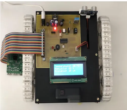
In this system, a robotic vehicle which can be controlled by a cellular phone with the help of the Bluetooth module. The system is connected to an iot web page which displays all the necessary data in real time. The data can be accessed from any remote location via the use of proper credentials for privacy purposes. The system also consists of a wireless cameras to monitor the surrounding visually. The live feed from the camera can be monitored with the help of an electronic device.
The robotic vehicle also has a temperature and humidity sensor which is used to monitor the data of the field and analyse the pattern for spraying of water, along with that an ultrasonic sensor which is mounted on the front of the vehicle to detect any obstacles and stops on detection and a buzzer is used to alert that.
A tank mounted on the vehicle which can be remotely controlled for spraying water in a particular section where it may be needed, which we can determine from the visual or the data from the sensors.
[image:1.595.308.559.374.592.2]In this paper section II is about the projects of similar domain and their work, section III and IV has the system design of project and all the components used and system description and how it works respectively. Section V contains conclusion and the future scope for the project.
Figure 1. Overview of the system
2.RELATEDWORKS
A system with soil related parameters like temperature and humidity were measured by Wireless sensor network and implemented using microcontroller and sensors. The transmission was done on hourly basis and transmitted to the webpage. The wireless robot has instruments like cutter, sprayer and camera along with various sensors. Using them it is used for Keeping vigilance, spraying of pesticides and scaring birds and animals. [1]
1,2,3StudentofB.TechElectronics&Telecommunication,NMIMSUniversity’sMPSTME,Mumbai,
Crops in the early growth stage diseases easily destroy harvest. A spraying machine along with optical sensors for detection of viruses and weeds is used for the treatment of the crops. During harvesting, the sensors monitored the large amount of harvested produce in the harvesting machine. The data collected is then used in the coming harvesting season to improve the yield. [2]
The system uses the wireless sensor network to monitor the environmental conditions such as temperature, soil moisture content, humidity and water level of agriculture land for controlling the irrigation. The system has two modes, automatic and manual. The data collected is stored on cloud server and used to improve efficiency. The user can control and oversee the collected data from remote location. [3]
A wireless sensor network focuses on and automated irrigation system. This system monitors parameters like soil moisture and temperature on a regular basis. In this project a threshold of soil moisture is continuously maintained with an algorithm, which starts or stops the irrigation system. [4]
The purpose of the system is to monitor and control the growth of plants in home garden based on environmental factors, like soil moisture and surrounding temperature. This technology creates appropriate conditions for growth which prevents substandard yield caused by weather change. This irrigation system also makes efficient use of water and fertilizer. [5]
Automation in agricultural fields gives a better yield without any human intervention. The productivity of crops depends good irrigation system. To maintain the crops sensors are used to monitor the moisture content of soil, and to provide water automatically when needed. GSM technology is used by the user to access all the necessary data. [6]
[image:2.595.320.561.97.261.2]3.SYSTEMDESIGN
[image:2.595.317.545.292.502.2]Figure 2. Circuit Diagram
Figure 3. Implemented Circuit
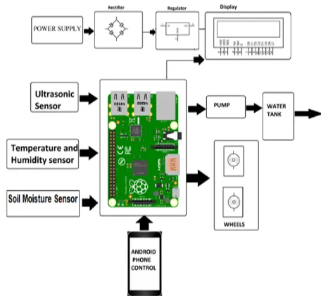
Figure 4. Block Diagram
The images shown above are circuit diagram, circuit implementation and the block diagram of the prototype.
A. Sensor
Types of sensors used for implementation:
1) Ultrasonic Sensor (HC-SR04)
The range of this sensor is 3cm - 3m, with a requirement of 5V DC power supply. The Resolution is 1cm and the Ultrasonic Frequency 40Khz. This sensor is used for obstacle detection, as soon as it detects an obstacle a buzzer starts buzzing and the robot stops instantly to avoid any kind of collision.
[image:2.595.51.288.551.731.2]Figure 5. HC-SR04 ultrasonic sensor
2) Temperature & Humidity Sensor (DHT11)
This sensor operates at 3.3V or 5V DC power supply. The resolution for sensing the temperature and humidity is 8 bits. Measurement range of humidity is 20%-95%RH and 0-50°C for the temperature sensor. This sensor is used to measure the temperature and humidity of the area and collect the data to be analyzed, with all this data further actions are performed
Figure 6. DHT11 sensor
B. Motors
[image:3.595.310.560.99.249.2]The motors have an operating voltage of 3-5V DC. It has a torque of 1.8 Kg-cm the speed of the motors without any load is 0.10 sec/60 Degree. Rotational range is 180 degrees. 4 motors used in this prototype as we are using caterpillar tracks, the purpose of using this motor in the vehicle due to operation in farms where the ground will be uneven so as to not get stuck in the mud.
Figure 7. Caterpillar Tracks
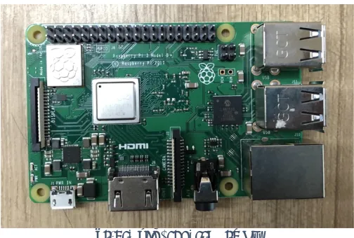
C. Raspberry Pi 3 B+
The CPU has a 1.4Ghz 64-Bit quad core ARM Cortex-A53 CPU, and RAM of 1Gb LPDDR2 SDRAM.
It needs a power of 5V DC to operate, and supports operating systems like Linux and Unix, we can code this processor by python. This microprocessor is used as it has good processing power and memory management, as we have connected so many peripheral and sensors to process all that data is a tedious task for any other processor thus raspberry pi is preferred.
Figure 8. Raspberry Pi 3 B+
D. Bluetooth Module (HC-05)
It has a range of up to 30 feet, and operates at typically 5V DC. It follows IEEE 802.15.1which is a standard protocol and has an operating current of 30mA. It uses frequency hopping spread spectrum.
[image:3.595.308.560.456.626.2] [image:3.595.40.284.456.625.2]Figure 9. HC-05 Bluetooth module
E. L293D
[image:4.595.34.288.99.258.2]It has an operating range of 4.5V to 36V, and it has a high immunity noise. This IC can be used to control various types of motors but in this project, it is used to control the motors of robotic vehicle. As mentioned before the vehicle is quite heavy and has four motors so to evenly distribute the power and properly control the movement of the vehicle using this IC.
Figure 10. L293D Motor Driver
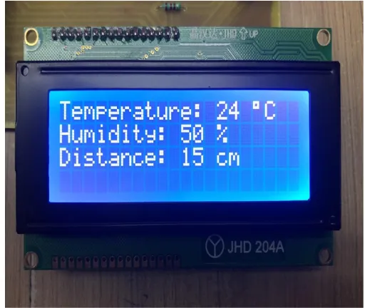
F. LCD Display
[image:4.595.305.561.351.567.2]JHD204A LCD is used to display the necessary data collected by the sensors on the robotic vehicle, this LCD has display of 20 CHAR x 4 ROWS. It has an operating voltage of 5V DC.
Figure 11. Start-up Message
Figure 12. Data Representation
G. IOT Webpage
Gecko platform is used as an efficient GUI builder and it has a two-way communication. It supports API over different microcontrollers.
[image:4.595.27.287.432.625.2]Figure 13. IOT Gecko webpage (Pump Off)
Figure 14. IOT Gecko webpage (Pump On)
H. Android Controller
To control the vehicle an app called as Bluebot is used. This app controls all the movements of the robot-like forward/backward and left/right, one other important function of this app is that key A is used to turn on/off the pump of the tank for spraying of water.
Figure 15. Bluebot Android Controller
4.SYSTEM DESCRIPTION
The sensors, camera and the water tank are mounted on the vehicle, which will be used to analyze and monitor a given region and spray water wherever and whenever necessary. The camera provides a live feed of the surrounding which can be monitored using a cellular device. The sensors will be used to collect the temperature and humidity readings along with obstacle detection. All the data collected from the sensors will be transmitted to an IoT webpage through Wi-Fi.
The IoT web page also shows an alert message if any obstacle is detected by the rover and can be accessed from any place using the correct credentials. From the data amassed, it can be assessed whether the field needs to be irrigated or not. The system can be accessed from far-off, due to the usage of Wi-Fi. The vehicle is controlled via the Bluetooth module which is connected to an android phone. An application called Bluebot is used which controls the movement of the vehicle and spraying of the water.
During the testing and debugging phase of the project, certain drawbacks and limitations were realized. They are as follows:
• There is a delay of about 5-7 seconds due to the complexity of system
• There is no back visibility as the camera is mounted on the front side of the rover
• Range of the Bluetooth module is limited due to Line of Sight (LoS).
5.CONCLUSIONANDFUTUREWORK
The design and implementation of automated irrigation system is developed using Raspberry Pi microcontroller. The system is cheap and is easy to carry from one place to another limitation of the hardware being associated with a system has been reduced to a great extent. As an end thought, the system will allow the user to control it in a way that reduces the gap between the physical world and the digital world with an output more intuitive.
FUTURE SCOPE
[1] Nikesh Gondchawar, Prof. Dr. R. S. Kawitkar, “IoT based Smart Agriculture” International Journal of Advanced Research in Computer and Communication Engineering Vol. 5, Issue 6, June 2016
[2] Kishor Kumar R, Manjunath B Kajjidoni and Pradeep Kumar M S, “Smart Agriculture System Using IoT” Proc. of the Int. Conf. on Current Trends in Eng., Science and Technology, ICCTEST
[3] Shweta B. Saraf, Dhanashri H. Gawali, “IoT Based Smart Irrigation Monitoring And Controlling System” 2017 2nd IEEE International Conference On Recent Trends in Electronics Information & Communication Technology (RTEICT), May 19-20, 2017, India
[4] Vaishali S, Suraj S, Vignesh G, Dhivya S and Udhayakumar S, “Mobile Integrated Smart Irrigation Management and Monitoring System Using IOT” International Conference on Communication and Signal Processing, April 6-8, 2017, India
[5] S.N. Ishak, N.N.N.Abd Malik, N.M. Abdul Latiff, N. Effiyana Ghazali and M. A. Baharudin, “Smart Home Garden Irrigation System Using Raspberry Pi” 2017 IEEE 13th Malaysia International Conference on Communications (MICC), 28-30 Nov. 2017, The Puteri Pacific, Johor Bahru, Malaysia
[6] G. Naveen Balaji, V. Nandhini, S. Mithra, N. Priya and R. Naveena, “IOT Based Smart Crop Monitoring in Farm Land” Imperial Journal of Interdisciplinary Research (IJIR) Peer Reviewed – International Journal Vol-4, Issue-1, 2018 (IJIR) ISSN: 2454-1362
[7] Tanmay Baranwal, Nitika and Pushpendra Kumar Pateriya, “Development of IoT based Smart Security and Monitoring Devices for Agriculture” 2016 6th International Conference - Cloud System and Big Data Engineering (Confluence)
[8] Md Ashifuddin Mondal and Zeenat Rehena, “IoT Based Intelligent Agriculture Field Monitoring System” 2018 8th International Conference on Cloud Computing, Data Science & Engineering (Confluence)
[9] Prof. K. A. Patil and Prof. N. R. Kale, “A Model for Smart Agriculture Using IoT” 2016 International Conference on Global Trends in Signal Processing, Information Computing and Communication