Study of Non-Linear FE Vehicle Model using Multiple Impact Simulation
Nehal Kulkarni
1, Prof. S.S. Chappar
21
PG student, Department of Mechanical Engineering, BLDEA’s V P Dr. P G H CET VIJAYAPURA, KARNATAKA, INDIA.
2
Professor, Department of Mechanical Engineering, BLDEA’s V P Dr. P G H CET VIJAYAPURA, KARNATAKA, INDIA.
---***---Abstract: The simulation of vehicle crashes by using
computer software has become an indispensable tool for shortening automobile development time and lowering costs. It also has huge impact on the crashworthiness of an automobile. Automobile CAE Software is mainly used to assess the performance quality of vehicles. As the automobile is a product of technology -intensive complexity, its design analysis involves a broad range of CAE simulation technique. An integrate CAE solution of automobiles can include comfort analysis (vibration and noise analysis), safety analysis (car body collision analysis), process-cycle analysis, structural analysis, fatigue analysis, fluid dynamics analysis, test analysis, material data information system and system integration. The objective of this work is to simulate a A-pillar, B-pillar, of crash of an automobile vehicle and validate the results. The aim is also to alter some of the materials of the components with a view to reduce the forces experienced during the crash. Computer models were used to test the crash characteristics of the vehicle in the crash. The software used for the simulation will be LS-DYNA. It is widely used by the automotive industry to analyze vehicle designs. It accurately predicts a car's behavior in a collision.
Keywords: Crashworthiness, LS-dyna, A & B Pillars, CATIA, Load curves, Deflections and Von Misses stresses.
1.INTRODUCTION
First ever accident in the field of automotive sector has took place in the city of New York in 1889.This situation raised the birth of automobile protection as one of the research areas of interest. From past three decades, occupant protection is considered as the important design criteria among all the functional performance for motor transportation on ground. Industry people understood the need in the beginning stage to carry out protection of motor passenger before everyone thought about automobile plays vital role for means of transportation.
In year 1934 General Motors conducted first ever motor-to-object frontal crash test, lapping the motor into a still wall. These first tests were considered most important in today standards.
1.1
INTRODUCTION TO A-PILLAR:
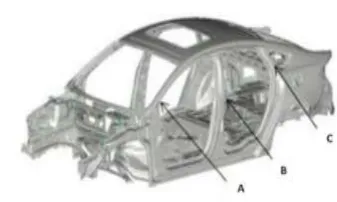
Pillars nothing but the vertical or marginal vertical structural supports of a motor body area named respectively by the names A, B, C and D pillar (in large car) checking from all the structural parts front to back. Better understanding in the car’s pillars is understood by alphabetical designation which
gives us common platform for design and vital communication.
An ideal A-pillar is one that is light and slim and remains folded during normal operation but expand by high-pressure gas in a crash, resulting in a significant increase in cross-section, strength and high crush resistance. These contradictory requirements can be combined within A-pillar for bloomed section. Like common driving, the cross-sectional area of specimen considered is folded form, which helps in providing good visibility for driver. First in the form of crash, the A-pillar blooms, which gives a vital raise in cross-sectional area, and the higher cross-sectional area raises the pillar strength. Additional strength of the A-pillar can be obtained by maintaining the pressure inside the A-pillar during loading. Expandable A-pillars may be accomplished in folding its body structure, and when needed, expanding the structure by giving rise to a higher internal pressure. A cost cum weight and efficiency way for generating overpressure was in using pyrotechnical inflators (gas generators).
1.2
B-PILLAR
side accidents of motor vehicles. The positional structures of B-pillars in motor vehicle considers it very much importance in the provisions of high sudden crash resistance and safety to motor vehicle passengers in sudden crash programmers that involves sudden side impacts. The highest stress given by higher sudden crash structural members (like B-Pillars) after displacement is of much importance, as it can help in predicting whether the specimen has over esteemed its yield criteria or not. These types are likely achieved by considering side pole side sudden crash test (known as Advanced Euro Mobile Deformable Barrier-AEMDB) or computerized test. However, reinforcing and strength forming structures and its members are most advantageous as compared to substitution with new are again designed members as insufficient resistance for external loading will be achieved.
Fig 1.2 Typical frame of car with B-pillars
1.3
Crashworthiness:
It is the ability of a structure to protect its occupants during an impact. This is commonly tested when investigating the safety of vehicles. Depending on the nature of the impact and the vehicle involved, different criteria are used to determine the crashworthiness of the structure. Crashworthiness may be assessed either prospectively, using computer models (e.g., LS-DYNA, PAM-CRASH) or experiments, or retrospectively by analyzing crash outcomes.
Crash test is a form of destructive testing usually performed in order to ensure safe design standards in crashworthiness and crash compatibility for various modes of transportation or related systems and components. Frontal-sudden crash tests: is the one which all or most of people initially think when thinks for a vehicular crash analysis. Motor Vehicles usually subjected sudden crash for solid objects or concrete walls with pre-defined speed, but there are also be vehicular impacting vehicle crash.
Roll-over analysis: is one type of tests where vehicular ability (especially the pillars attached to roofs) in supporting itself for dynamic conditions. much recently, dynamic rollover analysis was proposed in line with static crush analysis.
Automotive safety: reduction in the relative velocities between the passengers and the vehicular interiors to reduce risking of injuries to the passengers during accidents.
Fig 1.3 Typical supporting pillars and their location
2. RESEARCH METHODOLOGY
The finite element (FE) method is employed to conduct the study for this project work. The software used is LS-DYNA. LS-DYNA is predominant software in the field of FEA. This project needs nonlinear large deflection analysis, for which LS-DYNA solver is known to yield accurate results.
2.1 MATERIAL PROPERTIES
In many of the FEA software it is possible to use multiple materials within the structure like Isotropic (in which material property remains same throughout), Orthotropic and An-isotropic materials. The above layered model created was imported to LS-DYNA workbench through IGES or STEP file and the material model is created using the standard vehicle engine data. The Material properties considered for the Present study are the present industrial Properties and this study gives the need of the hour. The investigation of linear and nonlinear performance was done with materials, like Steel. The material properties used in the analysis are tabulated as Table 2.1
SL.NO NAME THICKNESS
YOUNGS MODULUS
(E)
DENSITY
(ρ)
1. A pillar 1.4 210000 5.89E-09
2. A pillar 2 210000 6.29E-09
3. upper a pillar trim 2.8 1100 2.20E-09
4. up a pillar trim rein for 0.9 217000 4.48E-09
5. door 1.4 211000 7.89E-09
6. door window sill 1.4 216100 7.89E-09
7. door up reinforce 0.51 214800 4.48E-09
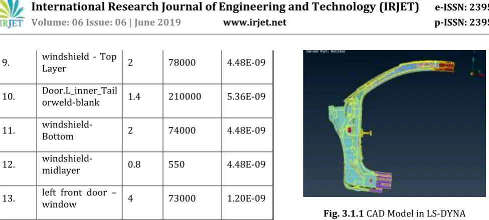
[image:2.595.80.259.305.377.2]9. windshield - Top Layer 2 78000 4.48E-09
10. Door.L_inner_Tailorweld-blank 1.4 210000 5.36E-09
11. windshield-Bottom 2 74000 4.48E-09
12. windshield-midlayer 0.8 550 4.48E-09
13. left front door – window 4 73000 1.20E-09
Table 2.1:Industrial Propertis of the Pillars
3. LS-DYNA Nonlinear Analysis
The methodology adopted for conducting nonlinear analysis of 13layered A-pillar and B-pillar Materials. Details of the project are given as below.
3.1 Modeling of A-pillar
We require solid model of A-pillar of vehicle to build FE model. here we have taken real engine for our study first we got the dimensions of real engine which is retrieved by CMM machine, using those dimensions we modeled A-pillar in modeling software called CATIA V5. And those are assembled in assembly work bench of CATIA modeling software. Fig. below shows the CAD Model of the A-pillar. The representative model layered shells were modeled in CATIA V5. A stacking sequence was used for modeling layered structure of steel shells.
Creating part (solid) modeling of each part & Assembling.
[image:3.595.40.528.49.269.2] Converting solid model into IGES format.
Fig 3.1 Compact view the CAD model of the A-pillar
Full detailed view of A-pillar imported on to LS-DYNA is shown with color contours.
Fig. 3.1.1 CAD Model in LS-DYNA
3.2 Meshing of A-pillar
The meshing of the A-pillar structure is carried out by considering SHELL281which has the special advantages list of advantages of SHELL 281 are as below,
It is a 4-node element with six degree of freedom at each node.
It facilitates modeling of layered steel structures. It has elasticity, plasticity, stress stiffening, large
strain and deflection, and nonlinear Stabilization features suitable for nonlinear analysis of thin steel. It is best suitable for layered and structured shells. It is suitable for linear and non-linear thin to
moderately thick shells.
[image:3.595.329.538.496.662.2]Therefore, steel metal and thin steel were meshed with SHELL 281 elements.
Fig. 3.2 Meshed FE Model of A-pillar
3.3 Modeling of B-pillar
[image:3.595.66.253.524.686.2]Fig. 3.3.1 Compact view the CAD model of the B-pillar
[image:4.595.340.527.176.340.2]Full detailed view of B-pillar imported on to LS-DYNA is shown with color contours.
Fig. 3.3.2 CAD Model in LS-DYNA
3.4 Meshing of B-pillar
The meshing of the B-pillar structures is also carried out by considering SHELL 281, the model was meshed using sweep mesh technique, which holds good for axisymmetric bodies. The parameters which signify the quality of the mesh such as, aspect ratio, warpage, skew angle, Jacobean, minimum and maximum angle were satisfied. A layered element was necessary to model the composite structures, hence SHELL281 quadratic element was used.
3.5 Loading and boundary conditions
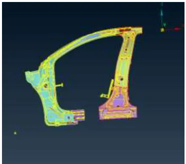
[image:4.595.75.251.309.458.2]In this stage for defining boundary conditions LS-DYNA to best simulate the experimental testing conditions, the models were constrained in both the ends respectively. Detailed fig. is shown below,
Fig 3.4 Detailed view of A & B pillar
4. FEA RESULTS AND DISCUSSIONS
The below fig shows the imported 3D A-pillar of vehicle. The various stress & deformation contours on the A-pillar and stress and directional deformation (along the x-axis) for a velocity of 29kmh are represented below, which is considered as standard speed for the assessment of crashworthiness according to NCAP (New Car Assessment Program) for the HIC (Head Injury Criteria) for the person driving the vehicle. This speed will indicate the minimum amount of injury that person can undergo during the crash analysis.
[image:4.595.335.462.516.673.2] [image:4.595.60.260.616.751.2]Fig.4.1.1 Stress counters of A-pillar
It is observed for the A-pillar maximum displacement is observed in the vicinity side point as shown in the Fig 4.1 and the maximum displacement is observed to be 24.15mmThe maximum stress is observed to be 6.28e -2GPaand it is clear from the Fig 4.1.1 that maximum deformation is observed corresponding to maximum stress region.
The below fig. shows the imported 3D B-pillar of vehicle. The various stress & deformation contours on the A-pillar and stress and directional deformation (along the x-axis) for a velocity of 35kmh are represented below,
Fig.4.1.2 Displacement contour of B- Pillar
Fig.4.1.3 Stress contours of B- Pillar
It is observed for the B-pillar maximum displacement is observed in the vicinity side point as shown in the Fig 4.1.2 and the maximum displacement is observed to be 50.61mm. The maximum stress is observed to be 8.53GPa and it is clear from the Fig 4.1.2 that maximum deformation is observed corresponding to maximum stress region.
From the above study it is clear that the occupant sitting inside the vehicle will have serious injury because of the B-pillar, rather than the A-B-pillar, as the study shows the displacement of B-pillar is higher compared to the displacement of A-pillar and even the stress induced are also higher so this comparative study will definitely give us clue understand the vehicle crashworthiness for the side crashes.
5. CONCLUSIONS
The conclusions derived based on the FEA numerical analyses on A & B-pillars are presented as follows.
LS-DYNA FE Analysis overestimated the other commercial software packages under NCAP (New Car Assessment Program) test. Hence a nonlinear buckling analysis is mandatory.
LS-DYNA Non-linear analysis predicts the realistic value as compared to other tests.
The performance in the dummies (occupant) which are verified at a greater impact speeds of 35mph. Enhances injury criteria under NCAP.
This vehicle crashworthiness evaluation under side impact gives us real picture of amount of injury in head of person sitting inside the vehicle.
REFERENCES
[1] TejasagarAmbati, ‘SIMULATION OF VEHICULAR
FRONTAL CRASH-TEST’, SAE International, 2007-01-1245, 2017.
[2] P. Satope. I. B. Owunnat, Design optimization of a
B-pillar for crashworthiness of vehicle side impact. Journal of Mechanical Engineering and Sciences, Volume 11, Issue 2, pp. 2693-2710, June 2017.
[3] Shaik K b, OPTIMIZATION OF A AND B PILLARS OF
AUTOMOBILE FOR CRASH WORTHINESS- Journal of Advanced Research in Dynamical and Control Systems, Vol. 9. Sp– 14 / 2017.
[4] Jian LIU and Tao SUN “Numerical Simulation of Car
Crash Analysis Based on Distributed Computational Environment ProcInstnMechEngrs (IMECHE) Part K.2004, pp 107-117.
[5] Byeong Sam Kim, ‘FINITE ELEEMNT FRONTAL CRASH
ANALYSIS OF NEV VEHICLE’S PLATFORM WITH UPPER AND SUB FRAME BODY’, journal Iternational,2005-26-046, 2009.
[6] BerukHailu, ‘A New Accident Proof Material Design for B
- Pillar of A Car’ International Journal of ChemTech Research, Vol.11 No.07, pp 01-11, 2018.
[7] AniekanEssienubongIkpe, Design and Reinforcement of
a B-Pillar for Occupants Safety in Conventional Vehicle Applications, International Journal of Mathematical, Engineering and Management Sciences, Vol. 2, No. 1, 37– 52, 2017.
[8] Dongming Sun, Lightweight Study of Carbon Fiber
Composite B-Pillar Based on Equal Stiffness Principle- Open Access Library Journal, 2018, Volume 5, e4822.
[9] BengtPipkorn, Improved car occupant safety by
expandable Apillars. International Journal of Crashworthiness, ISSN: 1358-8265.
[10] M.M.Kamal, “Analysis and Simulation of Vehicle to
Barrier Impact,” SAE Paper No. 700414.
[11] C.L.Magee - Keynote Address, “Design for Crash Energy
Management - Present and Future Developments,” The Seventh International Conference on Vehicle Structural Mechanics.
[12] Wierzbicki, T,. and W. Abramowicz, “Stability of
Progressive Collapse,” Manual of Crashworthiness Engineering, Vol. III, Center For Transportation Studies, Massachusetts Institute of Technology.
[13] L.M.Patric, “Human Tolerance to Impact and Its
AUTHOR PROFILE
NEHAL ASHOK KULKARNI