warwick.ac.uk/lib-publications
A Thesis Submitted for the Degree of PhD at the University of Warwick
Permanent WRAP URL:
http://wrap.warwick.ac.uk/103098
Copyright and reuse:
This thesis is made available online and is protected by original copyright. Please scroll down to view the document itself.
Please refer to the repository record for this item for information to help you to cite it. Our policy information is available from the repository home page.
Towards a cell-based chemo receiver for
artificial insect olfaction
By
SANJU THOMAS
School of Engineering
UNIVERSITY OF WARWICK
A thesis submitted to the University of Warwick
for the degree of Doctor of Philosophy
ii
Table of Contents
Dedication i
Table of Contents ii
List of Figures vii
List of Tables xiii
Acknowledgment xiv
Declaration xv
List of Author Publications xvi
Abstract xviii
List of Abbreviations xix
1.1 Insect-Inspired Communication System 2
1.2 Mechanism of insect olfaction 3
1.3 Piezoelectric microsensors as chemical sensors 6
1.3.1 SAWR micro sensors 8
1.3.2 FBAR micro sensors 9
1.4 Electronic noses, tongues and their applications 11
1.5 Research objectives 12
1.6 Outline of the thesis 13
2.1 Introduction 15
2.2 Historical background of acoustic waves 16
2.2.1 Piezoelectric Effect 17
2.2.2 Applications of piezoelectricity 18
2.2.3 Inter-digital Transducers 18
2.3 Fundamental Physics of Acoustic Waves 19
2.3.1 Acoustic waves in an elastic medium 19
2.3.2 Piezoelectric Interactions 22
2.3.3 Acoustic Wave Damping 23
2.4 Acoustic Waves: Classification 25
2.4.1 Bulk acoustic waves 27
iii
2.4.1.2 Thickness Shear Mode 29
2.4.2 Surface Acoustic Waves 31
2.4.2.1 Rayleigh SAW waves 32
2.4.2.2 Shear-horizontal surface acoustic waves 35
2.4.2.3 Love waves 37
2.4.2.4 Flexural Plate Waves 39
2.5 SAW substrate materials 40
2.6 Practical design aspects of SAW devices 42
2.6.1 SAW Delay line 43
2.6.2 SAW resonator configuration 44
2.7 Detection mechanisms of AW sensors 45
2.7.1 Mass Loading 46
2.7.2 Mechanical properties 47
2.7.3 Electrical properties 49
2.7.4 Thermal effects 50
2.8 Summary 50
3.1 Introduction 52
3.2 Acoustic Wave Perturbation 53
3.3 Perturbation mechanisms for R-SAW Devices 55
3.3.1 Mass Loading 55
3.3.2 Acoustoelectric Response 56
3.3.3 SAW Response from elastic and viscoelastic films 58
3.3.3.1 Acoustically thin films 59
3.3.3.2 Acoustically thick films 59
3.4 Perturbation mechanisms for SH-SAW Devices 60
3.4.1 Mechanical Perturbations 62
3.4.1.1 Mass Loading in Liquid 63
3.4.1.2 Viscous Coupling 63
3.4.2 Acousto-electric interactions 63
3.5 External environment effects 65
3.5.1 Temperature effects 65
3.6 Generalised perturbation model for SAW device 66
3.7 SAW sensor design 67
3.7.1 Interdigital Transducer Design 67
iv
3.7.3 Design parameters 72
3.7.4 SH-SAW Sensors: Design and layout 73
3.7.5 R-SAW Sensors: Design and layout 76
3.8 RF characterisation of sensor devices 77
3.8.1 Transmission characteristics of SH-SAW sensors 79
3.8.2 Transmission characteristics of R-SAW sensors 82
3.9 SAWR Oscillator circuit design and implementation 83
3.9.1 SAW sensor board 85
3.9.2 Oscillator board 85
3.9.3 Filter board 85
3.10 Summary 86
4.1 Introduction 88
4.2 SAWR Sensor Array 91
4.3 Ratiometric Infochemical Communication 92
4.3.1 Experimental System Setup 92
4.3.2 Polymer selection and Coating 94
4.3.3 Feasibility study using fruit volatiles 98
4.3.4 Polymer-SAWR Responses 100
4.3.1 Ratiometric signal generation 102
4.4 SAWR Response Repeatability 103
4.5 Ratiometric decoding 105
4.6 Summary 110
5.1 Introduction 111
5.2 Cell-based SH-SAWR Biosensor 113
5.2.1 Dual Biosensor System 116
5.3 Insect cell-based expression system 117
5.4 Microfluidic system setup 118
5.4.1 Microfluidic chamber design 118
5.4.2 Experimental Setup 119
5.4.3 Cell culture, transfection and calcium assay 120
5.5 Measurement Protocol 121
5.6 Monitoring Sf9 cell deposition and attachment 122
v
5.6.2 SAWR response to Sf9 cell adhesion 125
5.7 Endogenous receptors in wild Sf9 cells 127
5.7.1 Response due to free SAWR biosensor system 127
5.7.2 Response due to shorted SAWR biosensor system 129
5.7.3 Ionomycin response on SAWR biosensor system 130
5.8 Heterologous expression of olfactory receptor proteins 131
5.9 SAW sensor response to transfected Sf9 cell layer 131
5.9.1 Ligand elicited response of olfactory receptors 132
5.9.2 Ionomycin response of olfactory receptors 134
5.10 Functional assay of ORs in Sf9 cells using calcium imaging 136
5.11 Result Discussion 138
5.12 Summary 140
6.1 Introduction 142
6.2 Sensor System Design 143
6.3 SMR as a tuning element 144
6.4 Oscillation conditions 146
6.5 Discrete Oscillator and interface circuitry 148
6.6 Pierce FBAR Oscillator 149
6.6.1 CMOS Oscillator Designs 151
6.7 Mixer Input Baluns 156
6.8 Down-conversion Mixer circuitry 158
6.9 Associated drive circuitry 162
6.10 Post-fabrication results 164
6.10.1 Output spectrum of FBAR-CMOS oscillators 164
6.10.2 Comparator differential output 165
6.11 Phase noise Analysis of CMOS-FBAR Oscillator 166
6.12 Complete ASIC design 168
6.13 Application of MEMS-FBAR Sensor System 169
6.13.1 Particulate Matter Detection 169
6.14 Hybrid CMOS-MEMS integration 172
6.15 VLSI Integration of Acoustic Sensor System 173
6.16 Design limitations and future work 174
vi
7.1 Summary of contributions 176
7.2 Future Work 178
7.2.1 Ultrafine Particle Sensing 178
7.2.2 Liquid phase detection with different cell types 178
vii
List of Figures
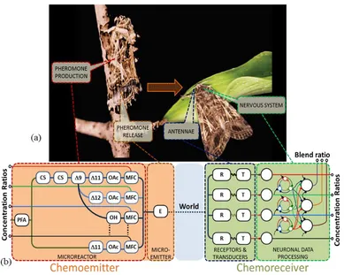
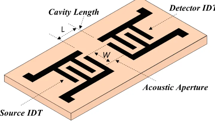
Figure 1.1. (a) A schematic diagram showing the relation between the primary biological components of the pheromone-based insect communication (b) Corresponding bio-inspired modules that form a possible configuration of a biosynthetic infochemical communication system with
a chemoemitter and chemoreceiver. ... 3
Figure 1.2. The proposed mechanism of olfactory receptor signal transduction. ... 6
Figure 1.3. The schematic of a cell-coated SAW biosensor ... 8
Figure 1.4. The schematic of an FBAR-SMR sensor ... 10
Figure 2.1. Conversion of mechanical energy into electrical energy by piezoelectric effect ... 17
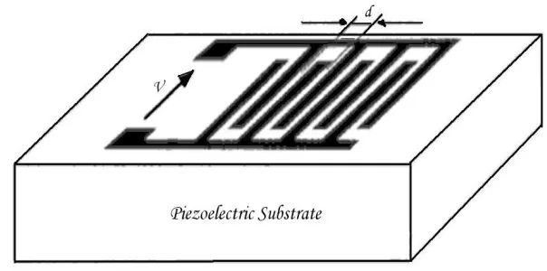
Figure 2.2. Basic IDT structure in a piezoelectric crystal ... 19
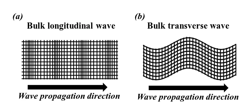
Figure 2.3. Schematic of different types of elastic waves in unbounded solids. (a) Longitudinal wave (b) Transverse wave ... 20
Figure 2.4. Pictorial representation of longitudinal wave showing the particle displacement direction with respect to the direction of wave propagation ... 26
Figure 2.5. Pictorial representation of shear wave showing the particle displacement direction with respect to the direction of wave propagation. ... 26
Figure 2.6. Shear horizontal Acoustic Plate mode (SH-APM) device. Adapted from [69]. ... 29
Figure 2.7. Thickness Shear Mode resonator device: (a) top view (b) cross-sectional view illustrating the direction of the shear wave displacement... 31
Figure 2.8. Rayleigh wave propagation showing the surface deformation profile and the particle displacement direction. ... 32
Figure 2.9. Co-ordinate system showing the propagation vector for SAWs. ... 33
Figure 2.10 Rayleigh wave particle displacements on sagittal plane ... 35
Figure 2.11 Shear Horizontal Surface Acoustic Wave propagation. ... 36
Figure 2.12. STW propagation employing an energy trapping grating between IDTs ... 37
Figure 2.13 Love wave propagation. ... 38
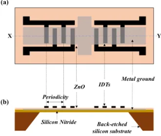
Figure 2.14. Schematic of a typical flexural plate wave device (a) Top view of the chip (b) Cross-sectional view along X-Y line. ... 40
Figure 2.15. SAW delay line device with IDTs metallised onto the top of the substrate ... 43
Figure 2.16. Schematic layout of surface acoustic wave based resonator (a) One port SAW resonator (b) Two port SAW resonator ... 45
viii
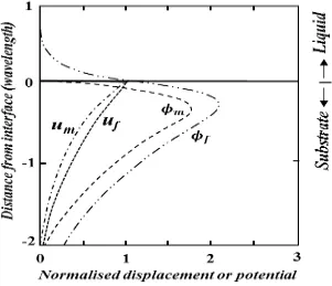
Figure 3.2. Normalized SH-SAW particle displacement (u) and potential ()
profiles at the crystal/water interface for metalized (m) and metal free surface (f). Adapted from [76], [98] ... 61 Figure 3.3. Characteristic features of (a) solid finger IDT (b) Split finger IDT ... 68 Figure 3.4. (a) Maximised SAW reflections for a solid finger IDT. (b) Minimal SAW reflections in the case of a split finger-pair IDT ... 70 Figure 3.5. Types of SAW reflector gratings (a) Shallow grooves etched into piezoelectric substrate (b) Open-circuited metal strips (c) closed circuited metal strips ... 71 Figure 3.6. Optical micrographs of three variations of a 60 MHz LiTaO3 SH-SAW
resonator with (a) metallised sensing surface, (b) free sensor surface .. 75 Figure 3.7. Optical micrograph of a 262 MHz Rayleigh mode dual SAW resonator sensor for gas phase measurements ... 77 Figure 3.8. Signal flow diagram of a two-port network used to define S parameters
ix
Figure 4.3. (a): Prototype of an infochemical test chamber containing syringe pump, micro-evaporator and array of four polymer-coated SAWR sensors. (b): Photograph of the polymer coated SAWR sensor array used inside the test chamber. ... 94 Figure 4.4. Diagram illustrating the partitioning of gas molecules into
SAWR-polymer coating. The ratio of concentrations of analyte in the layer, cp,
and in vapour phase, cv, is called the partition coefficient, K. ... 95
x
Figure 5.5. Various designs of PDMS chambers used to form the microfluidic reservoir. ... 119 Figure 5.6. (a) Photograph showing the dual SAWR sensor inside a PDMS chamber and the associated oscillator circuitry on surface mount printed circuit boards, and (b) the computer-controlled microfluidic cell measurement system with valve and pump control, and interface electronics. ... 120 Figure 5.7. Schematic of the biomimetic antenna realized using SAWR biosensing system with transfected Olfactory Receptors. ... 122 Figure 5.8. Dual Bio-SAW sensor where the sensing device is coated with wild sf9 cells while reference device is left uncoated. ... 123 Figure 5.9. Scanning electron micrograph of Sf9 cells attached to the free surface of the LiTaO3 SH-SAWR sensor. ... 124
Figure 5.10. Sf9 cell adherance to one side of the dual SAWR sensors, showing both free (a) and gold-coated (b) LiTaO3 SAWR surfaces. ... 125 Figure 5.11. Frequency response of a 60 MHz dual shorted SAWR sensor during the deposition and stable attachment of about 35,000 Sf9 cells on the metallized sensing area. ... 127 Figure 5.12. Frequency response of a 60 MHz free dual device to 100 μM octopamine.
xi
xii
xiii
List of Tables
Table 3.1. Acoustoelectric properties of several SAW substrate materials ... 73 Table 3.2. Design parameters for the SH-SAW resonator for cell-based
chemoreceiver ... 74 Table 3.3. Design parameters for the SAW resonator for gas phase detection ... 76 Table 4.1. Ratios of the two pheromones used to demonstrate the basic principle of
xiv
Acknowledgment
First and foremost I thank my God and Saviour Jesus Christ for giving me the ability, strength, motivation and each and everything required to accomplish this great task.
I express my greatest sense of gratitude to my academic supervisor Professor Julian Gardner who has been my beacon light and motivator throughout the metamorphosis of this dissertation. He had confidence in me when I doubted myself, and brought out the good ideas in me. It is my great pleasure to have such a great personality as my guide. I extend my sincere gratitude towards Dr. Marina Cole for her constant help and guidance throughout my project. She deserves many thanks for her continuous support during my study. I would also like to acknowledge the EPSRC for providing me the Doctoral Training Grant during my study.
I would like to thank Dr. Zolton Racz for his advice and support over the course of this research. I am grateful to the staff at the Microelectronic Support Centre, STFC Rutherford Appleton Laboratory for their assistance and support in the design and debugging of the CMOS ASIC chip. I am also grateful to all of my friends and colleagues at the Microsensors and Bioelectronics Laboratory, University of Warwick including Geraint Rhys Jones, Farah H. Villa-López, Tim Vincent, Dr Barbara Urasinska-Wojcik, Dr Guangfen Wei, and my old colleagues including Yang Jian, Dr Prasanta Guha, Dr Shrey Pathak and Dr Foysol Choudhary for their help and stimulating exchanges of ideas. I would particularly like to thank Mr F. T. Courtney and Mr Ian Griffith for all their assistance in the technical matters throughout the duration of my study.
xv
Declaration
The work described in this thesis was conducted by the author according to the
university regulations for the degree of Doctor of Philosophy, except where stated
otherwise, in the School of Engineering, University of Warwick. This thesis has not
been previously submitted in any previous application for any degree. The following
are the list of sections with contributions from partners and collaborators.
Section 3.7: Design of SAW resonators used in this thesis were performed by Shrey Pathak, University of Warwick.
Section 4.3.3: Experiments performed by Jian Yang, University of Warwick.
Chapter 5: Experiments performed at the Department of Cell Physiology and Pharmacology, University of Leicester, UK in collaboration with Dr. Melissa Jordan.
Section 6.3: Design of SMR sensor performed by Farah H. Villa-López, as part of an EU Project ‘Multisensor Platform’. University of Warwick.
Parts of the work have been presented at international conferences and published in
xvi
List of Author Publications
Peer-reviewed Journal articles:
W. Xuan, M. Cole, J. W. Gardner, S. Thomas, X. Wang, S. Dong, and J. Luo, “A film bulk acoustic resonator oscillator based humidity sensor with graphene oxide as the sensitive layer,” J. Micromechanics Microengineering, vol. 27, no. 5, p. 8, 2017.
F. H. Villa-López, G. Rughoobur, S. Thomas, A. J. Flewitt, M. Cole, and J. W.
Gardner, “Design and modelling of solidly mounted resonators for low-cost particle sensing,” Meas. Sci. Technol., vol. 27, no. 2, p. 25101, 2016.
S. Thomas, F. Villa-Lopez, J. Theunis, J. Peters, M. Cole, and J. Gardner, “Particle sensor system using Solidly Mounted Resonators,” IEEE Sens. J., vol. 16, no. 8, pp. 2282–2289, 2015.
S. Thomas, M. Cole, F. V. Lopez and J. W. Gardner. 2015. “High frequency surface acoustic wave resonator-based sensor for particulate matter detection” Sensors and Actuators A: Physical, 244: 138–145. doi:10.1016/j.sna.2016.04.003.
Conference articles:
S. Thomas, F. V. Lopez, J.W. Gardner, M. Cole, J. Peters and J. Theunis, “A low-cost acoustic microsensor based system-in-package for air quality monitoring,” IEEE Sensors Conference 2016, 31 Oct-2 Nov, Orlando, USA.
S. Thomas, M. Cole, A. De Luca, F. Torrisi, A.C. Ferrari, F. Udrea, J.W. Gardner,
“Graphene-coated Rayleigh SAW Resonators for NO2 Detection,” EuroSensors
Conference 2014, September 7-10, Brescia, Italy.
F.H. Villa-Lopez, S. Thomas, W. Ludurczak, M. Cole and J.W. Gardner, “Finite Element Modelling of Particle Sensors based on Solidly Mounted Resonators,” IEEE Sensors Conference 2014, November 2-5, Barcelona, Spain.
xvii
S. Thomas, M. Cole and J.W. Gardner, "Particulate matter detection based on Acoustic Resonators for air-quality monitoring", COST Action TD1105- New Sensing Technologies for Air-Pollution Control and Environmental Sustainability
2nd Scientific Meeting, 18-20 December 2013, Cambridge, UK.
S. Thomas, M. Cole, Z. Rácz, J.W. Gardner, “Dual High-Frequency Surface Acoustic Wave Resonator for Ultrafine Particle Sensing,” The 12th Annual IEEE Conference on Sensors, November 4-6, 2013, Baltimore, USA.
S. Thomas, M. Cole, J.W. Gardner, “High-frequency One-port Colpitts SAW Oscillator for Chemical Sensing,” The 6th International Conference on Advances in Circuits, Electronics and Micro-electronics, August 25-31, 2013, Barcelona,
Spain.
M. Cole, S. Thomas, Z. Rácz, J.W. Gardner, M. Jordan and R.A.J. Challis, “ Cell-based surface acoustic wave sensor with transfected olfactory receptors OR67d and OR22a for a highly specific chemo-receiver,” 22nd Anniversary World Congress on Biosensors, 15-18 May 2012, Cancun, Mexico.
S. Thomas, S.L.T. Leong, Z. Rácz, M. Cole, and J.W. Gardner, “Design and Implementation of a High-Frequency Surface Acoustic Wave Sensor Array for Pheromone Detection in an Insect-inspired Infochemical Communication System,” The 14th International Meeting on Chemical Sensors, May 20- 23, 2012, Nurnberg, Germany.
xviii
Abstract
Infochemical communication is ubiquitous amongst all living organisms, and
particularly important in insects. Because smell being the most common basic means
of chemical communication, infochemical blends must be constantly decoded in order
to proclaim their readiness to mate, to mark out territorial boundaries, to warn off
intruders and predators or, in some cases, to locate food or predators with millisecond
precision. The central challenge of the thesis was to mimic nature in both cellular and
molecular levels on to a technological platform that aids in the development of a new
class of technology employing chemicals alone to communicate over space and time.
This thesis describes a body of work conducted in the development of a miniaturised,
smart and label-free cell-based chemoreceiver for artificial insect olfaction, as part of
the development of a novel biomimetic infochemical communication system. A
surface acoustic wave based microsensor has been utilized to engineer and develop a
chemoreceiver system that mimics the cellular and molecular mechanisms occurring
during infochemical detection and decoding in insects. Successful recovery of
ratiometric information with the aid of polymer-based gas-phase measurements,
established the concept of chemical communication. Thus, small scale,
high-throughput infochemical communication has been realized by a combination of
precise spatiotemporal signal generation using fruit volatiles and insect sex
pheromones with highly sensitive detection and signal processing. This was followed
by the investigation of the feasibility of using the prototype cell-based biosensor
system in a static mode for artificial insect olfaction applications, mimicking the
cellular detection in the receptor/antenna apparatus of insects. Finally, as part of the
development of a compact and low-power portable chemoreceiver system, the discrete
sensor drive and interface circuitry was deployed in an analogue VLSI chip, thereby
overcoming the associated measurement complexity and equipment cost, in addition
xix
List of Abbreviations
Abbreviations
Definition
AlN Aluminium nitride
BAW Bulk acoustic wave
CMOS Complementary metal oxide semiconductor
FBAR Film Bulk acoustic resonator
FPW Flexural plate wave
GHz Giga hertz
HPSW Horizontally polarized shear waves
IC Integrated Circuit
IDT Inter digital transducer
IF Intermediate Frequency
LiNbO3 Lithium Niobate
LiTaO3 Lithium tantalite
LNA Low noise amplifier
LO Local Oscillator
LPF Low pass filter
MEMS Micro electro mechanical systems
MHz Mega hertz
Mo Molybdenum
MOSFET Metal-Oxide-Semiconductor Field-Effect Transistor
NMOS n-channel Metal-Oxide-Semiconductor
PCB Printed circuit board
PDMS Polydimethylsiloxane
PID proportional-integral-derivative
PMOS p-channel Metal-Oxide-Semiconductor
QCM Quartz crystal microbalance
RF Radio frequency
R-SAW Rayleigh surface acoustic wave
SAW Surface acoustic wave
SAWR Surface acoustic wave Resonator
xx
SH-SAW Shear horizontal surface acoustic wave
SiO2 Silicon dioxide
SIP System-in-package
SMR Solidly mounted resonator
SV Shear vertical
TSM Thickness shear mode
ZnO Zinc oxide
1
CHAPTER 1
Introduction
The purpose of this first chapter is to introduce the concept of biosynthetic
infochemical communication systems upon which the work presented in this thesis
has been carried out. This chapter introduces the reader to the field of insect olfaction
and chemical communication, detailing how information is transferred between insect
species with the help of semiochemicals. The chapter also reviews the chemical
sensors based on piezoelectric microsensors and exhibits how Surface Acoustic Wave
Resonator (SAWR) and Film Bulk Acoustic Resonator (FBAR) micro sensors have
been employed in the area along with their different applications. Next, a brief account
of olfactory biosensors (e-tongues) and electronic noses will be given, discussing the
technology, current devices, and their applications. Thereafter the aims and objectives
of this work presented here have been introduced and the chapter concludes by
2
1.1
Insect-Inspired Communication System
The principal objective of the infochemical communication system is to
develop functional equivalents of the cellular, subcellular and molecular machinery
that mimic the pathway between pheromone production and detection in insects. This
will form the foundation of a new branch of information technology employing
chemicals to communicate over space and time. Figure 1.1(a) shows the basic concept
and biological inspiration behind the novel infochemical communication technology.
The pathways between pheromone production, release and detection in an insect,
namely the moth Spodoptera littoralis, served as biological blueprints for the development of the artificial biosynthetic modules of the molecular, subcellular and
cellular machinery to form the first infochemical communication prototype system [1].
The chemoemitter module shown in Figure 1.1(b) biosynthesise the pheromone
components from a common precursor fatty acid (18:CoA) based upon known
enzymatic activity within the exocrine system of the moth including chain shortening,
desaturation, and functional group modification, within a microreactor. The
ratiometric infochemical cues can be programmed through mass flow control and an
almost limitless diversity of ligands could be created based on the hierarchy of
biosynthetic modules. The volatile infochemical blend is released into the external
environment by thermal evaporation. Furthermore, the transmission of time-sensitive
and time-registered information is possible by controlling the volatility of the
ratiometric compounds. Chemoreception is carried out based on the signalling from
transmembrane-domain receptors that are transduced by acousto-electric sensors. The
highly specific signals (blend ratios) are processed in a ratiometric neuronal model
based on the antennal lobe of moth.
The chemoreceiver module shown in Figure 1.1(b) employing acoustic
microsensors, acts as a tuned detector of the emitted volatile chemical mixture capable
3
level, acousto-electric transduction and a data processing architecture. Its operation
simulates the molecular detection in the antennae of insects and the neuromorphic
signal processing in the antennal lobe.
This state-of-the-art modular chemoemitter-receiver arrangement, as a unified
system, is capable of infochemical communication and can serve as the foundation of a new scientific field for labelling, information transmission and biochemical
interfacing with possible applications in automatic identification and data capture,
product labelling, search and rescue, air silent communication, medical diagnosis and
environmental monitoring.
1.2
Mechanism of insect olfaction
Odour information is known to be of vital significance for most animals,
[image:25.595.125.514.70.381.2]4
of conspecific mates, food and oviposition sites, organize colonies and divide labour.
These complex and diverse volatile semiochemicals are detected and identified by the
eusocial insects with the help of extremely sophisticated biological systems called
olfactory receptor neurons, which are embedded in the hair-like chemosensory sensilla
located on the antennae. A synchronous action of the pheromone receptors is essential
for the recognition of a broad range of chemicals, allowing the matching of a diversity
of chemical odorants. The key specificity in the response to pheromone molecules is
due to the specificity of the ligand binding olfactory receptors (ORs) which are
responsible for sensing odour molecules, forming the largest G protein-coupled
receptor (GPCR) family in mammalian animals. The inherent specificity and
sensitivity of ORs makes them major candidates as biological detectors of volatile
ligands, which can mimic the sensitivity and specificity of insect olfaction. Thousands
of distinct odorants can be recognised and discriminated by the olfactory systems with
extreme high sensitivity and specificity through a large family of proteins encoded by
olfactory receptor genes.
Even though precise mechanisms of insect olfactory signal transduction
remain unclear, there is broad consensus that olfactory signalling in all animals uses
canonical G-protein- coupled receptors that activates signal transduction pathways [2].
Insects are equipped with two pairs of olfactory organs, the antennae and maxillary
palps, which are decorated with thousands of olfactory hairs called sensilla, each of
which may house one or more Olfactory Sensory Neurons (OSN). Research in
vertebrate olfactory system has identified that odours stimulate adenylate cyclase
activity [3], [4], which led to the subsequent identification of Gαs protein [5] and later
to the discovery of a distinct variety of genes encrypting seven transmembrane domain
G-protein-coupled odorant receptors [6]. In all animals, these ORs signals the identity
and quantity of the odorant cues by inducing electrical activity in the primary OSN
and encoding information regarding the stimulus that is then relayed to olfactory
processing centres in the brain.
The cellular and molecular machinery for olfactory transduction of odorant
molecules is located in the olfactory receptor neuron dendrite membrane surface
encapsulated in sensilla within sensory hairs [7]. OSN axons in the insect tissue
antennae expressing the same odorant receptor converge through specific glomeruli in
5
Literature contains conflicting models of insect olfactory receptor signal transduction
claiming that insect odorant receptors are G-protein–coupled receptors [9] or
odour-gated ion channels [10]. According to Sato et al. [10], insect ORs form ligand-odour-gated
cation channels that are activated rapidly by odours in the absence of G-protein
signalling. In part agreeing with the above results, Wicher et al. [9] also revealed that
the variable ORx subunit is a G-protein-coupled receptor and that OR83b is a cyclic
nucleotide-gated ion channel.
An odorant-specific receptor protein ORx and the cation channel Or83b that
conducts the cations Na+, K+ and Ca2+ form the insect odorant receptor complex that
is responsible for olfactory signal transduction. When stimulated by an odorant, ORx
activates the channel protein Or83b by triggering two pathways, a fast and short
ionotropic pathway and a slow and long-lasting metabotropic pathway. A fast and
transient ion conductance is initiated by the direct activation of Or83b by ORx. The
metabotropic pathway involves the activation of Gs protein by ORx. The Gs subunit
in turn stimulates adenylyl cyclase activity, thereby increasing the production of
intracellular cAMP from ATP, which in turn slowly activates a prolonged
non-selective cation conductance through the Or83b. Opening of the Or83b channel
permits Na+ and Ca2+ (mostly Ca2+) influx resulting in membrane depolarization.
Rapid recognition of high odour concentrations is ensured by the ionotropic pathway
while the metabotropic pathway allows highly sensitive odour detection with the help
of Gs subunit. The Figure 1.2 shows the schematic model of insect OR signal
transduction in which an odorant-specific receptor ORx is a G-protein coupled
receptor responsible for metabotropic pathway and OR83b is a cyclic nucleotide-gated
6
1.3
Piezoelectric microsensors as chemical sensors
In process analytical technology, novel chemical sensors and micro sensors are
being developed to quantify a variety of biological processes including gas and vapour
detection as well as sensing species in liquids or solutions. The selectivity of these
chemical sensors are enhanced by the unique application of selective coatings, such as
polymers or enzymes or living cells, used to detect or monitor analytes. Sensors of this
type include those of the piezoelectric nature including FBARs, SAWRs, Quartz
Crystal Microbalance (QCM) and also those of solid-state origin including
ChemFETs, Schottky diodes and chemiresistors [13]. Amongst the various types of
sensors available, piezoelectric devices such as surface acoustic wave (SAW) devices
(Rayleigh surface acoustic wave (R-SAW), Shear Horizontal surface acoustic wave
(SH-SAW), and Flexural Plate Wave (FPW)) [14]–[20] and bulk acoustic wave
devices (QCM, Shear Horizontal Acoustic Plate Mode (SH-APM), FBAR) [21]–[24]
have been used extensively [25], as they exhibit high sensitivity in mass deposition
[26], in addition to the advantages including versatility and reliability [27].
Piezoelectric acoustic sensors provide a direct transduction mechanism to
convert the measured physical parameter that is in the form of mechanical strain, into
electrical charge variations. Most acoustic wave resonators can be used as sensors, as
they are sensitive to mechanical, chemical, or electrical perturbations occurring on the
device surface [28]. They can detect not only mass/density changes, but also viscosity Figure 1.2. The proposed mechanism of olfactory receptor signal transduction.
7
and/or viscoelastic changes [29]–[31], elastic modulus, conductivity and dielectric
properties and have been widely used for applications like monitoring of pressure,
moisture, temperature, force, acceleration, shock, viscosity, flow, pH levels, ionic
contaminants, odour, radiation and electric fields [27], [32], [33]. Acoustic devices
have been found to function efficiently to monitor acousto-electric interactions at the
solid-liquid interface where the device surface has been derivatised with specific
ligands capable of binding species from solution [34], thus forming a highly sensitive
biological sensor. As a result, acoustic wave based biosensors have also been
extensively used to detect the traces of biomolecules [35]–[39] such as DNA, proteins
(enzymes, antibodies, and receptors), cells and tissue (microorganisms, animal and
plant cells, cancer cells etc.), biochemical substances or viruses [27].
The quartz crystal microbalance (QCM) which can operate in fluids, offers the
possibility to successfully characterize biomolecular systems in their natural aqueous
environment [40]. Recent research has shown that QCMs can be used as an electronic
nose [41] and as an affinity immunosensor [42]. QCM based biosensor systems have
become a suitable tool for in situ measurements in biofluids, particularly, for on-line
detection of immunological reactions [43], [44], for surface bioelectrochemistry of
redox enzymes [45], adsorption of proteins, and adhesion of vesicles and living cell
[26], [46]–[49]. Even though QCMs were the first and the most commonly employed
piezoelectric devices especially for biosensing applications, a major drawback is the
lack of selectivity since there is no discrimination between the source of the mass
changes [25]. In addition, other complications related to QCM biosensors include
reduced mass detection limit due to the low operating frequency (range of 5–30MHz),
large base-mass due to a thick substrate (0.5–1mm) and large surface area (>1cm2)
which is not easily scalable, resulting in increased cost of fabrication [27]. However,
SAW devices and the recently emerged FBAR devices proved to have higher
efficiency than their QCM counterpart, as their active layer is about one order of
magnitude smaller than that of the QCM, which allows them to operate at higher
8
1.3.1 SAWR micro sensors
Initially, surface acoustic wave devices found their applications in electronics
and communications industry where they were used as filters and resonators. Lately,
they have called the attention of the scientific researchers in biosensing applications
[50]. Confinement of acoustic energy in their surface layer of about one wavelength
[27], allowed the SAW devices to operate at higher frequencies and hence higher
sensitivities than typical QCM biosensors. The surface acoustic wave is generated by
the centrally placed inter-digital transducers (IDTs) and reflected by reflector strips
fabricated on both sides of the IDTs, and create a standing wave pattern with a distinct
resonant peak, thereby reducing the acoustic losses of the device. Figure 1.3 shows the
schematic representation of a SAW biosensor functionalised with cells. Selective
binding of ligands with the biomarker molecules generate mass change in the path of
the travelling wave, resulting in velocity change of the acoustic wave and consequently
shifts the SAW resonant frequency. Thus, the resulting perturbation in the acoustic
wave propagation on the surface of a piezoelectric crystal is mainly caused by the
mechanical parameters of the layer, electrical parameters and the associated
atmospheric parameters.
In general, the frequency response of a SAW resonator depends upon the mass
density , viscosity , conductivity , and dielectric permittivity , of the medium in
addition to the temperature, pressure and humidity variations [51]. Hence a change in
the frequency can be associated with one of these dependent variables. A dual SAWR
sensor arrangement [52] produces a differential frequency output, ameliorating the
common mode variations including atmospheric changes like temperature, pressure
9
of the measured signal frequency from the MHz range to kHz range, which is of
essential importance from the view point of removing high frequency noise from the
system. Resonant Rayleigh SAW-based sensors, have been used to detect chemical
and biological molecules such as volatile organic compounds (VOCs) [47], CO2 [48],
humidity [48], ammonia [49], biomolecules such as proteins, DNA, drugs [35], [50]–
[52] and pathogens [53]. Rayleigh SAW devices function well in gaseous or vacuum
environments. However, when integrated in microfluidic systems, significant acoustic
energy gets dissipated into the liquid causing significant attenuation and hence poor
sensitivity and noise which impedes them from liquid sensing applications. Hence,
shear-horizontal (SH)-SAW resonators benefitting from transverse displacements
polarized parallel to the surface, have the advantage of lower energy loss in liquids
[54]. The first SH SAW immunosensor based on LiTaO3 was presented by Rapp et al.
in 1993 [55]. Similar to SH-SAW resonators, thickness shear resonators (TSRs),
Flexural Plate Wave, shear horizontal Acoustic Plate Mode (SH-APM) and
STW-based sensors have also demonstrated better mass sensitivity in liquid biosensing
applications where traditional Rayleigh SAW sensors are inappropriate [56].
1.3.2 FBAR micro sensors
A newly emerged but promising bulk acoustic wave resonator structure for
highly sensitive biochemical detection is the film bulk acoustic resonator (FBAR)
device, initially demonstrated by Lakin and Wang in 1981. An FBAR sensor is MEMS
fabricated with sub-micrometer thick piezoelectric films of ZnO or AlN, sandwiched
between two metallic electrodes. This device is fabricated on the top of a carrying
substrate like silicon, and the acoustic layer and electrodes are fabricated on its top, as
sketched in Figure 1.4. FBARs can be used as bio-chemical sensors, in which the mass
adsorbed or deposited on the resonator surface, induces a frequency change that can
be measured. FBARs can be used as high-Q resonators, essential for highly sensitive
micro mass detection. The much-reduced thickness of the piezoelectric film allows the
FBAR to operate at a high frequency, up to a few GHz [27], which is about a hundred
times higher than QCMs, making it a promising candidate for nanotechnology
operation. FBARs are found to be an ideal candidate for gravimetric biochemical
10
sensor arrays, exhibiting high mass sensitivity and higher operating frequencies.
Lower production costs, smaller size, higher sensitivity and multiplexed biomolecule
detection are some of the advantages of FBARs over other types of biosensors [57].
The principle of operation of an FBAR biosensor is the change in resonant frequency
caused by the resonator mass loading [58], and is the same as that of QCM, except the
fact that the device dimensions are at least two orders of magnitude smaller.
Figure 1.4. The schematic of an FBAR-SMR sensor
Shear mode FBARs are excellent candidates for liquid sensing applications.
The temperature compensated second harmonic shear mode is having many
advantages such as higher Q value in liquids, higher frequency of operation and higher resolution for sensor applications, in comparison with the fundamental shear mode.
For an AlN based FBAR, perfect c-axis orientated thin films are grown for a promising
excitation in the longitudinal thickness mode. Recently, FBARs with c-axis-inclined
AlN and ZnO, working on the principle of thickness-excited shear mode exhibiting
high sensitivity, behaving as chemical and biochemical sensors for liquid operation
has been reported [59]. Weber et al. (2005) made the very first FBAR biosensor system
used in the binding of antibody–antigen in liquid medium and it was found that the
sensor performance was much better than that of QCMs [21]. FBAR based label-free
biosensors are used in a wide range of applications such as gene sequence analysis,
gene profiling and mutation studies, virus and bacteria detection, clinical diagnostics,
11
1.4
Electronic noses, tongues and their applications
The odour and taste of end products manufactured in the food, beverage,
pharmaceutical and personal care industries can be of vital importance for the
successful marketing of a product. Ideally these analysis should be carried out by
human experts in the field. In practice, this has found to be quite expensive and
problematic in several areas. Thus electronic noses and tongues have been developed,
based on a combination of sensitive sensors and sophisticated software, operating in a
way analogous to the way humans perceive odours and tastes, providing real time
solutions for obtaining reliable taste and odour measurement.
Electronic nose and electronic tongues examine different aspects of the sensory
perception. The E-nose processes volatile components of aroma/odour while the
e-tongue measures dissolved organic and inorganic components (i.e. non-volatile
molecules) that remain in the food/beverage. Some of the attributes measured by
E-noses include floral, mouldy, estery, acetaldehyde, hoppy and so on, while E-tongue
sensors detect all chemical species present directly in a liquid sample [61]. These
electronic systems are not only more rapid and objective than human based tasting
panels and classical analytical methods such as High-performance liquid
chromatography (HPLC) and Gas chromatography–mass spectrometry (GC-MS)
instruments, but also they are much more responsive to routine use as in quality control
applications. The various types of sensor array inside an e-nose include metal oxide
semiconductor (MOX) sensors, conducting polymer sensors, optical sensors, and
piezoelectric sensors. The most commonly used sensor array in the design of e-tongues
include electrochemical (potentiometric, voltammetric, amperometric, impedimetric,
and conductimetric), optical, mass, and enzymatic biosensors [62].
Several biosensors based on electrochemical, calorimetric, optical and
electro-acoustic devices utilize olfactory receptors, olfactory neurons, and odorant binding
proteins (OBP) as probes due to their adaptable sensitivities. A SAW resonator based
“bio-electronic nose” that mimics the biological olfactory system, having the
capability to identify odorant molecules with high sensitivity and specificity,
overcomes the low-selectivity of the well-known electronic noses reported in the
12
“electronic tongue” based on SH-SAW sensors analysing the liquid phase and a so-called “electronic nose” based on chemFET sensors analysing the gaseous phase has
been done by Cole et al. [64]. A 60 MHz dual SH-SAW delay-line based electronic
tongue was developed to differentiate the basic tastes of sour, salt, bitter, and sweet,
which was placed within a miniature PTFE housing containing the test solution.
Without the need for a selective biological or chemical coating, it was possible to
correctly classify all the tastes [65]. Natalie et al. demonstrated a combined
multisensor system, utilizing sensors operating in liquid (electronic tongue) and in the
head space (electronic nose) based on the same sensitive materials: the
metalloporphyrins, in order to get chemical information from liquid samples through
the analysis of the solution and its head space [41].
1.5
Research objectives
The main objective of the project is to investigate the suitability of high
frequency surface acoustic wave sensors to act as a highly specific chemoreceiver for
the detection of a wide variety of biochemical reactions. The cell-based biosensor used
for artificial insect olfaction applications mimics the cellular detection in the
receptor/antenna apparatus of insects. Further sensor signal processing could mimic
the neuromorphic signal processing in the insect’s antennal lobe and in turn can form
a part of an innovative system capable of infochemical communication and can serve
as the foundation of a new technological field for labeling, information transmission
and biochemical interfacing. The aims of the project are summarized below:
Development of a novel info-chemical communication system based upon an array of surface acoustic wave resonator sensors employing uniquely
ratiometrically encoded chemical signals.
Demonstrate the encoding, transmission, and decoding of ratiometric
information based upon binary mixtures of volatile info chemicals including
fruit volatiles and insect pheromones through the recovery of blend ratios by
obtaining a classification of chemical ratios, rather than individual
13
The development of a novel dual surface acoustic wave based whole cell
sensor system utilizing transfected ORs, Or22a and Or67d with an automated
microfluidic ligand delivery system.
Determine the possibility to deposit and attach live Sf9 cell lines on to the
SAWR sensors to act as a functionalized bio-layer for the detection of specific
ligands and to detect the change in intra-cellular calcium levels when the ligand
binds to the receptors.
The design and development of an application-specific integrated circuit (ASIC) for the integration of the olfactory sensor drive, control and interface
circuitry using CMOS 0.35µm process, as part of the development of a
compact and low-power portable chemoreceiver system.
1.6
Outline of the thesis
The first chapter introduced the concept of biosynthetic infochemical
communication system and reviewed the mechanism of insect olfactory signal
transduction. A review of piezoelectric microsensors used in chemical sensing
including the SAWR microsensors and FBAR microsensors was also presented. The
aims and objectives of this thesis have also been presented. Chapter 2 reviews in more
detail many of the background technologies used in the project. This includes the
fundamental theory of acoustic waves, basic principles of operation of both surface
and bulk acoustic waves and their application in biochemical sensing. Furthermore an
overview of different acoustic resonator based microsensors is discussed along with
the sensing mechanisms.
Chapter 3 describes the design of Rayleigh-SAWR gas sensors and SH-SAWR
liquid sensors that are needed for the biochemical detection. This details the
operational principle of the microsensor using the equivalent circuit model, system
configuration, oscillator circuit design and concepts followed to produce a working
design. Chapter 4 discusses the ratiometric infochemical communication system based
on polymer-coated surface acoustic wave microsensors. This chapter includes the
infochemical communication system setup, ratiometrc signal generation and finally
ligand detection of fruit volatiles and insect pheromones. The SH-SAW devices as a
14
in chapter 5. The microfluidic system setup and details of all the experimental
conditions used are also presented. This is followed by a description of cell deposition
and attachment on to the sensor surface and heterologous expression of olfactory
receptors. The chapter concludes by an analysis and discussion of the results obtained
from the ligand elicited response of olfactory receptors.
Chapter 6 describes the design of the CMOS oscillator for Acoustic resonators
using the AMS 0.35 µm standard CMOS process and also outlines the
System-in-a-Package implementation of the ASIC SMR sensor. The chapter details the theory,
design, layout and simulations of the ASIC chip that has been specifically designed
for the 960 MHz solidly mounted resonator sensor. This chapter also includes the
characterization of the ASIC oscillator chip, results and discussion of the hybrid sensor
system. Chapter 7 concludes the thesis by discussion on how the results have
contributed towards the fulfilment of the aims of the project. Lastly, in further work,
the latest developments in utilizing surface acoustic wave sensors for ultrafine particle
detection for environmental monitoring are presented and possible advancements for
15
CHAPTER 2
Acoustic waves and resonators: A review
2.1
Introduction
The purpose of this chapter is to introduce the fundamental concepts and
properties of acoustic waves as well as their electrical excitation and detection in
piezoelectric materials. The basic theory of acoustic waves along with the
mathematical model is emphasized in the discussion. Next, a brief comparison
between the surface acoustic waves (SAW) and the bulk acoustic waves (BAW) are
given, and the various surface acoustic modes are reviewed and discussed. Lastly, an
16
gas phase applications with emphasis on device principles and applications are also
presented.
2.2
Historical background of acoustic waves
The history of discovery of piezoelectricity and the development of SAW
devices is traced from the late 19th century. The first demonstration of the direct
piezoelectric effect in quartz was in 1880 by the brothers Pierre Curie and Jacques
Curie, when they confirmed that a mechanical deformation in the form of a weight
when applied to a quartz crystal, developed a proportional electrical polarization
within the crystal [66]. Following the work of the Curie brothers, Hankel suggested
the term piezoelectricity for this phenomenon. Lippmann predicted the converse piezoelectric effect mathematically based on the fundamental thermodynamic
principles and soon before the end of 1881, the Curie brothers demonstrated the
existence of this inverse effect [67]. The work was continued and established by
Hankel, Lord Kelvin and particularly, Voigt who, in 1894, presented the significance
of the crystal geometry, and how the piezoelectric phenomenon could be linked to the
piezoelectric crystal atomic structures [68]. Lord Kelvin established a theory of
piezoelectricity based on thermodynamic theories and Voigot developed a theory
involving elastic vectors and elastic tensors and also published a book on the properties
and theory of piezoelectricity [69] The existence of surface acoustic waves on the
surface of solid materials exhibiting elasticity was confirmed by Lord Rayleigh in
1885 [51]. The first practical application of the piezoelectric effect was the
development of echo-detectors for detecting compressional waves in seawater,
developed during the First World War [70], by Langevin. Piezoelectric crystals are
commonly used as filters, precision timers and resonators for frequency control in
oscillator circuits, thereby playing a critical role in the communications and electronics
industry. There are some materials, such as quartz which are naturally piezoelectric,
even though others must be polarized in order to make them piezoelectric. During the
polarization process, the temperature is elevated while concurrently applying an
electric field across the sample, then cooling it down to room temperature with the
17
2.2.1 Piezoelectric Effect
A piezoelectric is a material that develops a net electric polarization in
response to an applied pressure and, conversely, develops a strain in response to an
electric field. The piezoelectric effect can be demonstrated by the application of either
a compressive or tensile stress to the opposite faces of a piezoelectric crystal (Figure
2.1). The asymmetric crystal lattice will get deformed by the applied stress, causing
the separation of the centres of gravity of positive and negative charges. As a result of
this effect, electrical charges appear on the surface of the electrodes. The generated
electrical polarization is dependent not only on the amplitude, but also the direction of
the applied stress [71]. Removal of the force releases the strain within the crystal lattice
causing the flow of charge, and recreating a zero potential difference between the
electrodes. By applying a sinusoidal stress to the opposite faces of a piezoelectric
crystal, a sinusoidal piezoelectric voltage is produced between the electrodes, thereby
producing electrical energy from mechanical energy [68]. Materials exhibiting this
direct piezoelectric effect always exhibit the reverse effect as well, whereby the
application of an electrical field creates a mechanical deformation in the crystal, which
is proportional to the applied voltage [72]. Hence these crystals are effectively
piezoelectric micro actuators. The crystal structure must possess a certain
crystallographic asymmetry, for the existence of piezoelectricity.
Some of the important properties of piezoelectric crystals include: (i) Ideal
coupling between the electric circuit and the crystal properties, ensuring that the
mechanical wave frequency is equal to the electrical frequency, providing a distortion-Figure 2.1. Conversion of mechanical energy into electrical energy by piezoelectric
18
free interface. (ii) Possibility of different crystal cuts with different angles owing to
the anisotropic nature of these crystals, providing a range of operating frequencies.
(iii) Ability to produce acoustic waves of various types including compressional and
shear waves, by varying the angle of propagation [68].
2.2.2 Applications of piezoelectricity
There are several areas where the piezoelectric devices have been utilized for
practical and commercial applications. The advantages of piezoelectricity arise from:
(i) the conversion of mechanical stress to an electrical signal; (ii) strain generation by
an electric signal; (iii) Elastic wave development and detection; (iv) processing and
storage of electrical pulses by elastic waves; (v) the existence of electromechanical
resonances. Piezoelectric devices could be characterised as follows: (a) Low frequency devices: force sensors and transducers, accelerometers, position transducers, spark generators; (b) Audio devices: HV transformers, stereophonic pickups, stable oscillators, microphone heads, loudspeakers, audio tone generators; (c) Radio Frequency Acoustic wave devices: high-power ultrasonic generators, high-frequency ultrasonic devices, signal processors, resonators, filters, delay lines, electroacoustic
devices and signal storage [66].
2.2.3 Inter-digital Transducers
Immense work has been carried out on SAWs since 1965, after White and
Voltmer showed that acoustic waves could be generated by an Inter-digital Transducer
(IDT), in which two metal comb-shaped electrodes placed on the surface of a
piezoelectric substrate produced a field which generated elastic surface waves through
a direct interaction. The IDT can be regarded as the cornerstone of SAW technology,
according to Gardner et al. [68]. The Figure 2.2 shows a basic configuration of an IDT.
The application of an alternating voltage ‘V ’ on to the transducers, produces a stress wave that travels along the surface of the crystal in both the directions. In order to
obtain constructive interference and in phase stress, the IDTs should work in the most
19
wavelength of the SAW occurring at
f
v
pp
, in whichv
p denotes the propagationvelocity, f the associated frequency, known as synchronous frequency and p the
distance between the IDTs, that is, the periodicity [73]. The transducer efficiency in
converting electrical energy to acoustical, or vice versa, is maximised at the
synchronous frequency.
2.3
Fundamental Physics of Acoustic Waves
2.3.1 Acoustic waves in an elastic medium
Many different types of acoustic waves can propagate in solid materials, and
here particular emphasis is given for surface waves. The waves that are generated in a
solid is primarily dependant on both the properties of the solid and its boundary
conditions. An elastic medium can be modelled as a distributed mass-spring system
due to its two main properties including inertia and elasticity. As a result of the
interplay of distributed elastic and inertial forces within a solid, an elastic wave is
produced. Two types of elastic wave types occurring in solids including bulk
longitudinal waves and bulk shear waves, are shown in Figures 2.3 (a) and (b),
respectively.
Even in the case of an isotropic media, the phase velocities
V
l andV
t for the [image:41.595.165.467.198.348.2]20 11
l
V c 2.1
44
t
V c 2.2
where
c
ij is the stiffness constant and
is the mass density with the subscripts of i, j, and k being x, y, or z. Polarization of the longitudinal (compressional) wave is parallel to the propagation direction whereas that of a shear (transverse) wave isnormal to the direction of wave propagation.
Factors including scattering losses due to inhomogeneity in the propagating
media, losses due to thermal lattice vibration and energy transfer to neutralise
temperature variation caused by volume change, causes the elastic waves to suffer
amplitude losses. These losses will be obvious when the wavelength of the acoustic
wave is comparable to the size of the scatterers, which proves that attenuation
increases with the frequency of the acoustic wave. As a result, higher velocity
piezoelectric materials are generally preferred for the excitation and detection of
elastic waves in order to reduce the propagation losses. As the piezoelectric materials
are generally anisotropic, the direction of propagation and/or polarization decides the
properties of an elastic wave.
During the elastic deformation of a solid, the force F exerted on each surface is the product of the stress component and the area A over which the stress acts, assuming that stress T has only changed by a small amount
T
i across the elemental [image:42.595.119.522.230.399.2]lengths x,y,z. Using Newton’s second law of motion F mu, and adding up all Figure 2.3. Schematic of different types of elastic waves in unbounded solids. (a)
Longitudinal wave (b) Transverse wave
Bulk longitudinal wave
Bulk transverse wave
Wave propagation direction
Wave propagation direction
21
the acting forces on the solid in all the three directions, where the mass of the elemental
volume is given by x y z, with
being the density of the solid, the equation of motion for a solid can be generalised to all three coordinated as :2 3 2 1 ij i j j T u
x t
2.3For small deformations, mechanical stress T (force per unit area F/A) exerted within an elastic solid produces a strain S (ratio of the stressed length to its unstressed length) that is linearly proportional to the applied stress. This proportionality is known
as Hooke’s Law, relating the elongation of an elastic material to the tensile force. For
simple compressional stress and strains along the same axis, this relation can be shown
as
T cS 2.4
where
c
is the elastic stiffness constant, also known as Young’s Modulus (Pa or N/m2). A generalised three dimensional form of the equation 2.4 for the case of a non-piezoelectric solid is shown as:
3
, 1
ij ijkl kl k l
T c S
2.5where
c
ijkl is the elastic stiffness constant, which will symbolise the elastic behaviourof a solid in the small-deformation limit. This equation 2.5, called the elastic constitutive relation, can also be expressed using reduced notation as shown below.
6
1
I IJ J
J
T c S
2.6The
S
klin equation 2.5 is equivalent to k lu x
, due to the symmetry property of the
strain matrix. Differentiating equation 2.5 with respect to
x
j gives2
3 3
1 , , 1
ij k
ijkl j j j k l j l
T u
c
x x x
2.722
2 3 2
2
, , 1
i k
ijkl j k l j l
u u
c
t x x
2.8This is called the non-piezoelectric wave equation, which describes the propagation of plane acoustic waves in a non-piezoelectric, elastic material. The
solution to the above equation 2.8 consists of three propagating wave types: a
quasi-compressional wave having polarization in the direction of wave propagation, and two
quasi-shear waves, both having polarizations perpendicular to the propagation
direction.
2.3.2 Piezoelectric Interactions
Application of an electric field to a non-piezoelectric dielectric elastic solid
will result in an accumulation of surface charge density, which is proportionally
related to electric field intensity, E by
r o
D
E
2.9where
r is relative dielectric permittivity and
ois the permittivity of free space andis equal to 8.856 ×10⁻¹² F/m. The above equation [9] no longer holds well when the
dielectric is a piezoelectric material. Application of an electric field will produce both
electrical and mechanical effects within a piezoelectric material, giving rise to a
mechanical deformation also and vice versa. This can be mathematically expressed by
extending the equation 2.9 as shown:
S ikl kl ik k
D e S
E
2.10where
ikS is measured at constant or zero strain. HereS
kl is the strain matrix, D is theelectrical displacement density,
E
k is the electric field intensity ande
ikl is thepiezoelectric constant in units of
C m
2.Furthermore, the equation 2.4 no longer holds true for the case of a
piezoelectric material. Application of an electric field creates a coupling between the
23
vice versa. This can be mathematically expressed by extending the equation 2.4 as
shown:
E
ij ijkl kl kij k
T c S e E 2.11
Equations 2.10 and 2.11 are often referred to as piezoelectric constitutive equations,
and can be expressed in matrix notations as shown below.
[ ][ ] [ ]
D e S E 2.12
[ ] [ ][ ] [ ]
T
c S
e E
T 2.13where
[ ]
e
T is the transpose of the piezoelectric constant [ ]e .The electromechanical coupling coefficient 2
K for surface acoustic wave
propagation in a piezoelectric material can be formulated as
2 2 e
K c
2.14
where the constants
e
,c
,
are the piezoelectric constant, elastic constant and dielectric permittivity, respectively, whose values depend on the crystal cut and theSAW propagation direction.
2.3.3 Acoustic Wave Damping
None of the energy loss mechanisms were taken into consideration during the
derivation of the wave equation (equation 2.8). In general, acoustic wave propagation
in a piezoelectric crystal is characterised by reduction in wave amplitude, due to the
effect of several damping factors. These attenuating factors include mechanisms such
as photon scattering, Raman scattering and thermodynamic scattering. The entropy
caused by the photon scattering being the most dominant one, introduce a viscous term
into the elastic constitutive relation (equation 2.5) for the crystal, which is modified

![Figure 2.6. Shear horizontal Acoustic Plate mode (SH-APM) device. Adapted from [69].](https://thumb-us.123doks.com/thumbv2/123dok_us/9462575.452835/51.595.142.501.78.302/figure-shear-horizontal-acoustic-plate-mode-device-adapted.webp)
![Table 3.1. Acoustoelectric properties of SAW substrate materials [100], [121]](https://thumb-us.123doks.com/thumbv2/123dok_us/9462575.452835/95.595.126.514.360.596/table-acoustoelectric-properties-saw-substrate-materials.webp)
