University of Warwick institutional repository: http://go.warwick.ac.uk/wrap
A Thesis Submitted for the Degree of PhD at the University of Warwick
http://go.warwick.ac.uk/wrap/57047
This thesis is made available online and is protected by original copyright. Please scroll down to view the document itself.
Network Coding Via Evolutionary
Algorithms
Lalith Karunarathne
Sponsoring Organisation Address
EPSRC Polaris House North Star Avenue Swindon
ALGORITHMS
By
Lalith Karunarathne
This thesis is submitted in partial fulfilment of the requirements for
the award of the degree
Doctor of Philosophy in Engineering
University of Warwick, School of Engineering
November 2012
© by Lalith Karunarathne 2012 Sponsoring Organisation
Address
EPSRC Polaris House North Star Avenue Swindon
TABLE OF CONTENTS
Table of Contents ... i
List of Figures ... vi
List of Tables ... xi
Acknowledgements ... xii
Declaration ... xiii
Abstract ... xiv
Acronyms / Abbreviations Used ... xvi
1 Introduction ... 1
1.1 Evolutionary approaches to network codes construction ... 2
1.2 Evolutionary approaches to network coding resource minimisation ... 2
1.3 Evolutionary approach for secure network coding with a cost criterion ... 5
1.4 Contributions ... 6
1.5 References ... 8
2 Background to the research ... 9
2.1 Overview of network coding ... 9
2.1.1 Encoding ... 11
2.1.2 Decoding ... 14
2.1.3 Practical issues ... 15
2.2 Finite field operations ... 16
2.3 The benefits of network coding ... 17
2.3.1 Throughput gain in a static environment ... 17
2.3.3 Wireless resources ... 19
2.3.4 Robustness and adaptability ... 20
2.4 Potential disadvantages of network coding ... 21
2.4.1 Complexity ... 21
2.4.2 Delay ... 22
2.4.3 Security ... 22
2.5 Network coding applications ... 23
2.6 Key previous work on network coding ... 23
2.7 References ... 25
3 Algorithmic solutions for network coding problems ... 27
3.1 Network multicast ... 27
3.1.1 Graph representation for multicasting ... 28
3.1.2 Implementation of algorithms with adjacent matrix ... 33
3.1.3 The min-cut max-flow theorem ... 40
3.1.4 Main network coding theorem in the multicast scenario ... 41
3.1.5 An equivalent algebraic statement of the theorem ... 42
3.2 Network code design algorithms for multicasting ... 45
3.2.1 Measuring the efficiency of the algorithms ... 45
3.2.3 Decentralised algorithm ... 49
3.2.4 Decentralised deterministic algorithm ... 50
3.3 Multicast network code construction in the literature ... 52
3.4 References ... 53
4 Evolutionary approach for network code construction ... 55
4.1 Evolutionary approach and expected achievements ... 55
4.1.1 Minimising code design complexity ... 56
4.1.2 Minimising the network and coding resources ... 57
4.1.3 Minimally disruptive available network resource extension ... 58
4.1.4 Protocol design ... 58
4.2 Network code construction ... 61
4.2.1 Validating the coding vector coefficients { }αi ... 64
4.3 Evolutionary algorithms ... 66
4.3.1 Genetic algorithm ... 66
4.3.2 Multi-objective GAs... 69
4.3.3 Multi-objective optimization using genetic algorithms ... 71
4.4 Evolutionary approach for identify the minimal configurations ... 75
4.4.1 Preliminary process ... 75
4.5 Simulation setup ... 90
4.5.1 Simulation phase ... 90
4.6 Results and discussion ... 99
4.7 Conclusion ... 101
4.8 References ... 103
5 Evolutionary approach for network coding resource optimisation ... 104
5.1 The problem and its context... 104
5.2 Works related to the proposed solution ... 108
5.3 Proposed solution to optimise network coding resources ... 116
5.3.1 Identification of the minimal configuration and its benefits ... 116
5.3.2 The proposed solution and its framework ... 121
5.4 Conclusion ... 128
5.5 References ... 129
6 Evolutionary approach for secure network coding ... 131
6.1 Network security ... 133
6.1.1 Wire tapper adversary ... 135
6.1.2 Byzantine modification ... 139
6.2 Cost criterion... 141
6.4 Coding scheme and packet forwarding technique at source ... 149
6.4.1 Coding scheme ... 149
6.4.2 Packet forwarding technique at the source... 150
6.4.3 Simulation phase ... 151
6.5 Simulation results and discussion ... 152
6.6 Conclusion ... 155
6.7 References ... 157
Appendix A :The quick reference guides for vital aspects of the thesis ... 160
Appendix B :The matlab programs for impementations of the algorithms … .... 165
LIST OF FIGURES
Figure 1-1: Sample networks ... 4
Figure 2-1: The Butterfly network. Sources Sa and Sb multicast their information to
sinks t1 and t2. ... 10
Figure 2-2: The system equation for linear network coding model. ... 13
Figure 2-3: The system equations for the packetized linear network coding model. 13
Figure 2-4: (a) the system equations compose to the “augmented matrix equation”;
(b) perform elementary row operations to put the augmented matrix
into the upper triangular form ... 15
Figure 2-5: Single-edge wiretap butterfly network with secure network code. ... 19
Figure 2-6: Node A and C exchange information via relay B. The network coding
approach saves one broadcast transmission... 20
Figure 3-1: (a) Directed acyclic graph (DAG) with links weight; (b) The DAG for
multicast network ... 29
Figure 3-2: (a) Adjacent matrix representation for DAG in Figure 3-1; (b) Weight
matrix for DAG in Figure 3-1(a) ... 30
Figure 3-3: (a) Adjacent matrix representation for the multicast DAG in
Figure 3-1(b);(b) Weight matrix for the multicast DAG in Figure 3-1(b) ...31
Figure 3-5: The augmenting path algorithm implementation with adjacent matrix in
Figure 3-3 (a), the algorithm identifies all available paths between sub
source S1and receivers {t1,t2,t3}...34
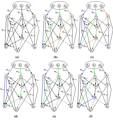
Figure 3-6: (a) All available paths between source and receiver – t1; (b, c) Two
different sets of 3 – linear disjoint paths; (d, e, f) Three different sets
of 2 – linear disjoint paths ... 35
Figure 3-7: All available paths from source –S1 to receivers {t1, t2, t3} ... 36
Figure 3-8: Available paths between sources {S1……Sh} to receivers {t1……tN} .. 36
Figure 3-9: The linear disjoint path algorithm hierarchically examines each path in
Figure 3-8 ... 38
Figure 3-10: Sets of liner disjoint paths from sources {S1……Sh} to each receiver . 39
Figure 3-11: The possible linear disjoint paths for each receiver and path overlap
over edge EG; (d) The linear network coding solution sends over
edges EG, Gt1, Gt2, Gt3, Ft2 and Ft3 . ... 43
Figure 3-12 : The system of linear equations for the receivertj. ... 44
Figure 3-13: The coding matrixes for receivers - t1,t2 and t3. ... 44
Figure 3-14: (a) A network with two sources and two receivers; (b) An information
flow decomposition diagram for the network in Fig 3-14 (a) ... 51
Figure 4-1: (a) Configuration of higher network and coding cost; (b) Configuration
Figure 4-2: (a) and (b) Adjacent matrix representation for the minimal configuration
of Figure 4-1(a) and (b) in order ... 59
Figure 4-3: (a) Network codes construction using the sparse matrix; (b) Decoding matrixes for sinks{t1,t2,t3}; (c) Decoding matrixes with finite field F2...62
Figure 4-4: Generic GA procedure ... 68
Figure 4-5: Relation between individual space, decision space, and objective space. ... 69
Figure 4-6: VEGA procedure ... 71
Figure 4-7: Solution phase for identifying the feasible minimal configurations ... 75
Figure 4-8: All available sets of 3 - linear disjoint paths for receivers {t1, t2, t3} ... 76
Figure 4-9: The search space creation process ... 78
Figure 4-10: Distance matrix for the minimal configuration in Figure 4-1(a) ... 80
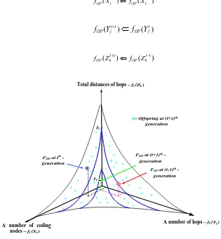
Figure 4-11: (t+1)th – generation evaluation and obtain Pareto optimal (FOP) for (t+1)th – generation ... 81
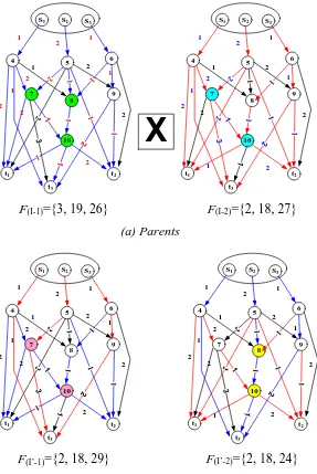
Figure 4-12: Crossover operation at gene level ... 83
Figure 4-13: Crossover operation at graph level ... 84
Figure 4-14: Mutation operation at gene level ... 85
Figure 4-15: Mutation operation at graph level ... 86
Figure 4-17: Simulation test bed ... 89
Figure 4-18: A randomly generated topology for run – 1 of project – 1 ... 91
Figure 4-19: Initial population evaluation for run -1 of project - 1 ... 92
Figure 4-20: Third generation evaluation for run -1 of project - 1 ... 93
Figure 4-22: Simulation results analysis for project – 1 ... 95
Figure 4-23: Simulation results analysis for project – 2 ... 96
Figure 4-24: Simulation results analysis for project – 3 ... 97
Figure 4-25: Simulation results analysis for project – 4 ... 98
Figure 4-26: Preliminary process analysis for all projects ... 101
Figure 5-1: Congestion, packets delay and packet misrouting exhaust network coding resources and cause decoding errors ... 107
Figure 5-2: Multiple Steiner subgraphs... 109
Figure 5-3: Sample networks ... 111
Figure 5-4: The minimal configurations with network coding resources usage; all sinks in each configuration can be simultaneously obtained the full rank matrixes ... 117
Figure 5-6: Pareto optimisation process for the problem considered (a) objective
constraints; (b) Pareto optimal front...125
Figure 5-7: (a) An individual in a path format; (b) A related sparse matrix ... 126
Figure 6-1: (a) uncoded packets are unprotected by the wire tappers; (b) coded
packets offer a natural protection against wiretapping. ... 135
Figure 6-2: A wiretap network representing the (2, 3) – threshold secret sharing
scheme. ... 136
Figure 6-3: Admissible codes for a wiretap network. ... 137
Figure 6-4: The communication system on adversaries to illustrate the problem and
proposed method. ... 146
Figure 6-5: (a) Highly vulnerable minimal subgraph G’H; (b) partially vulnerable
minimal subgraph G’L. ... 148
Figure 6-6: The packets forwarding technique at the source ... 151
Figure 6-7: Simulation results analysis, how G’L is fully protected by the
LIST OF TABLES
Table 4-1: Simulation results for project - 1 ... 95
Table 4-2: Simulation results for project – 2 ... 96
Table 4-3: Simulation results for project – 3 ... 97
Table 4-4: Simulation results for project – 4 ... 98
Table 5-1: Initial Simulation Results ... 127
Table 5-2: Simulation Results ... 128
Table 6-1: Simulation results for project – 1, each run uses a randomly generated acyclic network with a level of adversaries. ... 153
ACKNOWLEDGEMENTS
DECLARATION
This is to certify that I am responsible for the work submitted in this thesis, that the original work is my own except as specified in acknowledgments or in footnotes, and that neither the thesis nor the original work contained therein has been submitted to this or any other institution for a higher degree.
As part of the work carried out, the following paper was submitted (under review):
L.P. Karunarathne, M.S. Leeson and E.L. Hines, “Evolutionary Minimisation of Network Coding Resources”, submitted to Computer Communications,
February 2013.
ABSTRACT
Network coding (NC) is a relatively recent novel technique that generalises network operation beyond traditional store-and-forward routing, allowing intermediate nodes to combine independent data streams linearly. The rapid integration of bandwidth-hungry applications such as video conferencing and HDTV means that NC is a decisive future network technology.
NC is gaining popularity since it offers significant benefits, such as throughput gain, robustness, adaptability and resilience. However, it does this at a potential complexity cost in terms of both operational complexity and set-up complexity. This is particularly true of network code construction.
Most NC problems related to these complexities are classified as non
deterministic polynomial hard (NP-hard) and an evolutionary approach is essential to
solve them in polynomial time. This research concentrates on the multicast scenario, particularly: (a) network code construction with optimum network and coding resources; (b) optimising network coding resources; (c) optimising network security with a cost criterion (to combat the unintentionally introduced Byzantine modification security issue).
Simulations performed on randomly generated acyclic networks are used to quantify the performance of MOGA and VEGA.
Thesis Supervisor: Mark Leeson
ACRONYMS / ABBREVIATIONS USED
NC: Network coding
HDTV: High-definition television
q
: Finite field with qelement
GAs: Genetic algorithms
NP: Nondeterministic polynomial time
G(V,E): A directed graph with node set V and edge set E
'
G ∈G: G V E'( ', ')is a subgraph of Gif V'⊆Vand E'⊆E ( ,v vi j): Link or edge, v vi, j∈V; ( ,v vi j)∈E
0, 1,.... ,i j... k
v v v v v : A path from v0to vk
,
V E :A number of nodes, and a number of edges in the network G(V,E)
1
INTRODUCTION
Network coding (NC) is an elegant technique introduced to improve the efficiency
of transmission in bandwidth-hungry applications such as telecommuting, video
conferencing, e-learning, HDTV and a host of other business applications in a
multicast scenario. With the rapid integration of these applications, NC is expected to
be a critical technology for future network solutions. Moreover the network coding
technology is populating very diverse dimensions of communication networks,
because it offers significant benefits. These include throughput gain, wireless
resources savings, security enhancements, complexity suppression, robustness and
adaptability, and resilience to link failures. NC deployment is challenged by a
number of factors relating, inter alia, to code construction, resource usage and
security. This thesis concerns network coding resources, network code construction
and secure network coding with a cost criterion in a multicast scenario. This versatile
concept appeared in the network environment at the turn of the millennium, and
researchers in a diversity of fields such as computer science, mathematics and
engineering were attracted with a significant interest. Research to date has often
concentrated its efforts on overcoming these challenges which are mostly categorised
as NP-hard problems. Instead of tackling their complexity, efforts have focused on
the discovery of good solutions via evolutionary algorithms. This work provides
solutions to the same kind of problems using an evolutionary algorithm based on
genetic algorithms (GAs). The formulated problems comprise multiple objectives,
therefore a traditional generic single-objective GAs are modified to find a set of
1.1
EVOLUTIONARY APPROACHES TO NETWORK CODES
CONSTRUCTION
Network code construction is one of the major challenges in the multicast
scenario. Fragouli and Soljanin discuss two common initial procedures to construct
network codes for multicasting [1]. Given a multicast instance{G=( , ), , }V E S R , the
first common steps are:
1. Find h edge-disjoint paths {( ,S Ri j),1≤ ≤i h;1≤ ≤j N}from the source to the receivers, the associated graph ' 1 ( , )
1 i j
i h
G S R
j N
≤ ≤ =
≤ ≤
with the set ofcoding points C, and
2. Find the associated minimal configuration.
The identification of the minimal configuration with a minimum number of
coding points is NP-hard [1]. The code construction method of the proposed solution
in section 4.2 of this thesis intends to identify the minimal configuration with optimal
network and coding resources which is also defined as the NP-hard problem. The
proposed solution, based on a GA, accepts the challenge of solving this and quickly
identifies a solution instead of tackling the NP-hard problem.
1.2
EVOLUTIONARY APPROACHES TO NETWORK CODING
RESOURCE MINIMISATION
Network coding resources, their exhaustion in the multicast scenario and
evolutionary approaches to minimise them are briefly discussed here. Fundamentally,
the coding nodes are enriched in terms of buffer memory, computational capability
resources [1], [2]. These resources are rapidly consumed and ultimately exhausted by
computational complexity, packet delay, congestion, packet misrouting and so forth.
The packet delay, congestion and packet misrouting contribute to cause
synchronising errors at the coding nodes and decoding errors at the sinks. The
network coding resources for multicasting are comprehensively discussed by
Fragouli and Soljanin [1], who describe the major complexity components are as
Set-up complexity and Operational complexity.
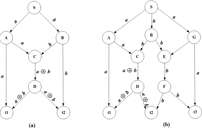
Before NC was introduced to the communication network scenario, network
nodes only performed the packet routing and duplication functions. In Figure 1-1(a)
sample network, nodes A, B, and D only perform the packet routing and duplication
functions, and packet ' 'a , ' 'b and 'a⊕b' are duplicated and routed by nodes A, B,
and D consecutively. Node C is distinguishable from the others because it is
functionally integrated by the NC technique. In Figure 1-1(a), packet ' 'a and ' 'b are
typically asynchronously reaching node C, and packet ' 'a is advanced by time T
compared to' 'b . During this time period, the input buffer memory allocates storage
for packet ' 'a and operating power is consumed to maintain the buffer. Furthermore
node C allocates its computational power to a simple exclusive-OR (XOR) binary
operation to form packet'a⊕b'.
Set-up complexity and Operational complexity and their related factors (e.g. a
number of coding nodes, a number of input links per coding nodes, etc) are
concerned in this research, and the proposed GA-based solution is discussed in
section 5.3. The former denotes the complexity of designing the network coding
scheme, which includes selecting the paths through the information flows and
perform. In Figure 1-1(b), where source S wishes to transmit data at rate 2 to the
3-leaf nodes A, B and G, and the paths should be selected through information flows
and the nodes operations of selecting paths thus be determined. Either node C or
node E should perform the coding operation to achieve the multicast rate 2. If both
nodes C and E perform the coding operation, they are unnecessary to achieve the
multicast rate 2 and cause decoding error at sink t2, consequently the operations
contribute to exhaustion of the coding resources. The latter encompasses the running
cost of using network coding, that is the amount of computational and network
resources required per information unit successfully delivered.
S
D
A B
C
t1 t2
a
b a
b
b a
S
D
A G
C
t1 t3
a
a b
b
b b b a
a
F E
t2 B
a + b
a +
b a + b
b
a +
b a
+ b a + b a
[image:23.595.160.497.343.562.2](a) (b)
Figure 1-1: Sample networks
The proposed solution in section 5.3 identifies the minimal configuration with
optimised network coding resources which is NP-hard. This minimal configuration is
1.3
EVOLUTIONARY APPROACH FOR SECURE NETWORK
CODING WITH A COST CRITERION
This is a first attempt to investigate jointly network cost, coding cost, wiretapper
adversaries and Byzantine modification in the multicast scenario. The cost
calculation is considered as a basic function of resource (network resource and
coding resource) allocation for a unit packet successfully delivered from the source
to a set of sinks during a unit time period. NC is an elegant technique to protect (i.e.
without additional security mechanisms) multicast data naturally against wire
tappers. However, it not only offers benefits but also it unintentionally allows a fatal
error which is Byzantine modification. A malicious node usually pretends to forward
packets from source to sink. Since network coding makes the coded packets at the
routers, a single corrupted packet can cause a fatal disruption to the decoding
operations at the sinks. Moreover, uncoded packets are not protected except by costly
randomness. Protecting the source messages from wiretappers via randomness is
effective but contributes to exhaustion of the resources and consequently they affect
a cost criterion. However the transmission in the network has to be randomised
because otherwise a channel output would be either a function depending on the
messages, or simply a constant.
The proposed solution in chapter 6 identifies low cost (network cost and coding
cost) minimal configurations( 'G ∈G) in an adversary network, which is categorised
as NP-hard; an evolutionary approach is essential to solve it. TheseG's are classified
as highly vulnerable '
H
G s and lower vulnerable '
L
G s. The '
L
G s can only be protected
wiretapper adversaries cannot be detected. Simulation results show that
multi-objective GA based techniques in the proposed solution have a high potential to
identify the '
L
G s. Nevertheless, these may still not be perfectly protected because they
may be comprised of malicious nodes. The network G is assumed to be error free and
'
L
G s are examined for malicious nodes. Moreover links which deliver uncoded
packets in '
L
G s are still threatened by the wiretappers, and they are perfectly
protected by the proposed random coding and packet forwarding technique at the
source without costly randomness.
1.4
CONTRIBUTIONS
Most problems in the NC concept are NP-hard and traditional solving methods
(optimising, searching) have not been able to provide feasible solutions or tackling
the problems. In this circumstance, this research introduces a new pathway to find a
feasible solution instead of tackling the NP-hard problems. The aspiration is an
identification of minimal configurations; sets of linear disjoint paths are combined by
an evolutionary algorithm based on the GA. The approach introduces how diverse
sets of parameters (e.g. network resources, coding resources etc.) are simultaneously
optimised and include them into the minimal configurations identified.
Network code construction is a challenge and it is fatally affected by setup
complexity (complexity of identifying paths through coding points and satisfying
multicast demands such as the min-cut max-flow theorem). The proposed solution in
chapter 4 is an excellent contribution to smooth out the complexity and provides
NC resource is excessively consumed by computational complexity and the
complexity is affected by a selected network coding scheme, a number of coding
nodes which perform during the multicast transmission and a number of in-links for
each coding node. Chapter 5 discusses the contribution via optimisation of the NC
resource; the proposed method identifies the minimal configuration with optimal
coding resources which is defined as NP-hard. The significant point is that the source
is able to obtain explicit information about the coding operations and can select a
limited size of finite field to its multicast transmission.
Network security is a vital topic in the cyber world. Most security mechanisms
against adversaries entirely concerned with strengthening their security level instead
of cost. Chapter 6 contributes to its proposed solution to develop a low cost secure
network coding scheme against wiretapper adversaries and Byzantine modifications
1.5
REFERENCES
[1] C. Fragouli and E. Soljanin, “Network Coding Fundamentals”, Foundation
and Trends in Networking,Vol 2, no.1, pp.1-133,2007.
2
BACKGROUND TO THE RESEARCH
This chapter is allocated to providing an infrastructure to this thesis. Section 2.1
offers an overview of network coding. Section 2.2 discusses finite field operations.
Section 2.3 shows the benefits of network coding. Section 2.4 includes the
disadvantages of network coding. Section 2.5 is allocated to briefly discuss network
coding applications. Section 2.6 consists of prior work in network coding relevant to
this thesis.
2.1
OVERVIEW OF NETWORK CODING
All communication networks today make a basic assumption that information is
separate. Thus, whether it is packets in the Internet, or signals in a phone network, if
they originated from different sources, they are transmitted much in the same manner
as cars on a transportation network of highways, or fluid through a network of pipes.
That is, independent data streams may share network resources but the information
itself is separate. Most network functions such as routing, data storage and error
control are based on this assumption.
This assumption is broken by network coding as it allows intermediate nodes in
the network to combine their input packets into one or more output packets. Network
coding is best demonstrated through the famous butterfly network which is given in
the seminal paper [1] of Ahlswede et al, shown in Figure 2-1. Each source produces
one bit per unit time slot (unit rate sources).
If sink t1 uses all the network resources by itself, it is able to receive both packets
1 ,
a
S t and the packet ' 'b by source Sb along S C D tb, , , 1 , as depicted in
Figure 2-1(a). Similarly, if sink t2 consumes all network resources by itself, it could
also receive both ' 'a and' 'b , as depicted in Figure 2-1(b).
Now assume that both sinks want to receive the information from sources Sa and
Sb simultaneously. If routers C and D only forward the packets they receive, the
middle link ( ,C D)will be a bottleneck arising from the fact that only one packet
(1bit) per unit time slot through may be sent via this edge. However, packets ' 'a and
' 'b are simultaneously sent to reach the sinks t2 and t1 consecutively.
D Sa
C
t1 t2
a ⊕ b
a 1bit Sb 1bit a 1bit
a ⊕ b
1bit
a ⊕ b
1bit b 1bit b
1bit
a ⊕ a ⊕ b = b b ⊕ a ⊕ b = a
D Sa
C
t1 t2
a 1bit Sb a 1bit b 1bit b 1bit a b D Sa C
t1 t2
a 1bit Sb a 1bit b 1bit b 1bit a b
(a) Routing to t1 (b) Routing to t2 (c) Network coding
Figure 2-1: The Butterfly network. Sources Sa and Sb multicast their information to
sinks t1 and t2.
Conventionally, information flow was considered similar to fluid through pipes,
and independent information flows were distinct. Considering this approach node C
would have to make a decision regarding forwarding the input packets: either use
link ( ,C D)to send packet' 'a , or use it to send packet' 'b . Thus, when packet ' 'a is
chosen, sink t1 will only receive ' 'a and sink t2 will receive both ' 'a and' 'b , and vice
The simple but vital observation was made in the seminal work by Ahlswede et.
al.[1] that intermediate nodes in the network are allowed not only to forward their
incoming information streams but also process them prior to forwarding. In
particular, node C is able to combine packets ' 'a and' 'b using an XOR (binary
addition over binary field) binary operation and create a third packet 'a⊕b' (1bit) it
can then send through link ( ,C D), as depicted in Figure 2-1(c). The sinks t1 and t2
receive packets
{
' ', 'a a⊕b'}
and{
' ', 'b a⊕b'}
consecutively, and can easily solve toretrieve the packets ' 'a and' 'b .
The XOR operation in network coding may be replaced by linear network coding
to allow for a much larger degree of flexibility in the way that packets can be
combined. Thus, routers combine packets linearly instead of simply forwarding them
to create coded packets. The encoding and decoding processes are briefly described
in the following sections.
2.1.1
E
NCODINGAssume that each packet consists of L bits. When the packets to be combined, if
their sizes are not equal, the shorter ones are padded with trailing 0s. Each packet is
represented as k consecutive bits of a symbol over the finite field 𝔽2k; thus each
packet is a vector of L/k symbols. The linear network coding allows intermediate
nodes in the network to combine their incoming packets linearly over the finite field 𝔽2k. The linear combination uses addition and multiplication over the finite field 𝔽2k.
For example when k = 1, then the finite field 𝔽21 = {0, 1} has a one bit symbol and a
field size of 2; when k = 2, the size 4 finite field as 𝔽22 = {00, 01, 10, 11} is obtained,
The discussion is initiated with the standard framework. An acyclic graph G(V,E)
consists of unit capacity edges, a sender S∈V, and a set of receivers t t1, 2… ∈tN T.
The multicast capacity h is the minimum number of edges in any cut between the
sender and a receiver, which implies that h- unit rate sources are present. Each edge
e∈Eemanating from a node v=In e
( )
(v V∈ )carries a symbol y e( )
that is a linearcombination of the symbol y e( )’ on the edges e’ entering v, namely,
': ( ') e( ') ( ')
e out e =v m e y e
∑
. The local encoding vector( )
( )
e’: ( ’)
’
e out e v
e = m e =
m represents
the encoding function at node v along edge e. If v is the sender S, then to maintain
uniformity of notation, virtual edges e1'...eh' entering S, carrying the h source
symbols '
( )i i, 1,...
y e =x i= h are introduced. Thus by induction y e( )on any edge
e∈Eis a linear combination
1
( ) h i( ) i
i
y e =
∑
= g e x of the source symbols, where the hdimensional vector of coefficients g e( )=[ ( ),...g e1 g eh( )]
can be determined
recursively by
': ( ')
( ) e( ') ( ')
e out e v
g e =
∑
= m e g e
, where ,
( )i
g e on the artificial edge ,
i e is
initialised to the th
i unit vector. The vector g e( ) is known as the global encoding
vector along edge e. Any receiver t t1, ....2 tN∈Tcan receive the symbols
[
( ) ( )... ( )1 2]
T h
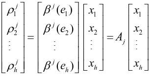
y e y e y e along its h (or more) incoming edgese1...eh. Each receiver can obtain the source symbol x x1, ...2 xh by solving the equations in Figure 2-2 and
the matrix Gt of global encoding vectors g e( )=[g e1( ),...1 g eh( )]h
should be of full
1 1 1
1 1 1 1 1
1 ( ) ( ) ( ) ( ) ( ) ( ) ( ) ( ) h t
h h h h h h h h
g e g e
y e x g e x x
G
y e g e g e x g e x x
= = =
Figure 2-2: The system equation for linear network coding model.
The full rank stipulation of the matrix Gt can be satisfied with high probability if
local encoding vectors m
( )
e are generated randomly, which is called Random LinearNetwork Coding and the symbols of m
( )
e lie in the finite field (𝔽q) of sufficient size(q- sufficiently large). Jaggi et al.[2] showed that with the finite field (𝔽216) having
field size (q = 216) and a number of edges in the network that is at most |E| = 28, then the matrix Gt at any given receiver will have full rank with a probability of at least
1 – 2- 8 = 0.996.
In a packet network, the symbols y(e) carried along an edge e can be grouped into packets. Thus the symbols y(e) flowing on each edge e are packetized into vectors
1 2
( ) ( ), ( ),... ( )
Y e =y e y e y eψ of the appropriate length (depending on the field size), and now each of these vectors can be expressed as a linear combination
': ( ')
( ) e out e v e( ') ( ')
Y e =
∑
= m e Y e of the vectors Y(e’) on the edges e’ entering v = In(e).Likewise, the source symbols xiare packetized flowing into the sender on the artificial edges ei' into vectorsXi=[xi,1,xi,2....,xi,ψ]so that any receiver can recover (with high probability) the h source vectors X X1, 2...,Xhfrom any h received packets,
1 1 2 1 1 1,1 1,2 1,
1 1
1 2 ,1 ,2 ,
( ) ( ) ( )
( )
( ) ( ) ( ) ( )
t t
h h h h h h h h
y e y e y e x x x
Y e X
G G
Y e y e y e y e X x x x
ψ ψ ψ ψ = = =
2.1.2
D
ECODINGAssume any sink or receiver has received the set[ ( ), ( )],...[ (g e Y e1 1 g em), (Y em)].
To retrieve the original packets, it is necessary to solve the system equations in
Figure 2-2. This is a linear system with m equations and h unknowns and the
condition m≥hmust be satisfied to have a chance of recovering all data, i.e. the
number of received packets needs to be at least as large as the number of original
packets. Conversely, the condition m≥h may not be satisfied as some of the
combinations might be linearly dependent (Appendix A1).
In practice, decoding requires solving a set of linear equations, which can be
accomplished efficiently using Gaussian elimination. Each sink or receiver node
stores the encoded vectors g e( ) it receives as well as corresponding packetsY e( ),
row by row, in a so-called decoding matrix. Initially, the matrix is empty. When an
encoded packet is received, it is inserted as the next row in the decoding matrix and
Gaussian elimination is performed to transform it to an upper triangular matrix
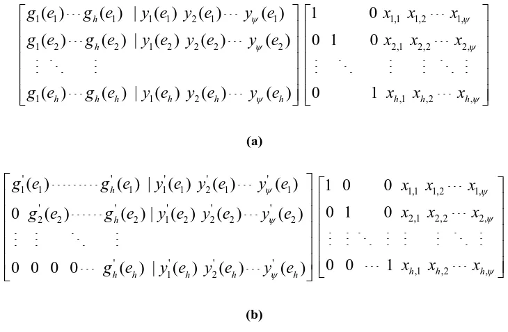
(Appendix A2). Figure 2-4 shows how Gaussian elimination progresses for the
Figure 2-3 system equations.
A received packet is called innovative if it increases the rank of the matrix, i.e. the
packet is linearly independent. If a packet is non-innovative, it is reduced to a row of
0s by Gaussian elimination and is ignored, i.e. the packet is linearly dependent.
Instantly, the matrix consists of a row of the form{g e'j( ) |j y e1'( )j y e2'( )j y eψ' ( )}j ,
where j is any row of the upper triangular matrix in Figure 2-4(b). The form is same
as the bottom row of Figure 2-4(b) and the sink or receiver can obtain the original
' ' ' ' ' '
,1 1 ,2 2 ,
{xh ≡g eh( )h y e( );h xh ≡ g e y eh( )h ( )h xhψ ≡g e y eh( )h ψ( )}h . Note that decoding
does not need to be performed at all nodes of the network, but only at the receivers.
1 1 1 1 1 2 1 1 1,1 1,2 1,
1 2 2 1 2 2 2 2 2,1 2,2 2,
1 1 2 ,1 ,2 ,
( ) ( ) | ( ) ( ) ( ) 1 0
( ) ( ) | ( ) ( ) ( ) 0 1 0
( ) ( ) | ( ) ( ) ( ) 0 1
h
h
h h h h h h h h h
g e g e y e y e y e x x x
g e g e y e y e y e x x x
g e g e y e y e y e x x x
ψ ψ ψ ψ ψ ψ (a) ' ' ' ' '
1 1 1 1 1 2 1 1 1,1 1,2 1,
' ' ' ' '
2,1 2,2 2,
2 2 2 1 2 2 2 2
' ' ' '
,1 ,2 ,
1 2
( ) ( ) | ( ) ( ) ( ) 1 0 0
0 1 0
0 ( ) ( ) | ( ) ( ) ( )
0 0 1
0 0 0 0 ( ) | ( ) ( ) ( )
h
h
h h h
h h h h h
g e g e y e y e y e x x x
x x x
g e g e y e y e y e
x x x
g e y e y e y e
[image:34.595.143.508.156.395.2]ψ ψ ψ ψ ψ ψ (b)
Figure 2-4: (a) the system equations compose to the “augmented matrix equation”; (b) perform
elementary row operations to put the augmented matrix into the upper triangular form
2.1.3
P
RACTICAL ISSUESPractical issues in encoding and decoding are basically related to the size of the
decoding matrix and the size of the finite field. For practical purposes, both
parameters have to be limited. This can be achieved by grouping packets into
generations, and mandating that only packets in the same generation can be
combined linearly [3]. Moreover the parameters are limited by deterministic network
codes but it is more difficult with random network coding. The size of the generation
significantly affects the performance of network coding and it is related to the size of
the finite field. Typically, a small finite field increases the probability of
2.2
FINITE FIELD OPERATIONS
Network coding requires operations in the binary field (q,q= 2k), i.e. operations on
strings of k-bits, which is popular as the Galois field1 GF(q), where q is a number of elements in the field. One way to construct 2k is to use a polynomial basis
representation. Here, the elements of 2kare the binary polynomials (polynomial
whose coefficients are in the field 1
{ }
2 = 0, 1 of degree at most k – 1:
{
1 2 2 1 0}
1 2 2 1 0
2k ... : {0,1}
k k
k k i
a − z − a − z − a z a z a z a
= + + + + + ∈
An irreducible binary polynomial f z( ) of degree k is chosen; the irreducibility of
( )
f z means that it cannot be factorised as a product of binary polynomials each of
degree less than k. The addition of field elements is the usual addition of
polynomials, with coefficient arithmetic performed modulo 2 (Appendix A3.1). The
multiplication of field elements is performed modulo the reduction polynomial f z( ),
(Appendix A3). For any binary polynomiala z( ),a z( ) mod f z( ) shall denote the
unique remainder polynomialr z( ) of degree less than k obtained upon long division
of a z( ) by f z( ); this operation is called reduction modulo ( )f z , (Appendix A3).
1 French mathematician Évariste Galois
2.3
THE BENEFITS OF NETWORK CODING
Network coding provides benefits in a wide variety of scenarios, such as static
wired or wireless networks, ad-hoc mobile wireless networks, wireless sensor
network and optical networks[10],[4]. These benefits facilitate improvements in
network throughput and security, saving resources. Network coding offers robustness
and adaptability to a traditional multicast routing network. Moreover the complexity
of content distribution is minimised by network coding.
2.3.1
T
HROUGHPUT GAIN IN A STATIC ENVIRONMENTIn communication networks, such as Ethernet or packet radio, throughput is
described as the average rate of successful message delivery over a communication
channel. These channels are basically physical or logical links. The throughput is
usually measured by the unit of bits or bytes per second (bits/sec or bps) or by the
data packet per second. Maximum throughput in each channel is constrained by its
channel capacity and network coding is a promising method to improve this.
The primary result [1] shows that network coding can increase the capacity of a
network for multicast flows. Consider a network in Figure 2-1 (a) or (b), sinks t1 and
t2are interested in simultaneously receiving data from both sources Sa and Sb. Each
sink needs all the network resources when only traditional network routing is
employed but as illustrated in Figure 2-1 (c), network coding allows to both sinks to
receive data from both sources.
Network coding may offer throughput benefits not only for multicast flow, but
now assumed that source Sa needs to transmit to the sink t2 and source Sb needs to
transmits to sink t1. With network coding the source can send at rate 1 (1bit/sec) to
each receiver as opposed to only ½ (0.5 bit/sec) without.
In the multicast scenario, with network coding, the source can send at rate 2
(2bit/sec) to each receiver. But the source can maximally achieve the rate 1½ (1.5
bit/sec) to each receiver if a network uses a traditional multicast routing. The reason
for this difference is, network coding allows the combining of two bits into one time
slot (1 sec) at node C in Figure 2-1 (c).
2.3.2
S
ECURITYSending linear combinations of packets instead of uncoded data offers a natural
way to take advantage of multipath diversity for security against wiretapping attacks.
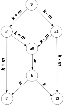
The wiretap network (shown in Figure 2-5 with admissible codes) consists of a
communication network and a collection of subsets of wiretap channels. Any link is
susceptible to wiretapper adversaries and the admissible codes protect a source
message m from wiretappers. The source generates a random packet k and combines
it with the message m. The packets k+m and k-m are encoded at node ‘a0’, and the
packet k encoded is forwarded to sink t1 and t3.The admissible codes allow legal
users t1, and t3 to obtain m without any errors. Moreover the wiretapper cannot
obtain information about the secure message by accessing any 1- channel. Thus
networks that only require protection against such simple attacks can obtain this
S
b
a1 a2
a0
t1 t3
k
k + m
k - m
k + m
k - m
k
- m
k
+
m
[image:38.595.272.381.88.272.2]k k
Figure 2-5: Single-edge wiretap butterfly network with secure network code.
2.3.3
W
IRELESS RESOURCESIn a wireless environment, network coding can be used to offer benefits in terms
of battery life of intermediate nodes or base stations, wireless bandwidth and delay.
Consider the wireless ad-hoc network shown in Figure 2-6, where devices A and C
need to exchange the binary files x1 and x2 via B as a relay. Presumably time is
slotted and each device transmits and receives a file during a timeslot (half-duplex
communication). As Figure 2-6(a) depicts, nodes A and C send their files to the relay
B, and this forwards each file to the corresponding destination.
The network coding approach improves the natural capability of wireless channels
for broadcasting and their resource utilization. As Figure 2-6(b) shows, node C
receives both files x1 and x2, and performs on them a XOR binary operation to create
the filex1⊕x2, which it then transmits to both receiver A and C using a common
transmission. Node A has x1 and can thus decode x2. Node C performs as Node A.
Consequently, the network coding approach offers benefits in terms of energy
three instead of four timeslots), and wireless bandwidth (the wireless channels are
occupied for a smaller amount of time and the file x1⊕x2 is not consumed an
excessive bandwidth to fulfil their transmissions).
A B C
A B C
A B C
A B C
A B C
A B C
A B C
x1
x1 x1
x2
x2 x2
x2
x1⊕ x2
x1
x1⊕ x2
(a) Without network coding (b) With network coding
Figure 2-6: Node A and C exchange information via relay B. The network coding approach
saves one broadcast transmission.
2.3.4
R
OBUSTNESS AND ADAPTABILITYThis is a vital topic to discuss under network coding benefits. Network coding can
offer significant benefits in terms of operational complexity in dynamically changing
environments, such as wireless networks, which frequently change because nodes
move, turn on and off or roam out of range. In such environments, networks are
restricted to use very simple distributed algorithms to avoid cost of storing because
details of topology (availability of nodes and links) are changed rapidly.
Now Figure 2-6 is considered again with the assumption that node A and C may
go into sleep mode (or may move out of range) at random without notifying the node
B (wireless base station). If the base station B broadcasts x1 or x2, the transmission
receive it. However, if the base station broadcasts x1⊕x2 instead of x1 or x2, (or
more generally, random linear combinations of the information packets) the
transmission will bring new information to all active nodes. Either A or C will be
woken up, so as to obtain x1 or x2 by decoding and send an acknowledgment to the
base station. Then the base station can terminate their transmission to either A or C.
2.4
POTENTIAL DISADVANTAGES OF NETWORK CODING
This section is allocated to discuss the disadvantage of network coding. Network
coding offers not only the benefits but also it comes with some potential
disadvantages which it is vital to discuss in here.
2.4.1
C
OMPLEXITYThe two complexities, set-up complexity and operational complexity, accompany
network coding [1]. The former is the complexity of designing the network coding
scheme, which consists of selecting the paths through information flows, and
determining the operations (coding, forwarding) that the nodes of the network
perform. In a time-variant network2, such as wireless ad-hoc networks, this complexity is higher because a routing table in each node should be updated in the
time domain.
Operational complexity is defined as the amount of computational and network
resources required per information unit successfully delivered. Again this complexity
is strongly correlated with the network coding scheme employed. In linear network
2 The nodes and links in the network are moved with reference to time
coding, a linear combination of h information streams at each coding node requires
2 (h )
Ο operations over finite field 𝔽q; to recover the source symbols, each receiver
needs to solve a system of h h× linear equations, which requires Ο( )h3 operations
over 𝔽q, if Gaussian elimination is used. Moreover the network nodes should be
upgraded with additional functionalities (XOR, Gaussian elimination).
2.4.2
D
ELAYLink delay is a general term used for any transmission network, but it causes fatal
effects in network coding, and Section 1.2 discussed how it affects network coding.
In practical network coding, a delay-free assumption is denied and therefore
coding and decoding delays are essentially considered. These delays are depended on
a number of factors, which are: the network coding scheme, the finite field size, the
number of coding nodes occupied to fulfil the multicast transmission, the average
number of in-links per coding node, and the size of the decoding matrix (see section
2.1.3). Consequently, overall delays contribute to exhausting network and coding
resources, and degrade network coding performances.
2.4.3
S
ECURITYUnexpectedly network coding allows access to a fundamental network threat
which is called a Byzantine modification, which can cause catastrophic fatal damage
to network multicasting. This mixing of information can be catastrophic if the
network consists of Byzantine nodes, i.e., malicious internal nodes that pretend to be
routers but instead eavesdrop on transmissions and inject fake packets, with the
corrupted information may be mixed with all the information flowing in the network,
causing decoding errors.
2.5
NETWORK CODING APPLICATIONS
Network coding applications, their benefits and performance, are discussed
thoroughly in [4] and [5]. Large content distribution systems, such as Bit Torrent and
Microsoft Security Content Distribution (MSCD), are examples of peer-to-peer
(P2P) systems. Minimum download times and more robustness are benefits that
network coding offers to P2P systems. For bidirectional traffic in a wireless network
(Figure 2-6(b)), network coding improves throughput when two wireless nodes
communicate via a common base station. Other applications are residential wireless
mesh networks, many-to-many broadcast, ad-hoc sensor networks, network
tomography, and network security.
2.6
KEY PREVIOUS WORK ON NETWORK CODING
This section is allocated to discuss prior works in network coding relevant to this
thesis. In their seminal research, Ahlswede et al. [1] illustrated that if network coding
is permitted over the nodes of a network, the communication rate can be improved
over that obtainable by routing alone. Li et al. [6] showed that linear coding is
sufficient for multicast network coding problems, i.e., codes in which each packet
sent over the network is a linear combination of the original packets. Koetter and
Médard [7] introduced an algebraic framework for the study of network coding and
gave a condition for valid codes. This framework was used by Ho et al. [8] to show
algorithm. Jaggi et al. [9] proposed a deterministic polynomial-time algorithm for
2.7
REFERENCES
[1] R. Ahlswede, N. Cai, S.-Y. R. Li, and R. W. Yeung, “Network information
flow”, IEEE Trans. Information Theory, vol. IT-46, no.4, pp.1204-1216, July
2000.
[2] S. Jaggi, P. Sanders, P. A. Chou, M. Effros, S. Egner, K. Jain, and L.Tolhuizen, “Polynomial time algorithms for multicast network code construction,” IEEE Trans. Information Theory, vol. 51, no. 6, pp. 1973-1982, 2005.
[3] P. A. Chou, Y. Wu, and K. Jain. Practical network coding. In Allerton, Oct. 2003.
[4] C. Fragouli and E. Soljanin, “Network Coding Applications”, Foundation
and Trends in Networking,Vol 2, no.2, pp.135-269,2007.
[5] C. Fragouli, J. Y. Le Boudec and J. Widmer, Network Coding: An Instant Primer, ACM SIGCOMM Computer Communication Review, Volume 36, Number 1, January 2006, pp. 63-68
[6] S.-Y. R. Li, N. Cai and R. W. Yeung, “Linear Network Coding”, IEEE Trans.
Information Theory, vol. 49, no.4, pp.371-381, 2003.
[7] R. Koetter and M. Médard, “An algebraic approach to network coding”,
IEEE/ACM Trans. Networking, vol. 11, no. 5, pp. 782–795, 2003.
[8] T. Ho, R. Koetter, M. Médard, D. Karger, and M. Effros, “The benefits of coding over routing in a randomized setting”, in Proc. IEEE Int. Symp.
Information Theory, Yokohama, Japan, Jun./Jul. 2003, p. 442.
3
ALGORITHMIC SOLUTIONS FOR NETWORK
CODING PROBLEMS
Network coding problems are theoretically or practically solved by algorithmic
solutions with computer networks being mapped into the algorithmically useful
framework of graphs. These can be defined as a data structure and into which the
problem to be solved is mapped. Graph based algorithms are developed based on
graph theories [1] based on objects termed vertices or nodes which are related via
edges or links. Computer networks are usually mapped into directed graphs, with
nodes representing equipment such as routers and switches, and links representing
wired or wireless network channels.
This chapter provides the first part of the underpinning for the solutions proposed
in this thesis by discussing network code design algorithms for multicasting and the
evolutionary approach for network code design. Section 3.1 discusses network
multicast whilst section 3.2 covers network code design algorithms for multicasting.
The subsequent chapter will introduce an evolutionary approach for network code
design.
3.1
NETWORK MULTICAST
Network multicast refers to transmitting simultaneously the same information to
multiple receivers in the network [2]. A simple example of multicasting is sending an
e-mail message to a mailing list. In this research, the concept is expanded to cover
transmitting simultaneously different sets of the same information to multiple
simultaneously client security definitions. However, the clients use different
platforms (e.g. Linux or Windows) with which the definition should be compatible.
Therefore, it is necessary to transmit simultaneously compliant and varied definition
sets in the same update version.
3.1.1
G
RAPH REPRESENTATION FOR MULTICASTINGThis section describes essential elements of the proposed solutions constituting
the preliminary processes for all subsequent network coding solutions. A graph is
considered as a directed acyclic graph (DAG) and there are no directed cycles or
negative cycles [13]. The nodes of a DAG can be topologically sorted into a
sequence v v1, 2,...,vn such that ( ,v vi j)∈E impliesi< j. A topological order of a
directed acyclic graph G V E( , ) can be computed in linear time O m( +n) where
,
m= E n=V using either depth-first search (DFS) or breadth-first search (BFS)
algorithms. The nodes on any path in a DAG increase in topological order.
3.1.1.1 Adjacency Matrix Representation
An n-node graph can be represented by an n n× adjacency matrix M in whichMij is 1 if ( , )i j ∈Eand 0 otherwise. Edge insertion or removal and edge queries work in
constant time. It takes time O n( ) to obtain the edges entering or leaving a node.
Each node in the graph has adjacent nodes whose edges can be represented as an
adjacent vector. The graph is formed as the adjacent matrix combining all adjacent
vectors. This representation can be generalized to store additional information such
as edge weights in a separate matrix, the weight matrix W, and is an efficient and
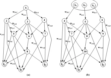
In Figure 3-1(a) shows a DAG, and its adjacent matrix representation and weight
matrix are consecutively shown in Figure 3-2 (a) and Figure 3-2 (b). Each row of the
adjacent matrix represents the adjacent vector belonging to each node in the DAG.
S
2 3 4
5
6 7
t1 t2
8
t3
wS-2 wS-4 wS-3
w2-t1
w2-t3 w2-5
w2-6
w5-t1
w4-t2
w7-t2 w3-t2
S1
4 5 6
7
8 9
t1 t2
10
t3
wS-2 wS-4 wS-3
w2-t1
w2-t3 w2-5
w2-6
w5-t1
w4-t2
w7-t2 w3-t2 S2 S3
[image:48.595.137.505.183.442.2](a) (b)
Figure 3-1: (a) Directed acyclic graph (DAG) with links weight; (b) The DAG for multicast
1 2 3
1
2
3
1 2 3
,2 ,3 ,4
2,5 2,6
2 3 4 5 6 7 8
0 1 1 1 0 0 0 0 0 0 0 2 0 0 0 0 1 1 0 0 1 0 1 3 0 0 0 0 1 1 1 0 1 1 0 4 0 0 0 0 0 1 1 0 0 1 0 5 0 0 0 0 0 0 0 1 1 0 1 6 0 0 0 0 0 0 0 1 0 0 0 7 0 0 0 0 0 0 0 0 0 1 1 8 0 0 0 0 0 0 0 0 1 1 1 0 0 0 0 0 0 0 0 0 0 0 0 0 0 0 0 0 0 0 0 0 0 0 0 0 0 0 0 0 0 0 0 0
( )
2 3 4 5 6 7 8
0 0 0 0 0 0 0 0
2 0 0 0 0
S S S
S t t t
S
t
t
t
a
S t t t
S w w w
w w 1 3 1 2 2 1 3 2 3
1 2 3
2, 2,
3,5 3,6 3,7 3, 3,
4,6 4,7 4,
5,8 5, 5,
6,8
7, 7,
8, 8, 8,
1
2
3
0 0 0
3 0 0 0 0 0 0
4 0 0 0 0 0 0 0 0
5 0 0 0 0 0 0 0 0
6 0 0 0 0 0 0 0 0 0 0
7 0 0 0 0 0 0 0 0 0
8 0 0 0 0 0 0 0 0
0 0 0 0 0 0 0 0 0 0 0
0 0 0 0 0 0 0 0 0 0 0
0 0 0 0 0 0 0 0 0 0 0
( ) t t t t t t t t t
t t t
w w
w w w w w
w w w
w w w
w
w w
w w w
t
t
t
b
Figure 3-2: (a) Adjacent matrix representation for DAG in Figure 3-1; (b) Weight matrix for
DAG in Figure 3-1(a)
3.1.1.2 Adjacent Matrix Representation for Multicast Network - M
Figure 3-1(b) shows a multicast representation of the DAG in Figure 3-1(a). The
source S is split into h-sub sources or individual data streams, and they are
represented as individual nodes. In Figure 3-1(b) shows a 3-subsource multicast
network, and its adjacent matrix and weight matrix are consecutively represented in
Figure 3-3 (a) and (b). The proposed solutions for the network coding problems are
1 2 3 1 2 3 1 2 3 1 2 3
4 5 6 7 8 9 10
0 0 0 1 0 0 0 0 0 0 0 0 0 0 0 0 0 1 0 0 0 0 0 0 0 0 0 0 0 0 0 1 0 0 0 0 0 0 0 4 0 0 0 0 0 0 1 1 0 0 1 0 1 5 0 0 0 0 0 0 1 1 1 0 1 1 0 6 0 0 0 0 0 0 0 1 1 0 0 1 0 7 0 0 0 0 0 0 0 0 0 1 1 0 1 8 0 0 0 0 0 0 0 0 0 1 0 0 0 9 0 0 0 0 0 0 0 0 0 0 0 1 1 10 0 0 0 0 0 0 0 0 0 0 1 1 1 0 0 0 0 0 0 0 0 0 0 0 0 0 0 0 0 0 0 0 0 0 0 0 0 0 0
0 0 0 0
S S S t t t
S S S t t t 1 2 3 1 3 1 2 2 1 3
1 2 3 1 2 3
1 ,4
2 ,5
3 ,6
4,7 4,8 4, 4,
5,7 5,8 5,9 5, 5,
6,8 6,9 6,
7,10 7, 7,
0 0 0 0 0 0 0 0 0 ( )
4 5 6 7 8 9 10
0 0 0 0 0 0 0 0 0 0 0 0
0 0 0 0 0 0 0 0 0 0 0 0
0 0 0 0 0 0 0 0 0 0 0 0
4 0 0 0 0 0 0 0 0 0
5 0 0 0 0 0 0 0 0
6 0 0 0 0 0 0 0 0 0 0
7 0 0 0 0 0 0 0 0 0 0
8 0 S S S t t t t t t t a
S S S t t t
S w
S w
S w
w w w w
w w w w w
w w w
w w w
2 3
1 2 3
8,10
9, 9,
10, 10, 10,
1
2
3
0 0 0 0 0 0 0 0 0 0 0
9 0 0 0 0 0 0 0 0 0 0 0
10 0 0 0 0 0 0 0 0 0 0
0 0 0 0 0 0 0 0 0 0 0 0 0
0 0 0 0 0 0 0 0 0 0 0 0 0
0 0 0 0 0 0 0 0 0 0 0 0 0
( )
t t
t t t
w
w w
w w w
t t
t
b
Figure 3-3: (a) Adjacent matrix representation for the multicast DAG in Figure 3-1(b);
(b) Weight matrix for the multicast DAG in Figure 3-1(b)
3.1.1.3 Adjacent Matrix Representation for Dynamic Multicast Networks
When nodes move randomly and their links with adjacent nodes thus appear and
disappear, a dynamic multicast network is formed, meaning that each adjacent vector
may vary in the time domain with consequent updating of the adjacent matrix