Charpy Impact of Sandwich Structural Composites (CFRP
/
PC
/
CFRP)
of Polycarbonate (PC) Cores Covered with Carbon Fiber Cross Textile
Reinforced Epoxy Polymer (CFRP) Thin Sheets
as a Function of Temperature
Yoshitake Nishi
1, Naoya Tsuchikura
1,+, Shinichiro Nanba
1,+,
Tatsuya Yamamoto
1,+and Michael C. Faudree
1,21Department of Metallurgical Engineering, Graduate School of Engineering, Tokai University, Hiratsuka 259-1292, Japan 2Center of Foreign Language, Tokai University, Hiratsuka 259-1292, Japan
The purpose of this study is to investigate a lighter, cheaper and possibly stronger alternative to CFRP, by obtaining the Charpy impact values (auc) of a sandwich structural composite (CFRP/PC/CFRP) constructed of a polycarbonate (PC) core between two thin plies of carbon cross textilefiber/epoxy (CFRP) within the temperature range of aircraft operation, from 200 to 403 K below the glass transition temperature of PC (Tg=422 K). Theaucof CFRP/PC/CFRP were compared with a 2.0 mm thick 12-ply CFRP laminate. Results showed overall, the CFRP/ PC/CFRP had higheraucthan the CFRP at each fracture probability (Pf) from 300 to 373 K except at 200 K with lowPfand 403 K with highPf. Specifically, although the volume fraction of carbonfiber (12%) of CFRP/PC/CFRP was much smaller than that (60%) of the CFRP, theaucat room temperature (300 K) of CFRP/PC/CFRP was approximately 64%higher than that of CFRP at mid-fracture probability (Pf) of 0.50. Fracture modes of CFRP/PC/CFRP were explained by delamination between PC core and the CFRP thin sheet surfaces, bending plastic deformation, and CFRP fracture. The highest Weibull coefficient (n) was obtained at 323 K. Based on the 3-parameter Weibull equation, the limiting impact value (as) also exhibited the highest value at 323 K. In addition, the cost of CFRP/PC/CFRP was 40%lower than that of CFRP at the time of this study. Since the use of PC resin as the core enhanced the safety design at low cost, practical use of sandwich structural composites of CFRP/PC/CFRP is possible. [doi:10.2320/matertrans.M2011357]
(Received December 8, 2011; Accepted April 9, 2012; Published May 30, 2012)
Keywords: sandwich structure, carbonfiber reinforced polymer (CFRP), epoxy, polycarbonate, Charpy impact test, delamination
1. Introduction
Carbonfiber reinforced polymer (CFRP) has been utilized for light structural materials with high strength.1,2) The
further strengthening with safety enhancement has been always expected to develop high-speed transport vehicles with safety and low energy consumption. However, the high strength carbon fiber, whose supply often cannot catch up with demand exhibits a high cost.
On the other hand, sandwich panels made with laminate skins and light-weight cores are commonly employed in the aerospace, marine, automotive and recreational industries. With their superior bending stiffness, low weight, good thermal insulation, acoustic damping, ease of machining and high corrosion resistance sandwich panels exhibit advantages over metallic materials. Conversely, limitations include possible low interlaminar shear strength and susceptibility to impact damage, especially between the core and face sheets. Traditionally, damage by a hemispherical impactor is initiated as a point force on the center of a square or rectangular specimen³70 to 150 mm2by slow point force,3)
drop tower, or projectile.47)For low energy tests, impact is followed by non-destructive testing (NDT) with an ultrasonic transducer to detect delamination undetectable to the eye which can reduce strength significantly. Compression after impact (CAI) testing is often conducted after point impact in aerospace materials such as quasiisotropic CFRP for safety design.8,9)
Five fracture modes in composite laminates and sandwich panels undergoing point impact have been identified: core
crushing, core cracking, delamination in the impacted face sheet, matrix cracking, and fiber breakage in the face sheets.10) This method of point impact fracture followed by
CAI for aircraft CFRP has been generally studied to evaluate safety against impact accidents such as bird strike, volcanic rock or hailstone on aircraft CFRP.11,12)
On the other hand, the Charpy impact test utilizes a drop-weight pendulum and evaluates the impact absorption characteristics and relative impact toughness of materials often used in quality control applications employed as an inexpensive and fast way to estimate reaction to higher velocity impact. We do not claim the Charpy test to be a substitute for point impact followed by compression after impact (CAI). However, Charpy impact method could possibly be used as an inexpensive preliminary evaluation to screen candidate materials to later test with indentation or projectile followed by CAI. Hence, Charpy may give a rough or better estimation of which materials and what temperatures a projectile such as bird strike, volcanic rock or hailstone will cause the most damage. Tests are carried out calibrating for air friction and effect of air temperature and humidity on the swing and pivot of the pendulum. Therefore the velocity,
v (m s¹1) and kinetic energy, KE (J) hitting the sample are assumed to be approximately constant similar to comparing projectiles in a point impact test hitting the composite surface at constant v and KE. Thus, when the Charpy impact test impact velocity,vhitting the sample is calculated as:13)
v¼ ½2gRð1cos¡Þ0:5 ð1Þ
wheregis gravitational constant (9.8 m s¹2),Ris length (m)
of hammer weight point from rolling center (0.21 m), and¡is start angle before impact (2.3 Radians, 132°), then v of the +Graduate Student, Tokai University
hammer hitting the specimen is³1.74 m s¹1 (³3.89 mi/hr). Potential energy (PE) (J) of impact is:13)
PE¼Rð1cos¡ÞF ð2Þ
whereFis the measured supporting force (N) exerted by the pendulum in the horizontal position. PE is assumed to be equivalent to the KE in the horizontal vector, 0.5mv2, or
1.30 J (1.3©10¹3kJ). The surface area of the impactor is
small soKE/Ais large.
It follows to reduce cost and increase safety compared to the CFRP, sandwich structural composites (CFRP/ABS/ CFRP and CFRP/PMMA/CFRP) of both acrylonitrile butadiene styrene (ABS) and poly methyl methacrylate (PMMA) resins cores covered with carbon fiber reinforced polymer (CFRP) sheets at both side surfaces have been suggested because of crack generation prevention near the surface.14) The impact value, auc of CFRP/ABS/CFRP,14)
which approximately corresponds to that of CFRP compo-site,15) is more than two times higher than that of CFRP/ PMMA/CFRP.14) In addition, since the price of CFRP is
higher than that of ABS resin, the sandwich structural composites of CFRP/ABS/CFRP cost only 20% that of CFRP, hence practical use is possible.
Although the price (13,700 Yen/1.0 mm©1.0 mm© 2.0 mm in 2011 Feb. Tokyo) of high strength polycarbonate (PC) was higher than that of ABS resin (6240 Yen/ 1.0 mm©1.0 mm©2.0 mm in 2011 Feb. Tokyo), the benefits are PC exhibits high heat resistance (Tg=422 K),16)
lowflammability,17)high elasticity, 2.1 to 2.4 GPa18)and high auc (84 kJ m¹2).19)Figure 1 shows the structural formula of
PC with its two hexagonal hard segments in one monomer. Thus, the high strength of sandwich structural composites of CFRP/PC/CFRP can be expected.
Up to now, there has been no or very little research on Charpy impact value (auc) of composite sandwich structures.
It is very important to evaluate the safety against impact accidents such as flying volcanic debris and hailstorms, as well as bird strike, volcanic rock or hailstone.20,21) The
applied temperature range of airplane CFRP is generally from more than 200 to less than 400 K. Thus, the purpose of this study is to investigate a cheaper and possibly stronger alternative to CFRP, by obtaining the Charpy impact values of a sandwich structural composite constructed of a polycarbonate (PC) core between two thin plies of carbon cross textile fiber/epoxy (CFRP/PC/CFRP) within the temperature range of aircraft operation, from 200 to 403 K.
2. Experimental Procedure
2.1 Sample preparation
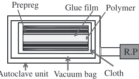
As shown in Fig. 2, the volume of sandwich structural composites of CFRP/PC/CFRP of PC core (Takiron Ltd., Tokyo) covered with carbon fiber cross textile reinforced
epoxy thin sheets at both side surfaces (CFRP, 0.25 mm thickness, TR3110-331MP epoxy/CF, Mitsubishi Rayon Ltd., Tokyo) was 2240 mm3. Since adhesive force between
PC and CFRP is not high, glue film (NB-102HC-50-0.06, GH-Craft Ltd., Tokyo) was used to make the composites.
As shown in Fig. 3, the CFRP/PC/CFRP laminate sample was pre-preged. Volume fraction, Vfof carbonfiber and PC
core were 12 and 88 vol%, respectively. In the CFRP sheet, Vf of carbon fiber was 60%. Making composites was
performed by autoclave molding in vacuum under 1 Pa for 2 h at 403 K.
Since the bundle direction was the longitudinal direction, a high unidirectional strength perpendicular to the sheet plane can be expected.
2.2 Impact test and its condition at high and low temperatures
In order to evaluate the impact fracture toughness, the Charpy impact values of the CFRP/PC/CFRP and CFRP samples with and without heating and cooling were measured using a standard impact fracture energy measurement system (Shimadzu Corporation No. 51735) (JIS K 7077).22) CFRP sample sizes were a 12-ply laminate with dimensions 80©10©2.0 mm. The impact fracture energy (E) was expressed by the following equation.2226)
E¼WR½ðcos¢cos¡Þ
ðcos¡0cos¡Þð¡þ¢Þ=ð¡þ¡0Þ ð3Þ
Here, E,W,R, ¢, ¡and¡Bwere impact fracture energy (J), hammer weight (8.43 N), length (m) of hammer weight point from rolling center (0.21 m), the maximum angle after impact, start angle before impact (132°), and the maximum Fig. 2 Schematic diagram of sandwich structural composite of CFRP/PC/
CFRP.
Prepreg
R.P
Autoclave unit Vacuum bag Cloth Polymer Glue film
[image:2.595.96.242.70.111.2] [image:2.595.349.500.71.231.2] [image:2.595.356.500.284.366.2]angle of the blank test (Radians), respectively. The Charpy impact value (auc: kJ m¹2) was expressed by the following
equation.22)
auc¼E=ðbtÞ 103 ð4Þ
Here, E,b (=10«0.2 mm) andt(=2.8 mm) were impact fracture energy (J), sample width (mm) and span distance (sample thickness, mm), respectively. The distance between supporting points was 40 mm.
The samples were cooled by liquid nitrogen and ethanol with dry ice and heated by heat gun (brawer). The impact test was performed, when the sample temperature was constant.
3. Results
3.1 Impact values of CFRP/PC/CFRP
Impact values (auc) of sandwich structural composites
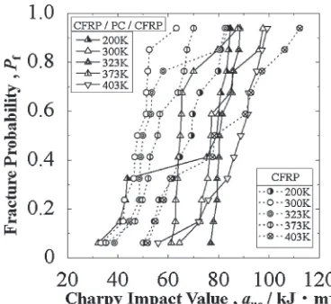
(CFRP/PC/CFRP) of polycarbonate (PC) cores covered with thin sheets of carbon fiber cross textile reinforced epoxy (CFRP) at both side surfaces have been obtained. Figure 4 shows changes in Charpy impact value of CFRP/PC/CFRP against fracture probability (Pf) at each testing temperature
from 200 to 403 K below the glass transition temperature of PC (Tg=422 K)16)and epoxy (Tg=403 K).
Results show overall, the CFRP/PC/CFRP has higher auc
values than the CFRP. Note Fig. 4 shows the auc at room
temperature (300 K) of CFRP/PC/CFRP (77 kJ m¹2) is
approximately 64% higher than that of CFRP sheet (47 kJ m¹2) at mid-P
f of 0.50. Moreover, the auc values of
CFRP/PC/CFRP at all fracture probabilities (Pf) at 300, 323
and 373 K as well as mid-Pfof 0.50 at each temperature from
200 to 403 K are apparently higher than that of the CFRP. Although auc the CFRP/PC/CFRP is reduced below the
CFRP for 200 and 403 K below Pf=0.40 and above Pf=
0.60 to 0.70, respectively, auc of the CFRP/PC/CFRP
improves over the CFRP at auc above Pf=0.40 and below
Pf=0.60 to 0.70, respectively. Both the CFRP/PC/CFRP,
and CFRP sheet have the highest aucat 403 K.
Theaucof CFRP/PC/CFRP heated at water boiling point
of 373 K is always lower than that at 300 K at eachPfvalue
from 0.12 to 0.94; at 323 K the aucvalues at lower Pffrom
0.06 to 0.78 of CFRP/PC/CFRP are mostly higher than that at 300 K. At 403 K all auc values between Pf from 0.12 to
0.94 of CFRP/PC/CFRP are higher than that at 300 K. When the CFRP/PC/CFRP sample is cooled at nitrogen boiling point of 77 K, delamination occurs before the impact test. Thus,auccannot be obtained at 77 K.
The higheraucof CFRP/PC/CFRP at 200 K is found from
77 to 83 kJ m¹2at higherPf of more than 0.41, whereas the
loweraucof CFRP/PC/CFRP at 200 K is distributed from 32
to 42 kJ m¹2at lowerP
fof less than 0.41. Theaucof CFRP/
PC/CFRP cooled at low temperature of 200 K is higher than that at 300 K at mid-Pfvalues of 0.50 and 0.59, although it is
lower than that at low and highPf values of less than 0.41
and more than 0.58, respectively.
3.2 Optical observation of fractured CFRP/PC/CFRP at each testing temperature
Figure 5 shows photographs of fractured CFRP/PC/CFRP samples at the testing temperatures from 200 to 403 K showing fracture occurred with delamination of surface CFRP thin sheets within the totalPfrange.
Note fracture cannot be observed in the PC core at all testing temperatures. Heating from 323 to 403 K results in remarkable bending plastic deformation of the core, whereas cooling from 300 to 200 K results in bending elastic deformation of the core at eachPf.
Fracture and/or surface damage of impacted CFRP sheets occur at mid-Pfof 0.50 from 200 to 403 K; at mid- and high
Fig. 4 Changes in Charpy impact value (auc) of CFRP/PC/CFRP (solid lines) at each temperature against fracture probability (Pf), together with CFRP (dotted lines).
Pf=0.06
Pf=0.50
Pf=0.94
[image:3.595.74.258.69.238.2] [image:3.595.343.508.71.401.2]Pf at 373 K; and at each Pf at 323 and 403 K; although
fracture of the CFRP thin sheet at the tensile surface side of the sample heated at 403 K occurs at highPfof 0.94. Both PC
core bending plastic deformation and delamination between core and CFRP sheet at impacted and tensile sides are found in the sample of eachPf heated at 373 K.
4. Discussion
4.1 Fracture mode dependent impact value
Up to now, there has been no or very little research on Charpy impact value (auc) of composite sandwich structures.
However, there is extensive research on point impact311)and
point impact followed by CAI,8,9) to evaluate strength of
damaged aerospace materials. Point impact followed by CAI is very different than Charpy impact. In Charpy impact, a thin specimen (Fig. 5) is impacted across its entire cross-section, whereas in point impact the center of a wider specimen is impacted from a point source. Since Charpy is an easy and economical method, we will compare fracture modes of this study with those of point impact mentioned previously: core crushing, core cracking, delamination in the impacted face sheet, matrix cracking, andfiber breakage in the face sheets.10)
Different than point impact, Charpy impacted specimens in Table 1 show no evidence of core crushing or cracking, and no delamination within the impacted face sheet since it is only one ply. Similar to point impact, there appears to be matrix cracking andfiber breakage from the Charpy impact tests.
Specifically, based on the results in Figs. 4 and 5, the fracture mode, impact value (kJ m¹2) and reduced
delamina-tion area against sheet sample area at low, mid- and high fracture probability (Pf)=(0.06, 0.50 and 0.94) at each
impact test temperature of 200, 300, 323, 373 and 403 K are summarized in Table 1. Fracture mode is explained by a delamination between PC core and surface CFRP thin sheets, bending plastic deformation of the PC core and CFRP fracture. Table 1 and Fig. 5 show the PC is a strong core because there is no evidence of core crushing or cracking. However overall, there is delamination in the impacted and back face sheets indicating a stronger bonding agent would probably increaseaucfurther.
Although the CFRP thin sheet fracture at tensile surface side occurs with negligible delamination area, the bending plastic deformation of the PC core of the sample with the highestauc(99.3 kJ m¹2at highPfof 0.94 under the highest
test temperature of 403 K in Table 1) occurs. The plastic deformation of PC is one of the dominant factors to relax the impact energy.
On the contrary, the sample with 2nd highest auc
(97.6 kJ m¹2 at high Pf of 0.94 at room temperature of
300 K in Table 1) exhibits the delamination fracture at both interfaces between elastic deformed PC core and CFRP sheets (see Table 1). The delamination is also one of the dominant factors to relax the impact energy.
4.2 Weibull coefficient (n) of CFRP/PC/CFRP
The Weibull coefficient (n) is one of the standard and traditional factors to compare with many other structural materials.2225) When a
uc is the measured Charpy impact
value and a constant, the fracture probability (Pf) as a
function of the risk of rupture (auc/ao) is expressed by the
following equation.26)
Pf ¼1exp½ðauc=aoÞn ð5Þ
The linear relationship can be obtained as the following equation.
lnðlnð1PfÞÞ ¼nlnaucnlnao ð6Þ Figure 6 shows Weibull plots of CFRP/PC/CFRP at each temperature. The n value corresponds to the slopes of the relationships of Weibull plots.
Figure 7 shows the change in Weibull coefficient, n of CFRP/PC/CFRP against testing temperature. The high n values, which are higher than those at high and low temperatures of 200 and 403 K, are obtained from 300 to 373 K. The highest n value of 22 related to reliability with low experimental error of CFRP/PC/CFRP is obtained at 323 K.
4.3 Temperature dependent lowest impact value of CFRP/PC/CFRP
On the other hand, since the experimental impact values at lower Pf value have largely deviated from the linear
relationship (see Fig. 4), the practical impact value at lowPf
value cannot be estimated.
Pf Impact test temperature
200 300 323 373 403
0.06 ① ① ①
32.2 (0.5) 64.4 (1.0) 76.9 (0.5) 61.2 (2.0) 56.0 (0.5)
0.50 ① ① ①
79.2 (0.5) 77.0 (1.5) 80.3 (0.5) 64.8 (1.0) 88.8 (0.5)
0.94 ① ① ①
84.6 (1.0) 97.6 (1.0) 88.4 (0.5) 87.6 (1.5) 99.3 (0.0)
[image:4.595.336.505.71.209.2] [image:4.595.48.292.155.263.2]If the statistical equation is assumed to be applicable to the measured auc value, the Pf value depends on the risk of
rupture ([auc¹as]/aIII).2225,27)
Pf ¼1exp½ð½aucas=aIIIÞm ð7Þ
In predicting the required impact value of the new structural material, the lowest impact value (as), the
coefficient (m) and constant (aIII) are key parameters.
The aIII is the auc value at Pf of 0.632 when the term
(ln[¹ln(1¹Pf)]) is zero.
When thePfvalue is equal to zero, theaucvalue is defined
as theasvalue. When a correlation coefficient (F) of eq. (5)
shows the maximum value, the potential (ea
s) value can be
determined to be the lowest impact value (as) applied.
Figure 8 shows changes in the F value with respect to the
ea
s value. Since the F values are from 0.92 to 0.97 in
Fig. 8, the relationships in Fig. 9 exhibit the high linearity. Figure 9 shows linear relationships between ln(auc¹as) and
ln[¹ln(1¹Pf)] for CFRP/PC/CFRP at each temperature.
The values ofaIIIandmare determined by the least squares
bestfit method. Themvalue is estimated by the slope of the relationship as a function of the as value. Figure 10 shows
changes in experimental impact values (auc) at low Pf of
0.06 ( ) and the lowest impact values ( :as=aucatPf=0)
of CFRP/PC/CFRP plotted against temperature. Based on the results, the high as values, which are higher than those
(27 and zero kJ m¹2) at high and low temperatures of 200
and 403 K, are obtained from 300 to 373 K. The highestas
(76 kJ m¹2) was found at 323 K.
4.4 Impact values of CFRP/PC/CFRP at room temper-ature
Figure 4 also shows changes in impact value of CFRP (dotted lines) against Pf at each temperature from 200 to
403 K,15) together with CFRP/PC/CFRP (solid lines).
Although the volume fraction of carbon fiber (12%) of CFRP/PC/CFRP is much smaller than that (60%) of CFRP, the auc of CFRP/PC/CFRP at room temperature (300 K) is
approximately 64%higher than that of CFRP sheet at 300 K. This is caused by not only high impact value (84 kJ m¹2) of
PC, but could probably also occur in aviation parts during
flight by microcrack toughening under load. Although the fracture cannot be observed in the PC core at testing temperature of 300 K (see Fig. 5), the delamination occurs at interface between PC core and both CFRP thin sheets to relax the impact force instead of the simple fracture of CFRP.4)
4.5 Impact values of CFRP/PC/CFRP at low temper-atures of 77 to 200 K
The surface CFRP delamination occurs in the CFRP/PC/ CFRP cooled at nitrogen boiling point of 77 K before impact test. The linear coefficient of thermal expansion (CTE) values of PC, epoxy resins and typical carbonfiber (PAN M40) are Fig. 7 Changes in Weibull coefficient of CFRP/PC/CFRP at each
temperature.
Fig. 8 Changes in theFvalue of CFRP/PC/CFRP with respect to theeas value.
[image:5.595.101.237.67.199.2]Fig. 9 Liner relationships between ln(auc¹as) and ln[¹ln(1¹Pf)] for CFRP/PC/CFRP at each temperature.
[image:5.595.331.513.73.226.2] [image:5.595.80.255.244.419.2] [image:5.595.349.504.269.427.2]on the carbonfiber from epoxy resin occurs at the interface and prevents fiber pullout, resulting in enhancement of impact value of CFRP.
At 200 K (see Fig. 4), the higher aucof CFRP/PC/CFRP
is found from 77 to 83 kJ m¹2atP
f>0.40 and is higher than
that of CFRP. This can be explained by fracture not being observed in the PC core at highaucat 200 K.
On the other hand, although the lower aucof CFRP/PC/
CFRP at 200 K is distributed from 32 to 42 kJ m¹2 at
Pf<0.40, they are approximately equal to that of simple
fractured CFRP at 200 K.4) Since the delamination is the
simple dominant factor to fracture the samples at 200 K and easily occurs (see Fig. 5), the impact force is relaxed thus, it can be explained.
4.6 Impact values of CFRP/PC/CFRP at high temper-ature
The auc of CFRP/PC/CFRP heated at 403 K, which is
mostly higher than that at higherPfvalues from 0.12 to 0.94
at 300 K, is also higher than that at lowerPfof less than 0.6
of CFRP at 403 K.
As shown in Fig. 5, the PC core bending and small delamination area as well as the CFRP thin sheet fracture at tensile surface side occur in the sample heated at 403 K. Since the heating near glass transition temperature of epoxy resin (Tg=398 K)22) enhances the fluidity, it easily relaxes
the impact force by energy loss of polymer deformation. Thus, the high impact value induced by heating is explained, as shown in Fig. 4. Theaucof CFRP/PC/CFRP heated at the
water boiling point of 373 K, which is always lower than that at 300 K at eachPfvalue from 0.06 to 0.94, is always higher
than that of the CFRP at 373 K. When the heating reduces the elasticity and compressive stress to prevent the pull-out, it probably reduces the resistance to deformation, resulting in the impact value drop. As shown in Fig. 5, the PC core bending and broad area peeling as well as the CFRP thin sheet fracture at the impacted surface side occurs in the sample heated at 373 K. Although theaucat 373 K of CFRP/
PC/CFRP is always higher than that of CFRP, the lower impact value induced by heating at 373 K is explained, as shown in Fig. 4.
Moreover, the auc of CFRP/PC/CFRP heated at 323 K,
which is mostly higher than that at 300 K at lowerPfvalues
from 0.06 to 0.78, is always higher than that of CFRP at 323 K. The PC core undergoes bending with delamination on the tensile-side CFRP thin sheet at testing temperature of 323 K (see Fig. 5) to relax the impact force instead of the simple fracture of CFRP.15)
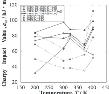
4.7 Temperature dependent impact value of CFRP/PC/ CFRP
Figure 11 shows changes in Charpy impact value of the sandwich structure CFRP/PC/CFRP at low, mid- and high
Pf of 0.06, 0.5 and 0.94 against each testing temperature,
together with CFRP samples. Note the auc values of the
CFRP/PC/CFRP (74+/¹11 kJ m¹2at mid-Pfof 0.50 from
T=200 to 403 K) are higher than those (57+/¹11 kJ m¹2) of the CFRP. The auc values of 55+/¹23 and 92+/¹
8 kJ m¹2 at low and high Pf of 0.06 and 0.94, respectively
from T=200 to 403 K of CFRP/PC/CFRP are also higher than those (43+/¹10 and 87+/¹25 kJ m¹2) of the CFRP.
The higheraucat RT and mid-Pfof 0.5 of CFRP/PC/CFRP
can be mainly explained by the highaucof PC (84 kJ m¹2)18)
rather than that of CFRP (40 kJ m¹2).
Moreover, theaIIIvalues at 403 K are higher than those at
room temperature (300 K).
In addition, at the time of this study the cost of CFRP/PC/ CFRP was 40% lower than that of CFRP. Since the use of PC resin as the core enhanced the safety design with low cost, the sandwich structural composites of CFRP/PC/CFRP can be mostly used for daily articles.
5. Conclusions
Impact values (auc) of sandwich structural composites
(CFRP/PC/CFRP) of polycarbonate (PC) cores covered with one ply sheets of carbonfiber cross textile reinforced epoxy (CFRP) at both side surfaces were obtained at different temperatures from 200 to 403 K below the glass transition temperature of PC. The auc of CFRP/PC/CFRP were
compared with a 2.0 mm thick 12-ply CFRP laminate. Fracture mode was characterized by delamination between PC core and the surface CFRP thin sheets, bending plastic deformation of the PC, and fracture of the CFRP ply.
(1) Results showed overall, the CFRP/PC/CFRP had higher auc than the CFRP at each fracture probability
(Pf) from 300 to 373 K except at 200 K with lowPfand
403 K with high Pf. Although the volume fraction of
carbon fiber (12%) of CFRP/PC/CFRP was much smaller than that (60%) of CFRP, theaucof CFRP/PC/
[image:6.595.334.516.76.234.2]interface between PC core and both CFRP thin sheets to relax the impact force, instead of the simple fracture of CFRP.
(2) The auc values of CFRP/PC/CFRP at each fracture
probability (Pf) at 300 K as well as mid-Pf of 0.50 at
each temperature from 200 to 403 K were apparently higher than that of CFRP. Since the price of CFRP was higher than that of core PC, the cost of CFRP/PC/ CFRP was 40%lower than that of CFRP at the time of this study. Also, since the use of PC resin as the core enhanced the safety design at low cost, practical use of sandwich structural composites of CFRP/PC/CFRP is possible.
(3) When the CFRP/PC/CFRP sample was cooled at nitrogen boiling point of 77 K, delamination occurred before the impact test. Thus, auccould not be obtained
at 77 K.
(4) The higheraucof CFRP/PC/CFRP at 200 K was found
from 77 to 83 kJ m¹2atP
f>0.40, whereas the lowerauc
of CFRP/PC/CFRP at 200 K was distributed from 32 to 42 kJ m¹2at Pf<0.40 because of delamination of the
CFRP thin sheets. Moreover, theaucat mid-Pfvalues of
0.50 and 0.60 of CFRP/PC/CFRP cooled at 200 K were higher than those at 300 K. Since delamination easily occurs, the impact force was relaxed.
(5) The auc of CFRP/PC/CFRP heated at 323 K was
mostly higher than that at 300 K at lowerPfvalues from
0.06 to 0.78. It was always higher than that of CFRP at 323 K. The PC underwent bending with delamination on the tensile-side CFRP thin sheet at 323 K to relax the impact force.
(6) Although the auc of CFRP/PC/CFRP heated at water
boiling point of 373 K was always lower than that at 300 K at eachPfvalue from 0.06 to 0.94, it was always
higher than that of CFRP at 373 K. When the heating reduced the elasticity and compressive stress to prevent the pull-out, it probably reduced the resistance to deformation, resulting in impact value drop.
(7) The auc of CFRP/PC/CFRP heated at 403 K was
mostly higher than that at 300 K at higher Pf values
from 0.12 to 0.94 and was also higher than that of the CFRP at lowerPfof less than 0.60 at 403 K. Since the
heating near glass transition temperature of epoxy resin enhanced thefluidity, it easily relaxed the impact force by energy loss of polymer deformation, resulting in the high impact value.
(8) Based on the results and Weibull equations with two and three parameters, both Weibull coefficient (n) and the limited impact value (as) at 300 to 373 K were
higher than those at 200 and 403 K. The highest as
(76 kJ m¹2) andn(22) were found at 323 K.
(9) We do not claim the Charpy test to be a substitute for point impact followed by compression after impact (CAI). However, Charpy impact method with hammer hitting velocity of ³1.74 m s¹1 could possibly be used as an inexpensive preliminary evaluation to screen candidate materials to later test with indentation or projectile followed by CAI. Up to now, there has been no or very little research on Charpy impact value (auc)
of composite sandwich structures. Hence, Charpy may
give a rough or better estimation of which materials and what temperatures a projectile such as bird strike, volcanic rock or hailstone will cause the most damage.
Acknowledgement
We would like to extend our sincere gratitude to Mr. Yoshihide Ebihara M.S., Dr. Masae Kanda, and Dr. Keisuke Iwata for their great assistance.
REFERENCES
1) D. K. Thomas: Plastics Rubber Int.8(1983) 5357. 2) M. B. Dowell: Plastics Eng.33(1977) 3132. 3) ASTM D 6264-98 (1998).
4) K. Imielińska, L. Guillaumat, R. Wojtyra and M. Castaings:Compos: Part B39(2008) 10341041.
5) A. S. Vaidya, U. K. Vaidya and N. Uddin:Mater. Sci. Eng. A472
(2008) 5258.
6) O. S. David-West, D. H. Nash and W. M. Banks:Compos. Struct.83
(2008) 247258.
7) L. Aktay, A. F. Johnson and M. Holzapfel:Comput. Mater. Sci.32
(2005) 252260.
8) K. Komai, K. Minoshima, K. Tanaka and K. Nakaike: 12th Int. Conference on Composite Materials, Paris, (1999) paper 1286, pp. 110.
9) M. Aktaş, R. Karakuzu and Y. Arman:Compos. Struct.89(2009) 7782. 10) H. M. Wen, T. Y. Reddy, S. R. Reid and P. D. Shoden:Key Eng. Mater.
141143(1998) 501552.
11) S.-L. Gao and J.-K. Kim:Compos. Part A Appl. Sci. Manuf.32(2001) 775785.
12) V. Kostopoulos, A. Baltopoulos, P. Karapappas, A. Vavouliotis and A. Paipetis:Compos. Sci. Tech.70(2010) 553563.
13) J. D. Splett, H. K. Iyer, C.-M. Wang and C. N. McCowan:National Institute of Standards and Technology (NIST) Recommended Practice Guide, Computing Uncertainty for Charpy Impact Test Machine Test Results; Special publication 960-18, US Department of Commerce: Boulder, Colorado (2008) pp. 2729.
14) T. Yamamoto, S. Nanba, Y. Ebihara and Y. Nishi:J. Jpn. Inst. Metals74
(2010) 127130.
15) Y. Nishi, N. Tsuchikura, S. Nanba, T. Yamamoto and K. Iwata: submitted.
16) Q. Lin and A. F. Yee:J. Mater. Sci.32(1997) 39613970.
17) Macmilan’s Chemical and Physical Data, Arthur M. James & Mary P. Lord (1986) pp. 398399.
18) M. Bauccio (Ed.): ASM Engineered Materials Reference Book, 2nd Edition, (Materials Park, Ohio: ASM International, 1994) p. 410. 19) J. M. Pérez, J. L. Vilas, J. M. Laza, S. Arnáiz, F. Mijangos, E. Bilbao,
M. Rodríguez and L.M. León:J. Mater. Process. Technol.210(2010) 727733.
20) Japanese Industrial Standards Committee: JIS K7077 (1991). 21) P. M. Schubel, J.-J. Luo and I. M. Daniel:Compos. Part A Appl. Sci.
Manuf.38(2007) 10511057.
22) Y. Nishi, K. Inoue and M. Salvia:Mater. Trans.47(2006) 28462851. 23) Y. Nishi, H. Takei, K. Iwata, A. Vautrin and M. Salvia:Mater. Trans.50
(2009) 28262832.
24) H. Takei, K. Iwata, M. Salvia, A. Vautrin and Y. Nishi:Mater. Trans.51
(2010) 22592265.
25) Y. Nishi, H. Kobayashi and M. Salvia:Mater. Trans.48(2007) 1924 1927.
26) W. Weibull:Ingeniörs vetenskaps akademien, nr. 151 (Generalstabens litografiska anstalts förlag, Stockholm, 1939) pp. 1214.
27) W. Weibull:Ingeniors veterskaps akademien, nr. 153 (Generalstabens litografiska anstalts forlag, Stockholm, 1939) pp. 1622.
28) A. M. James and M. P. Lord:Macmillan’s Chemical and Physical Data, London and Basingstoke, (The Macmillan Press, Ltd. 1992) pp. 398 399.

![Fig. 9Liner relationships between ln(auc ¹ as) and ln[¹ln(1 ¹ Pf )] forCFRP/PC/CFRP at each temperature.](https://thumb-us.123doks.com/thumbv2/123dok_us/325491.531108/5.595.80.255.244.419/fig-liner-relationships-auc-pf-forcfrp-cfrp-temperature.webp)