EVALUATION OF THE UNSTEADY E F F E C T S FOR A CLASS OF WIND TURBINES
T h e s i s by J e a n - Luc C o r n e t
In P a r t i a l Fulfillment of t h e R e q u i r e m e n t s f o r t h e D e g r e e of
Doctor of Philosophy
California Institute of Technology Pasadena, California
1984
ii
ACKNOWLEDGMENT
I would like to e x p r e s s m y s i n c e r e appreciation to P r o f e s s o r Theodore Yao- Tsu Wu, whose guidance, help and encouragement w e r e indispensable to the successful completion of this work. F o r his
patience and understanding, I a m m o s t sincerely grateful.
Special thanks a r e a l s o due to Dr. George
T.
Yates for hisfriendship and f o r his interesting discussions on some of the theoretical issues. His help in the final correction of this manuscript was greatly appreciated.
I a m deeply indebted to Miss Helen B u r r u s , who courageously undertook the laborious t a s k of typing this t h e s i s , f o r h e r excellent work and helpful suggestions.
I gratefully acknowledge financial support f r o m the F r e n c h "MinistBre de s affair e s 6trangbres ' I , the National Science Foundation, the Office of Naval R e s e a r c h and the California Institute of Technology.
Finally, the deepest appreciation of a l l goes to my wife, Arlette, and my daughter, Sandrine, who have silently borne the
iii ABSTRACT
An investigation of a c l a s s of v e r t i c a l a x i s wind turbines i s c a r r i e d out with the unsteady effects due to the rotating blade motion fully taken into account. The work i s composed of two parts.
In
p a r t one, a hydromechanical theory i s developed which pro- ceeds f r o m the point of view of unsteady airfoil theory. A rotor com- prised of a single blade i s used and a two-dimensional analysis i sapplied to a c r o s s section of the r o t o r in the limiting mode of operation wherein U
<<
GR. Use of linearized theory and of the acceleration potential allows the problem to be e x p r e s s e d in t e r m s of a Riemann- Hilbert boundary value problem. The method of c h a r a c t e r i s t i c s i s used to solve f o r the remaining unknown function. A uniformly valid f i r s t o r d e r solution i s obtained in closed f o r m after some approximation based on neglecting the variations in the c u r v a t u r e of the path.Explicit expressions of the instantaneous f o r c e s and moments acting on the blade a r e given and t h e total energy lost by the fluid and the total power input t o the turbine a r e determined.
-
iv
TABLE OF CONTENTS
PART Page
I EVALUATION OF THE UNSTEADY EFFECTS FOR A C U S S OF VERTICAL AXIS WIND TURBINES
1. Introduction
2 . General Formulation
3. Kinematics of the motion
3 . 1 The coordinate systems 3 . 2 Trajectory
3 . 3 Boundary conditions 3 . 4 The osculating case
3. 5 Linearized boundary conditions 4. Dynamics
4. 1 The Bernoulli equation 4. 2 The acceleration potential
4.3 Formulation in the complex plane 4 . 4 A Riemann-Hilbert problem
4. 5 Solution of the Riemann-Hilbert problem 4. 6 Integration of the Euler equation along i t s
c h a r a c t e r istics 27
4.
6.
1 The c h a r a c t e r i s t i c lines 28 4. 6.2 Integration along the c h a r a c t e r i s t i c s 30 4. 6.3 Simplified e x p r e s s ion of thecharacteristic equation 3 2
4.
7
Development of the integral equation f o rv
TABLE O F CONTENTS (cont'd)
PART
4.8 Approximated c h a r a c t e r i s t i c lines 4.
9
Solution for a O ( 7 )5. F o r c e s
5. 1 The p r e s s u r e force 5 . 2 The leading edge suction 5 . 3 T h e t o t a l f o r c e
5 . 4 Moments 6. Power a n d e n e r g y
6. 1 Kinetic energy 6.2 Power output 6.3 Energy balance 7. Conclusion
Appendix A Appendix B Appendix C Appendix D References Figures
I
3
AN APPROACH TO THE PROBLEM OF WAKE CROSSING1. Introduction
2. General formulation
3. Ixnpulsive crossing of a vortex sheet
Page 3 5 39 42 42 43 45 46 46 46 48 49 5 0
5 2
5 5
6 4
66
vi
TABLE OF CONTENTS (cont'd)
PART
4. Continuous crossing of a vortex sheet 4. 1 Green's Integral Theorem
4. 2 Reciprocity relation for unsteady incompressible potential flow 4 . 3 Two-dimensional case
4. 4 P r e s s u r e and velocity relations
4. 5 Application to the crossing of a wake by a wing
4. 6 Evaluation of O' ( T ) 4. 7 Solution for the lift 4.8 Evaluation of A(UoT) 5. Conclusion
Appendix A
Appendix B References Tables F i g u r e s
Page
96
LIST O F FIGURES
F igur e PART I
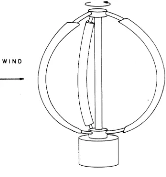
1 Initial design of the Darrieus rotor
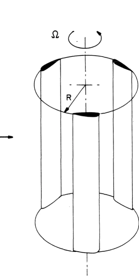
2 Simplified model of the Darrieus rotor used in the present investigation
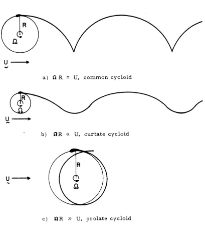
3 Trajectories of the blade in the fluid f r a m e of reference for different values of the tip speed to wind speed ratio. Only c a s e ( c ) is of interest for energy extraction purpose and is therefore investigated.
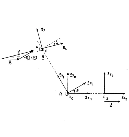
The coordinate systems comprising the structure f r a m e of reference (x
0' ) fixed with the
s t r u c t u r e of the turbine, t%e body f r a m e of r e f e r
-
ence (x, y ) moving with the blade and defined withzx
always parallel to the apparent flow velocityx,
and the fluid f r a m e of reference (x2, y2) moving with the undisturbed fluid a t infinity.
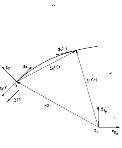
Description of the trajectory of the origin 0 in the fluid f r a m e of reference (xZ,y2).
Description of the blade in the body f r a m e of reference. The blade is represented by its t r a n s v e r s e displacement f r o m the x-axis h(x, t ) and the half chord is normalized to unity, with the blade extending f r o m x =
-
1 to x = t 1 along the x-axis.Representation of the contours Co and Cm defining the region D. Co encloses the blade and its wake and C, is a closed contour c i r - cumventing the point a t infinity.
Representation of the exact characteristic lines (1. 65) f o r two values of z :
-
z = O ,- -
-
z * 0.Page 7 3
Representation of the approximate characteristic lines (1.79). An expansion a t f i r s t o r d e r in E of (1. 79) is actually used to avoid coming back in the a r e a of strong disturbance around the leading edge.
-
-
-
Approximate characteristic line (1. 79)viii
LIST OF FIGURES (cont'd)
Figure PART I1
1 Description of the blade and the coordinate systems comprising the inertial f r a m e of reference (X, Y ) , stationary with the fluid, and the body frame of reference ( x , y ) , translating along the X-axis with velocity
U . The blade extends from x = -1 to x
=
t l along the x-axis and the wake extends from x = + l to X = 0.Vorticity distribution on a wing induced by a point vortex placed at various distances from the trailing edge on the wake.
Description of the vortex sheet in the case of impulsive crossing of a vortex sheet by a wing. The vortex sheet crosses the X-axis at X
=
0 and is inclined with an angle Bfrom the X-axis.The wing is translating along the X-axis with velocity - U and has an angle of attack a 1 prior to the crossing and a 2 after the
crossing. U2 represents the apparent flow velocity after the crossing.
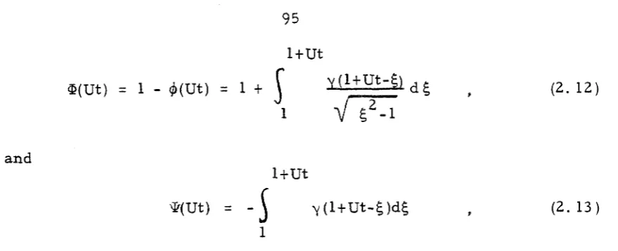
Wagner's function (@ (Ut)). S e a r ' s function QfUt)).
Description of the reference system used in the derivation of the reverse flow relations.
The plan form P represents the space occupied by the blade in the (x, t ) plane. Description of the coordinate systems in the
(x, t ) plane for both the direct and reverse motion. (xl, t l ) is associated with the direct motion and (x2, t 2 ) with the r e v e r s e motion.
The vortex sheet
Tl
is placed at x l = 0. Two cases a r e represented.Description of the two vortex sheets
6
and'-C 'U
y 2 . y 2 is chosen with u =
-u
y , and"Y-,
Lambda function A(Ut).
PART I
1 1. Introduction
Although Wind Energy was one of the f i r s t energy r e s o u r c e s to be harnessed by man, and was extensively used by most of the known civilizations for propulsion o r energy extraction up to the beginning of the industrial e r a , it s e e m s to have been rediscovered only a few decades ago. Consequently the development of advanced theories on extraction of energy f r o m the wind is only beginning. Horizontal axis wind turbines have benefited directly f r o m the extensive investigations c a r r i e d out for airplane propellers, a s illustrated by the works of Glauert [I], Theodor sen [2] and Goldstein [3], and f r o m the experiments
on propeller type windmills performed in the past [4], [5]. Vertical axis wind turbines have only recently been studied and the theories developed for them a r e quite f a r f r o m matching the sophisticated vortex theories currently used for horizontal axis machines.
Vertical axis wind turbines offer s e v e r a l advantages over m o r e conventional wind turbines : they do not require an initial orientation into the wind, can conveniently have the power generator located at the ground level and may even eliminate the need for a supporting tower. These advantages should make possible the development of a lighter and cheaper structure, and thus make the vertical axis wind turbine a p r i m a r y candidate in wind energy technology.
2
Aerodynamics of the Darrieus rotor and models f o r performance prediction have since been formulated by Templin [8], Strickland [9], Shankar [lo], Wilson and Lissaman [1 l], Holme [12] and others. Except for the work of Holme
,
a l l these formulations a r e based on variations of the actuator disk theory developed by Betz [13] for the horizontal axis windmill. In this theory the momentum flux through the s t r e a m tube enclosing the turbine i s equated to the time averaged force on the blade elements. Templin [8] used a single s t r e a m tube and took the flow velocity a t the rotor to be the arithmetic mean of the velocity f a r in front and the velocity f a r behind the turbine. Multiples t r e a m tubes have been used to account for the variation of the velocity a c r o s s the s t r e a m tube, [9], [lo], [ I I], but only Holme [12] considered the variations of flow velocity in both the streamwise and t r a n s v e r s e directions. Common to a l l these formulations is the assumption of quasi-steady motion in computing the f o r c e s acting on the blade
elementq thereby neglecting the perturbation velocities induced by the wake, the added m a s s of the blades,and m o r e significantly the varia- tions of the leading edge suction induced by the unsteady flow. At the low values of the reduced frequency usually encountered in studies of a Darrieus rotor, variations of the lift due to the unsteady effects a r e known to be small; however the leading edge suction variations a r e much l a r g e r and since a vertical axis wind turbine derives its torque f r o m the thrust acting on the blade elements, these variations may prove to be of significant importance. Other effects neglected in these previous investigations include the s t r e a m curvature effects, the interaction of the r e a r blades with the vortex wake shed f r o m the
3
The purpose of the p r e s e n t work is to develop a two-dimension- a l model f o r a general c l a s s of v e r t i c a l axis wind turbines. The
investigation proceeds f r o m the point of view of unsteady airfoil theory and adopts many of the ideas developed by Wu [14], [15], [16] in his study of the motion of a heaving and pitching airfoil. The contribution of the unsteady effects on the power extraction capability of a turbine a r e fully evaluated, including the kinetic energy imparted to the fluid, hence lost, by the blades. This should make feasible the maximization of the mechanical efficiency of a turbine by a proper optimization of the blade motion. In addition this model could be used with some elements of momentum theory to provide a better approximation of the maximum power cseffieient of a turbine than i s now available. The basic theory i s a l s o applicable, with some change of p a r a m e t e r s , to a
large c l a s s of cycloidal propellers used in naval architecture
(Schneider propellers). These propellers a r e lift oriented devices p r i m a r l y intended for m a r i n e vehicles operating in r e s t r i c t e d waters where their ability to produce thrust in any direction greatly enhances
4
2. General Formulation
Ln the present investigation we a s s u m e the fluid to be incom- pressible and inviscid. The effects of viscosity a r e only implicitly
inferred in invoking the Kutta condition and in turn in the formation of vortex wakes behind the blades. No fluid s ingularities a r e allowed outside this wake and the flow is irrotational and has a scalar potential.
The rotor to be investigated consists of a number of high aspect-ratio blades, of half chord c , symmetrical in shape and of constant c r o s s section along the span (fig. 2). The blades a r e placed a t regular intervals along the generators of a cylinder of radius R and rotate about the cylindrical axis with angular velocity !2
.
The rotor is placed in a flow having a constant velocity U a t infinity p e r - pendicular to the rotor axis. A c r o s s section of the rotor is taken a t mid span and a two-dimensional analysis is applied. Due to the high aspect-ratio of the blades this approximation is expected to providegood quantitative results. -4 rotor composed of a single blade is
investigated, but the results can be extended to multi bladed systems if the mutual interference between the blades is small. This assumption may s e e m r e s t r i c t i v e for the study of a wind energy extracting turbine, where the mutual interference between the blades is usually not small. However, since we restricted the analysis to lightly loaded turbines and a r e mainly interested in the influence of the unsteady effects on the overall performance of a turbine, it is a reasonable assumption.
5
i. Any movement of the wing relative to the apparent direc- tion of the incident flow is s m a l l so that the perturbation velocity components a r e s m a l l compared to the apparent velocity of the un- disturbed flow ;
ii. The Kutta condition holds, i. e.
,
both the p r e s s u r e and the velocity a r e required to be finite a t the trailing edge of the blade;...
111. The perturbation velocity is asymptotically zero a t infinity,
except in the region of the starting vortex and in the vortex wake. To satisfy these assumptions, s m a l l perturbations super
-
imposed on the "perfect" flow field of a flexible wing sliding on its trajectory a r e assumed. This simplification is applicable to a rigid blade if the curvature of the trajectory is s r l a l l coriipared to the bladechord, and puts some restrictions on the relative value of S2R and U: i. When !2
R
=
U, the trajectory of the blade (described in the fluid f r a m e of reference fixed with the fluid a t infinity) is a commoncycloid (fig. 3a). This c a s e is excluded since there exist isolated regions of large trajectory curvature.
ii. When il R
<<
U, the trajectory is a curtate cycloid and resembles a sinusoidal path (fig. 3b). In this c a s e the trajectory curvature i s small, even when the radius of the rotor is of the same o r d e r a s the chord of the blade. However, this c a s e is not very interesting for energy extraction since a large number of blades would be n e c e s s a r y to cover the sweep a r e a , and each blade allowed to6
and pitching blade in a flow of approximately constant velocity and has been solved by Wu [14].
iii. We a r e therefore left with the case R R
>)
U. The trajectory in this case is a prolate cycloid (fig. 3 c ) and looks like a circular path being slightly displaced after each revolution. This case is of muchgreater practical interest since the tip speed of the turbine is consid- erably higher than the wind velocity, which is a necessary condition f o r a significant amount of energy to be extracted. It is also relevant to the experiments done with rotors of fixed geometry where tip speeds
of the order of 3 times the wind velocity a r e necessary before any energy can be extracted [7]. The curvature of the path in this case is
1
of order
-
so that w e also require R>>
e for the curvature t o be Rsmall. This is also relevant to the current design of Darrieus rotor,
C
where the value of
-
is usually around 0. 1 or smaller.R
We therefore r e s t r i c t our investigation to the case
3 . Kinematics of the motion
3. 1 The coordinate systems
We define three frames of reference. The f i r s t one (x Yo) is the structure frame of reference. It is an i n e r t i a l f r a m e of reference, is fixed in space, its origin 0 is taken at the center of the rotor,
0
and the xo- axis points in the direction of the undisturbed flow velocity. The second frame of reference (x y ) rotates in the counterclock-
1' 1
f r a m e and they s h a r e the same origin. The third one (x, y ) is the body f r a m e of reference, its origin 0 is located along the yl- axis a t a distance
R
f r o m 0 and the x- axis is taken to be tangential to0
[image:16.549.60.466.289.624.2]the relative velocity of the undisturbed flow a t 0 , and points in the s a m e direction. The t h r e e f r a m e s of reference a r e represented in figure 4.
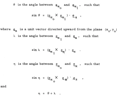
We introduce 8 , X and 7 a s the relative position angles of the t h r e e f r a m e s of reference, respectively (fig. 4), with a l l the angles assuming positive values in the counterclockwise directions.
6' is the angle between
%
and hl
,
such that
0
where
%
i s a unit vector directed upward f r o m the plane (xo, yo).X
i s the angle between e and e" x ' such that - 1
7 is the angle between e and e
,
such that-x rrx
0
and
T, =
e t x
.
and
where the subscript t denotes the time differentiation executed in the structure f r a m e of reference. We also define the two vectors
and by
and
We call the velocity of the undisturbed fluid in the structure f r a m e of reference, and the relative velocity of the undisturbed fluid a t the center of the body f r a m e of reference. The following relationships can then be written
The components of in (xl, y l ) a r e
V .
e-
= V sin 1 = - U sin 8,
9
so that the magnitude of is
2 2 2
V
=(U
+
i2R
t2URQ
cos 8 ) 1/2
9 and for the angleX
we have-sin 8 tan X =
cos
8
t R R / UThe body f r a m e of reference was chosen for the convenience of describing s m a l l perturbations. In this f r a m e of reference, with the variation of X prescribed by (1. 4), the undisturbed flow a t the origin 0 i s always parallel to the s a x i s and thus s m a l l movement of a blade about this mean position can be considered in the framework of linearized wing theory. It must be noted that in the body f r a m e of reference, a rotor of fixed geometry with respect to (x y ) would
1' 1 appear a s having an unsteady motion. F o r instance a blade which would be centered a t 0 with a fixed angle with r e s p e c t to e would
-XI
appear a s having a pure pitching motion.
3.
2 TrajectoryThe t r a j e c t o r y of the origin of the body f r a m e of reference in the fluid can be m o r e easily described with the help of a new f r a m e of reference ( x y ) which i s translating with the undisturbed fluid a t
2' 2
infinity, and will be r e f e r r e d to a s the fluid f r a m e of reference. Its axis a r e chosen with the same orientation a s ( x y ) and its origin
0' 0
O2 is chosen to coincide with O0 a t t = 0 and is translating in the positive x direction with speed
U
( s e e fig. 4).10
In the fluid frame of reference the origin 0 appears to be moving with the velocity - x ( t ) . We call s ( t ) the position vector of 0 in the fluid f r a m e of reference and g s ( t ) the unit vector tangent to the trajectory in the direction of motion (see fig. 5 ) . We can then write the following relations:
In the body frame of reference, the trajectory of the' origin 0 in space can be described by
x
(t', t ) = ( t ' )-
S ( t ),
-
c (1. 8 )where t is the present time and t 1 an arbitrary instant of time serving a s a parameter. Differentiating ,Xc(tt
,
t ) with respect to t ' and using (1. 7) and (1. 8 ) leads toa s
c(t', t )= -,V (t' )
11
We can decompose e ( t ' ) in the body f r a m e of reference, -s
using (1. 6), we obtain
CC
e ( t ' ) = - e ( t )
.
e ( t ' )=
-cos q (t', t ),
S1 -x -x
-
e ( t ' ) = - e y ( t ) . e ( t ' ) = - s i n ? ( t l , t )
,
2 -x
where
';;
(t', t ) is defined byThen, using (1. 5), (1.
9 )
and (1. l o ) , we can decompose X (t',t) into itsT
components in the body f r a m e of reference a s follows
Finally the curvature of the t r a j e c t o r y can be readily obtained f r o m (1. 10) and (1. 11) a s
12
3 . 3 Boundary conditions
The velocity expressed in the structure f r a m e of reference of a point fixed in the body f r a m e of reference is
where is the position vector of that point in the body f r a m e of reference. The perturbation velocity
E
and the total velocity8
,
expressed in the structure f r a m e of reference, a r e related by
Q = X t u ,
.
-
(1. 15) Further, in the body f r a m e of reference the velocity of the fluid isS = Q - s
.
-
Then, using (1.2), (1. 14) and (1. 15), we can express q a s
hr
The blade is represented in the body f r a m e of reference by its t r a n s v e r s e displacement f r o m the x-axis given by
y
=
h(x, t ).
A blade of chord 2 i s chosen, extending f r o m x =
-
1 to x = t 1, and the thickness of the blade i s neglected (fig.6).
13
where Q is the unit vector normal to the blade. In the body f r a m e of
reference we can express Q a s
and v a s --B
Therefore the kinematic boundary condition (1, 18) can be expressed a s
-
ah t q ( h - y ) = 0,
at
-
We finally define u and v to be the x-component and y-component of the perturbation velocity
,
Then, using (1. 17) and (1. 2 ) in (1. 19) we obtain
3 . 4 The osculating c a s e
14
This conclusion follows f r o m the absence of a mechanism by which the shear s t r e s s can be transmitted to the fluid in potential flow. Let's consider the trajectory of the leading edge 0 which i s followed in osculation by the motion of a flexible blade. The blade displacement f r o m the x-axis is then
The boundary condition (1. 20) can be written a s
Using the relation
and the expression for X ( t ' , t ) and Y ( t ' , t ) given by ( 1 . 12), the
C C
kinematic boundary condition reduces to
v
-
-
= tan 7 ( t i , t ).
u. where 4p is the velocity potential such that
=
'7 cp.If we a s s u m e that the fluid is initially a t r e s t and that any subsequent disturbance vanishes a t infinity, then on a l l the flow boundaries, including the vortex sheet, the following relationship is
satisfied.
2
The unique solution of the Laplace equation,
V
cp = 0, satisfying this boundary condition is cp =const; consequently2
=-
0 everywhere in the fluid and the proof is complete.To e n s u r e that only s m a l l disturbances a r e generated and imparted to the fluid, we must r e s t r i c t the blade to s m a l l displace- ments f r o m the trajectory of the origin 0 ; namely we require that
The function h (x, t ) defined in section 3 . 4 depends directly on the
C
value of the curvature of the path relative to the chord of the blade. F o r a blade of unit half chord, hc(x, t ) can be kept s m a l l by taking
which puts a limitation on the relative movements of the blade in the body f r a m e of reference.
3 . 5 Linearized boundary conditions
We now r e s t r i c t our analysis to the c a s e of s m a l l perturbations. In addition to the afore mentioned restrictions, we also assume the perturbation velocity to be small, a s well a s the derivatives of the blade displacement. The complete set of assumptions, with the half chord normalized to unity, is then
Recalling equation (1. 2 0 ) and neglecting the quadratic and higher order
t e r m s , we obtain the linearized boundary condition
We can s e e f r o m this equation that the fluid disturbance a r i s e s f r o m three sources:
ah which represents the disturbance induced by the r a t e
L-
at
17
ii. V(t) which is the disturbance induced by the displace- ment of the blade f r o m its z e r o "effective incidence" position;
iii. o (t)x which is the disturbance due to the rotation of the body coordinates with respect to the fixed s y s t e m and the rigidity of the blade.
4. Dynamics
4. 1 The Bernoulli equation
F o r the flow of an incompressible and inviscid fluid in the absence of external forces, the Euler equation of motion is
where the subscript o denotes the derivatives taken in an inertial f r a m e of reference. Assuming the flow to be irrotational in the inertial f r a m e of reference, a f i r s t integral of this equation can be obtained, the result of which is the Bernoulli equation which can be expressed in the present c a s e by
where cp r e p r e s e n t s the potential of the perturbation velocity
g ,
i. e.,1 2 P , - P t
Z
(Vq) tv_
( t ).
v q-
(2
x5 ) .
V q =at P
(1. 26)
In
deriving this expression, use has been made of (1. 2 ) , (1. 4 ) and the following relationshipsLinearizing (1. 26) by neglecting ( ~ p ) ' and developing it yields
This is our required linearized Bernoulli equation expressed in the body f r a m e of reference. This equation shows that variations of p r e s s u r e a r i s e f r o m t h r e e types of blade motion:
,
which represents the c l a s s of motion of the blade that1.
-
a t
appears to be unsteady in the body f r a m e of reference;
a
ii.. V
-
which depends on the rectilinear motion of the body axf r a m e of reference ;
a40
a"
-
x -),
which a r i s e s f r o m the angular motion ofiii. o(y
ax
ay the body f r a m e of reference.
The equation of continuity for an incompressible fluid is
Vo Q
-
= 0.
As usual in incompressible potential flow, this equation together with (1. 25) leads to the Laplace equation4. 2 The acceleration potential
A different expression of the Euler equation of motion can be found by defining a new function
which allow (1.23 ) to be expressed a s
dQ Y where % i s the acceleration vector of the local field,
2
=-
dto
G
is accordingly called the acceleration potential, and h a s the main advantage of being continuous everywhere in the fluid, except a c r o s s the blade itself. Especially noteworthy is its being continuous a c r o s s the vortex sheet shed f r o m the blade trailing edge, due to the continuity of the p r e s s u r e a c r o s s the wake.Unlike the velocity potential 9, which is always a harmonic function for irrotational motion of an incompressible fluid, (i. e . ,
2
Po 9 = 0). the acceleration potential is generally not harmonic. In
fact, taking the divergence of (1. 3 l ) , using (1. 2 4 ) and (1. 2 9 ) , we
easily find 3
4. 3 Formulation in the complex plane
Since both the velocity and the acceleration potential a r e h a r - monic functions, the complex variable theory will be used in the
subsequent analysis. We therefore r e c a s t the problem in complex form. F i r s t , we define
J1
and 9 to be the functions conjugate to 40and iP respectively, such that the Cauchy-Riernann equations a r e satisfied
We further define
'5
to be the complex accleration potential and f to be the complex velocity potential so thatand
where z = x
+
iy, and i=
fi
i s the imaginary unit. Finally we define W(z, t ) t o be the complex velocityd W(z, t ) =
-
dz f ( z , t ) = u - i v
.
The Bernoulli equation (1. 2 8 ) can be written a s
As usual in complex theory, only the r e a l p a r t of equation (1. 3 6 ) r e - presents the original Bernoulli equation. Differentiating (1. 3 6 ) with respect to z yields
aT
-aw
- - -
aw
a
z at t (V-
iwz)-
a~
-
iwW
1% is convenient a t this point to change the time variable f r o m the absolute t i m e t in the body f r a m e to a new one reflecting the a r c length t r a v e r s e d along the trajectory in time t.
As we may notice, r ( t ) is directly a m e a s u r e of the a r c length along the blade trajectory. Performing this change of variables on (1. 3 7 ) leads to
We can further simplify this relation by defining two new functions
2 2
w h e r e F ( z , 7) i s analytic and K ( 7 ) r e p r e s e n t s the c u r v a t u r e of the t r a j e c t o r y . This allows u s to e x p r e s s t h e complex equation of motion (1. 3 9 ) a s
In the sequel, we will u s e the new t i m e v a r i a b l e 7(t) instead of t , s o that, f o r instance, W(z, t ) can b e w r i t t e n a s
However, we will keep our old notation W f o r simplicity. 4 . 4 A Riernann-Hilbert p r o b l e m
So far we have defined an analytic function F ( z , t ) continuous everywhere in the fluid except a c r o s s t h e blade, and subject to the following conditions.
i. F ( z , r ) + 0 a s z + m
.
ii. F ( z , 7) and W(z, 7 ) a r e r e l a t e d by
These conditions allow us to define a Riemann-Hilbert problem f o r
-
.
However, it is m o r e convenient to work with F ( z , 7 ) itself, whichwe can obtain by integrating (1. 41) with r e s p e c t to z. Taking the integration along the t r a j e c t o r y f r o m u p s t r e a m infinity
(5
=
-
co) to the blade(5
= z ) yields(1. 44) Performing the integration f r o m u p s t r e a m infinity and neglecting the effects due to the c r o s s i n g of the wake, we find that both W ( z , 7 ) and F ( z , 7) tend asymptotically to z e r o a s z goes to -a. F u r t h e r m o r e , the Kelvin's circulation theor e m s t a t e s that the total circulation around the wing-wake s y s t e m is always z e r o ; this in t u r n implies that in the far-field a t u p s t r e a m iafinity W(z, 7) decays a t l e a s t a s O (
1
z1
-L).Making u s e of t h e s e c anditions in (1. 44) we obtain
where p(z, 7 ) is a new function defined by
The problem d e s c r i b e d above can now be formulated a s a
Riemann-Hilbert problem f o r F ( z , 7). We seek a solution for F ( z , T ) ,
required to be holomorphic in the region D defined by C and Cd
0
where Co encloses the blade and i t s wake and C is a closed contour
circumventing the point of infinity (fig. 7 ) , and subject to the following boundary conditions on and C :
i. on Cco F ( z , T ) -, 0 ;
ii. on C o y f o r 1x1
>
1,
where Ft and F- r e f e r to the value of F a s z approaches the boundary f r o m above and f r o m below, respectively ;
iii. on Co
,
for Ix/
<
1,
now, t h e symmetry of the flow and the Cauchy-Riemann equations (1. 25) imply that v* is even in y and u* odd in y; t h e r e f o r e W+ t W- = -2ivt on the blade and the boundary condition for F can be written f r o m (1. 45) a s
where f l ( x , 7) and A o ( r ) a r e defined by
and
2 5
~t i s a p p a r e n t f r o m t h e s e e x p r e s s i o n s that f (x, T ) i s completely
defined by the motion of the blade h(x, t ) and the kinematic boundary condition (1. 22), and t h a t A 0 ( r ) i s a n unknown function of t i m e only. It now r e m a i n s t o solve the Riemann-Hilbert p r o b l e m f o r F ( z , 7).
4. 5 Solution of the Riemann-Hilbert p r o b l e m
In o r d e r t o s o l v e t h i s p r o b l e m , we introduce two analytic functions H ( z ) and Q(z, T ) s u c h t h a t
H+ t H- =
o
f o r l x l < l o nco
,
Ht
-
H- =o
f o r 1x1 >ionco
,
and
The boundary conditions on C f o r Q(z, T ) c a n then be w r i t t e n a s
0
26
which provides us with a particular solution for F ( z , T )
in which H(z), a solution of the homogeneous boundary-value problem, (1. 51), can assume the f o r m
where R ( z ) is a rational function of z and H(z) is defined to be one-valued in the cut z-plane with a branch cut f r o m z =
-
1 to z = t l along the r e a l z-axis, so that H(z)-
R ( z ) a s l z1
-
m for a l l a r g z. In addition, the function H(z) can also s e r v e a s a comple- mentary solution of F ( z , T ) if the rational function R ( z ) is purely imaginary on the r e a l z-axis since then the boundary conditions (1.47) and (1.48) automatically remain fulfilled. The uniqueness of the solution then depends on the required properties of F ( 2 , T ) :i. F ( z , 7 ) must be regular everywhere in D and must
vanish at infinity ;
ii. F ( z , T ) is expected to have a leading edge singularity of order (z
+
1 ) - I , a s shown by Wu [ 1 5 ] ;iii. F ( z , 7 ) must be finite (actually vanishes) a t the trailing
edge to satisfy the Kutta condition.
F o r the particular solution of F ( z , T), these properties imply that R ( z ) cannot have a pole or a zero at finite z and
R ( z )
=
constant.
F o r the complementary solution for F ( z , T), these same
properties ( i )
-
(iii) required of F clearly leave no other possibilities for R ( z ) but R(z)=
0, and hence a trivial complementary solution f o r F .Consequently, the unique solution for F ( z , 7 ) i s
The only unknown remaining in this equation is the function Ao( 7). This function is affected by the unsteadiness of the motion and is related to the strength of the leading edge singularity, a s will be shown later. It appears in (1. 5 0 ) in the f o r m of a definite integral of the complex velocity.
In the derivation of (1. 53 ), the Euler equation of motion (1. 41 ) was used f o r the sole purpose of providing the boundary conditions for F ( z , 7 ) . Making use of our solution for F ( z , T ) in equation (1. 41 ) will enable us to obtain an integral equation for W(z, T ) , or equivalently f o r A0(7). TO this end we need an expression of W(z, 7 ) in t e r m s of F ( z , T), which we can obtain by integrating (1. 41 ) using the method of characteristics.
28
Using (1. 46) we can rewrite this expression a s
The c h a r a c t e r i s t i c s of this equation a r e given by
along which the following relationship i s satisfied
Using (1. 55) in (1. 54) then yields
dz
along
5
=P(z,
7).
d7
It may be noted that we could have used
-
for the c h a r a c t e r - dzdz istics instead of
-
d7 ' The two formulations a r e equivalent and we can exchange variables by using
4.
6.
1 The c h a r a c t e r i s t i c linesRecalling the definition of p(z, 7) given by (1. 46), we can write (1. 55) a s
2 9
By inspection, we c a n r e w r i t e t h i s equation a s
provided t h a t
Equation (1.60) can of c o u r s e be integrated directly, but a s i m p l e r r e s u l t c a n b e found by r e c a l l i n g f r o m (1.40b) and (1. 1 ) that
and
Us ing t h e s e two relations, we have
hence (1. 60) can be r e a d i l y integrated to obtain b ( 7 )
=
eiq(').
Replacing t h i s r e s u l t in (1. 59) yields
d i q ( ~ ) ] = e i q ( ~ )
-
d r [ze,
'C
where q(7, 7 ' ) is defined similarly to q (t', t ) ( eq. 1. 11) by
~ ( 7 , = q ( 7 )
-
q ( 7 ' ).
(1. 63)This result can be expressed in a more elegant form by using the Bquation of the trajectory, a s defined in (1. 12) by
t
'
'C +
y c ( t t , t )
=
-
v(T)
sin '1 i t , t ) ciF.
t
Expressing the equation of the trajectory in complex form yields
and since
we obtain the general expression for the characteristic lines a s
4.
6. 2 Integration along the characteristics
3 1
Using (1. 56) and integrating (1. 6 6 ) f r o m 0 to 7, with W(z, 0)
=
0, yieldsFinally, integrating the f i r s t integral by p a r t s , we obtain
.v
where z t ( z , T, T ) is given by (1. 65).
This equation and the equation of the c h a r a c t e r i s t i c lines (1. 65) provide the general relationship between W(z, 7 ) and F ( z , 7).
Substitution of the solution (1. 53) found for F ( z , 7 ) into (1!67) results in an integral equation for W(z, 7 ) and the problem is therefore r e - duced to solving a single integral equation involving only one variable. A closed f o r m solution cannot be obtained a t this point, but the
integral equation (1. 67) can be solved by numerical methods.
Some further simplifications can be made since we r e s t r i c t e d ourself to the case
O R
>>
U, the trajectory is a prolate cycloid (fig.3 c ) and the path curvature is nearly constant and of o r d e r ( 1 ) . An
Simplified expression of the characteristic equation
Taking the derivative of P(z, r)W(z, 7) along the charac- t e r i s t i c s , using (1.46) and (1. 58), we obtain
d~ ( 7 )
where stands f o r
-
d7
.
It i s shown in Appendix A that, within.
Z K
the framework of our linearized theory, the t e r m
-
PK
is a t l e a s t of 2o r d e r ( l / R ) , and is of o r d e r (1/R ) for z of order unity. This suggests that we may neglect it in comparison with unity in (1. 68), which is equivalent to neglecting the variation of the curvature of the path and should lead to a uniformly valid approximation of the solution a t f i r s t order. Performing this simplification and using (1. 58), we can express (1. 68) a s
Replacing (1. 5 7 ) in (1. 69), we obtain the approximate expression for the Euler equation of motion in t e r m s of the characteristics
Integrating this expression f r o m 0 to 7, using the initial condition
-
where z l ( z , 7, T ) is given by (1. 65). Finally, integrating this e x p r e s - sion by p a r t s , using (1. 56), (1. 65) and the initial condition F ( z , 0) = 0, leads to
7
-
where z l ( z , T, T ) is given by (1. 65).
As can be s e e n easily, this e x p r e s s i o n is much s i m p l e r than (1'. 67) while s t i l l a c c u r a t e to f i r s t o r d e r . It e x p r e s s e s the depen- dence of the local velocity of the fluid a t any point on the instantaneous p r e s s u r e a t this point together with the r e t a r d e d p r e s s u r e which was p r e s e n t along the c h a r a c t e r i s t i c line emanating f r o m this point. Substitution of the solution (1. 53) for F ( z , 7) into this simplified expression r e s u l t s again in a n integral equation f o r W(z, 7 ) or equiv-
alently an integral equation f o r A O ( r ) .
4. 7 Development of the integral equation f o r Ao(7)
By comparing the two integral f o r m s of the Euler equation (1. 45 )
'
and (1. 71 ) we deduce the following relationship
3 4
It is convenient a t this point to rewrite the solution (1. 5 3 ) f o r F ( z , 7 ) in a f o r m which isolates the contribution of the singularity at
the leading edge. Using the identity
1 1 t e ) 112
- l I 2
l t z5 - . ' ~
= (1-
g 2 )
[-+
11 9we can rewrite (1. 53 ) a s
where a ( z ) is defined by
0
We can simplify this further by using the identity
which holds valid for a r b i t r a r y z, not lying on the branch cut extending f r o m z
=
-1 to z = t l along the r e a l z axis,i 2-1 112 z -1
F ( z , 7)
=
i A O ( r )- Z
a O ( r )(-1
z t l d6-
-
15 - 2
3 5
a ( 7 ) a s representing the strength of the leading edge singularity.
0
Making use of this express ion for F ( z , T ) in (1. 73 ), we obtain
7 7
1 / 2
i~ 0
( r ) = j
~ [ i ~ ~ ( ; ) ] d ~ - $ ~a 7
+(cl)
ao(;jd;
a ?
z ' t 10 0
Finally, integrating the f i r s t integral t e r m in this expression, using Ao(0) = 0, leads to
where the integrations a r e to be performed along the characteristic line emanating f r o m z
=
-
1.This expression provides us with an integral equation for aO(T) which, if solved exactaly, would lead to a uniformly valid solution of F (z, T). Unfortunately this equation, though cons iderably simpler than the original integral equation for A0(7), still needs to be solved
numerically due to the complicated shape of the characteristic lines. A closed f o r m solution for a O ( r ) can only be obtained by performing the integration along some simplified characteristic lines.
4. 8 Approximated characteristic lines
in which Z ( T I , 7) r e p r e s e n t s the t r a j e c t o r y
C
Noting that
we see that the c h a r a c t e r i s t i c lines look like " r e v e r s e d H trajectories further distorted by the addition of a cyclic perturbation z e h ( 7 ,
( fig. 8).
An approximation of these lines can be made by the same simplification adopted in the development of equation (1. 7 1 ) which amounts to neglecting the variation of the curvature of the path, which may be regarded a s s m a l l in the present case. F r o m Appendix A,
K ( T ) can be expressed a s
1 2
~ ( 7 ) =
-
[ I- 2 ~ '
C O S 6 f O ( E 1)I
,
R
where by definition E ' = U / n R , h e r e taken to be small, E ' << 1.
F r o m this expression, we s e e that K ( 7 ) can be approximated to the leading order by a constant representing the curvature of the path t r a v e r s e d in the inertial f r a m e of reference:
3 7
Using this approximation in (1. 61) and integrating f r o m 0 to 7,
using (1. 63), we obtain
The expression of the approximated characteristic lines can then be found by using (1. 78) in (1. 64), integrating (1. 64),and replacing it in
which can a l s o be expressed by simple inversion a s
where E
<<
1 is defined by1 These curves approximate the character istic s a t o r d e r O ( x ) for z ' of O(1) and a r e still accurate a t leading o r d e r for higher values of z ' . They only diverge slowly f r o m the t r u e characteristics a s the retarded time increases, since the t r u e characteristics drift away f r o m the airfoil after each revolution, while the approximated curves a r e periodic and close on themselves a t z = -1 (as shown in fig. 8). This periodic behavior is indeed the major problem associated with this approximation, which should only be used with caution. In the c a s e of a blade starting f r o m r e s t , the .curves can be used directly during most of the f i r s t revolution. If we a r e interested
3 8
r e s t r i c t ourselves to some limited portion of these lines in o r d e r to avoid coming back in the a r e a of strong disturbances around the leading edge. In doing so, we obviously neglect the portion of the characteristics associated with a large retarded time. The physical reasoning behind this simplification lies in the influence of the retarded p r e s s u r e upon the instantaneous velocity field. Intuitively it is logical that the retarded p r e s s u r e s having the most influence a r e those
occurring in the immediate past history. This assumption is further supported by the relative influence of the wake vorticity, which r e - presents the link between the past history of the motion and the present
state of the flow. Von
armi in
and S e a r s have shown that the effect of the wake vorticity on the induced vorticity distribution on a blade is very much dependent on the distance f r o m the wake vortex to the blade( s e e figure 2 and reference 2 of p a r t 11), and becomes practically negligible when the vortex is a few chords away f r o m the blade. It is therefore quite clear that a s m a l l portion of the wake is really
39
the purpose of evaluating the effect of the unsteadiness on the blade loading, the above simplification can be seen as a way to provide a leading o r d e r approximation of this correction.
The e a s i e s t way t o practically avoid p a r t of the approximated c h a r a c t e r i s t i c i s to take an expansion in 6 of (1. 79), o r (1. 80), and
only keep the lower o r d e r t e r m s . An approximation a t leading o r d e r leads to a s t r a i g h t line while a f i r s t o r d e r approximation includes the curvature and approximates the c h a r a c t e r i s t i c up to z ' of o r d e r R.
In
any c a s e the approximate curve would diverge f r o m (1. 79) before this line c o m e s back in the region of higher disturbance, and t h e r e - f o r e avoids the aforementioned problem.4.
9
Solution f o r a O ( r )The integral equation f o r a (7) was given in (1. 76) a s
0
where the integration i s meant to be performed along z l ( - 1 , T, T I ) .
Using (1. 58) and approximating p(z, T ) by
we can change the integration variable and e x p r e s s (1. 76) a s
-
112 -1-
t ld g 2
a
a o ( r f , =
---5
+
j
~5
1125(5.
7 1 )&J
ITa 7
(p2)-
z t l dE
7
in which we have chosen the initial position to be z +-co and the
0
-
integration path i s along 7' (7,
-
1, z). Using (1. 80), the approximated c h a r a c t e r i s t i c ~ ' ( 7 , -1, z ' ) can be e x p r e s s e d a s( T - 1 ,
=
7-
4-
LE logI
*
[
e I ~ L C
Expanding this expression for s m a l l c yields
which can be expressed, a f t e r neglecting the higher o r d e r t e r m s , a s
7'17, -1, Z ' )
=
T t B ( z ' ),
B ( z l ) = ( l t z ' )-
2 ( 1 - z t 2 , ).
With this approximation equation (1.82 ) becomes
This equation can now be solved by the method of Laplace transform. Defining the Laplace t r a n s f o r m by
and
Taking the Laplace t r a n s f o r m of (1. 84) then leads to
As i s readily apparent, the two integrals a r e completely defined and
-
t h e r e f o r e . a ( s ) can be expressed in closed f o r m f r o m this equation.
0
The remaining problem i s in the evaluation of the two integrals and in *
the inverse transformation of a ( s ) . This evaluation i s c a r r i e d out
0
in Appendix B up to o r d e r E and the r e s u l t i s
where
42
Performing the inverse transformation of this relation leads to
where H(T) is defined by the Mellin inversion integral a s
a
ticoS T -
e H ( s ) d s
,
( a>
0),
(1. 89)CW- ico
where the integration path is the Bromwich contour. Finally, we can express A (7) f r o m the definition of ao(7) given in (1. 74); the result
0
where f l ( $ , 7) is given by (1. 49).
5. F o r c e s
As i s usual in potential flow, the only forces exerted on the blade by the fluid a r e due to the p r e s s u r e . They consist of the p r e s s u r e force, which a r i s e s f r o m the difference in the p r e s s u r e acting on both sides of the blade, and the leading edge suction, which a r i s e s f r o m the singularity of the p r e s s u r e a t the nose of the airfoil.
5. 1 The p r e s s u r e force
43
t
where Ap
=
( p --
p ). The p r e s s u r e jump a c r o s s the blade can be expressed f r o m (1.30) a sand f r o m equations (1. 53), (1. 40a) and (1. 34a) we obtain
where f
(6, t )
and Ao(t) a r e the functions f(5,
7) and A 0 ( r ) expressed with the regular t ime t, and ~ e []
stands for the r e a l p a r t of a complex expression.5. 2 The leading edge suction
The leading edge suction a r i s e s f r o m the singular p r e s s u r e on the nose of the blade. It can be evaluated by applying the Blasius theorem on a contour enclosing a s m a l l neighborhood around the leading edge. The behavior of F ( z , 7) a s z + -1 can be obtained
f r o m (1. 53), or f r o m (1. 75) where the singularity is already singled out.
At this point it must be noted that in the linearized Bernoulli equation (1. 2 8 ) the quadratic perturbation velocity t e r m was neglected. This simplification is not valid in the neighborhood of the leading edge, where a singularity in exists, and therefore the solution obtained for F ( z , 7 ) does not reflect the t r u e p r e s s u r e field in this a r e a .
44
Then, f r o m equation (1. 45), we obtain
The general f o r m of the Blasius Theorem is
where Xs and Y s r e p r e s e n t the components of the singular force
-
along
ax
and e respectively and W i s the total complex flow -Yvelocity composed of both the perturbation velocity W and the velocity induced by the nose of the blade in the immediate vicinity of the leading edge. The only t e r m in the equation whose contribution does not
vanish in the limit i s the quadratic perturbation velocity t e r m . Equation (1. 94) therefore reduces t o
As is readily apparent from these relations, the singular force is composed in the present case of both a tangential and a normal compo- nent. The presence of a normal component to the leading edge suction is a new phenomenon directly related to the curvature of the trajectory. Both the imaginary part of P(-1, T), expressing the angular velocity
o of the body frame of reference, and the imaginary part of a ( T ) ,
0
reflecting the integration of the Euler equation of motion (1. 71 ) over a curved characteristic line, a r e at the origin of
Ys. Since both terms a r e linear in K ( T ) , and a r e therefore of order E
,
the Y component itself is linear in K (7) and of order E.
5 . 3 The total force
The total force is composed of F
,
Xs and Ys. From (1. 95a),P
we see that Xs is negative and therefore represents a local thrust. The direction of F depeilds on the position of the blade in the body
P
frame of reference, and can induce either a thrust or a drag. The total force can be expressed by its components in the body frame of reference.
F
=
X g , C Y e y,
cc.where
X
=
Xs - F s i n k t,
PY
=
Y s t F cos A t,
P
The force in the - e direction, whose product with R (the moment -1
a r m ) gives the final torque of the turbine, can be easily calculated
T 1
= - X cos 1 t Y sin h.
(1.99)Finally, the f o r c e in the
-%
direction is given by 0To = - X cos q t Y sin q
.
5. 4 Moments
The moment of the total force about the origin of the body f r a m e of reference is given by
where ( A p)cos X t r e p r e s e n t s the component of the p r e s s u r e force in the e direction.
"Y
The moment of the total force about the center of the turbine, representing the torque applied on the turbine axis by the blade, can be readily obtained f r o m (1.
9 9 ) a s
6.
Power and energy6.
1 Kinetic energywhere D r e p r e s e n t s the complete fluid region. Using ( 1 . 3 1 ) and the divergence f r e e nature of
2
,
it i s possible to convert this volume integral into the following surface integral.
where Co andCW
were defined in section 4. 4 (fig. 7 ) andn
is theunit vector n o r m a l to the surface, pointing away f r o m the fluid. Noting that
( 2
.
i s continuous a c r o s s the surfaces, that if, iscontinuous everyw-here except a c r o s s the blade and that 9 ( ~ .
5)
is of o r d e r O (I
zI
-'
) in the f a r field, we obtain fork
+1
-
v(x, t ) 9 p cos
X'
p G ( z - s ) d s.
(1.103)-
1 LE-
In this equation, the velocity represent the total fluid velocity with respect to the fluid f r a m e of reference in the neighborhood of the leading edge. Using the kinematic boundary condition
Noting that the integral on the right hand side of the equation r e p r e - sents the leading edge suction, we can express (1. 1 0 3 ) a s
where
_VLE
is given in the body f r a m e of reference byFinally, using (1. 105), (1. 101), (1. 98) and (1. 9 1 ) in (1. 1041, we obtain
6. 2 Power output
The power input to the turbine, defined to be negative if energy is extracted f r o m the fluid, consists of the energy n e c e s s a r i to sustain the rotational motion of the blade around the axis of the turbine, the energy necessary to maintain the rotational motion of the blade with respect to its mid chord and the energy n e c e s s a r y to overcome the hydrodynamic reaction to the blade motion in the body f r a m e of
49
The power output of the turbine is then simply
6.3 Energy balance
By comparison between (1. 106) and (1. 107), using (1. 97a), we can immediately write
Combining then this expression with (1. 102), (1. 99) and (1. 100) and using the following geometric relationships
CZR sin X
=
- U sin,
O R
cos X=
V(t)-
U cos,
we obtainThis relation expresses the principle of conservation of energy, by which the power input to the turbine must be equal to the r a t e of work done by the thrust, T U, plus the kinetic energy imparted to the fluid
0
5 0
7. Conclusion
h
this work, a hydromechanical theory was developed which proceeds f r o m the point of view of unsteady airfoil theory. Whileprimarily intended for energy extraction devices, such a s the Darrieus rotor, this theory i s applicable to a large c l a s s of v e r t i c a l axis turbines, including cycloidal propellers of the Schneider type. The study was originally intended for the c a s e of a f a s t rotating turbine in a slow s t r e a m , but since no limitation was applied to the range of the r e
-
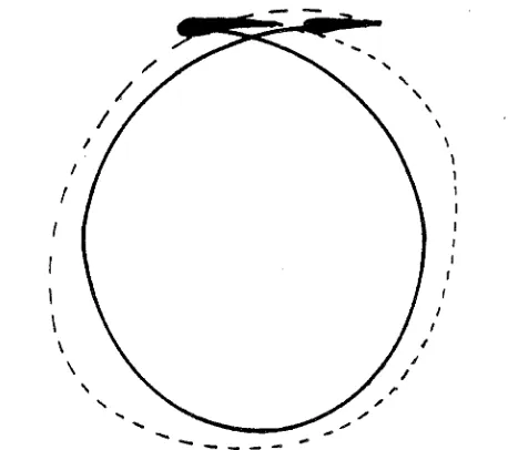
duced frequency oc/U, the theory i s inherently valid f o r other cases. Of particular interest, for instance, is the high speed propulsion mode of the Schneider propeller to which this theory can be applied with only minor changes. A uniformly valid f i r s t order solution has beenobtained in closed f o r m after making an approximation, which i s based on neglecting the variation of the curvature of the path, thus approxi- mating a prolate cycloid by a circle. Such an approximation should be physically sound since the retarded p r e s s u r e having the strongest influence upon the velocity field is that occurring in the immediate past history. F r o m the resulting value for ao(7), we find that the leading edge suction i s composed in the present c a s e of both tangential and a normal (to the blade chord) component. The n o r m a l component is linear in K ( T ) and reveals the f i r s t - o r d e r effects of the asymmetry of
5 1
cylinder in cycloidal motion tends t o support the possibility that such a component of the leading edge suction can occur. Finally, the contri- butions of the unsteady effects t o the instantaneous f o r c e and moment acting on the blade, the total power output of the turbine and the total energy lost to the fluid have been fully evaluated. It i s seen that the total power output i s equal to the r a t e of work done by the thrust plus the kinetic energy imparted to the fluid. Contrary to the quasi-steady approach, where no energy i s lost to the fluid, the unsteady approach allows a hydromechanical efficiency to be defined a s the ratio of the useful power output to the total work done by the t h r u s t (P/UTo). This allows m o r e flexibility in the design of a turbine by leaving the choice to the designer of maximizing either the hydr omechanical efficiency, thus imparting the l e a s t disturbance to the fluid, o r the mechanical efficiency (defined a s the r a t i o of the power output to the power avail- able in the s t r e a m ) , thus maximizing the total power output of the turbine. At the present time, no experimental. data a r e available r e -
garding the contribution of the curvature and of the unsteady effects on the total power output of a turbine and on the instantaneous blade
5 2 APPENDIX A
As the p r e s e n t study i s l i m i t e d to the c a s e
S2R
>>
U , R > > c ,we can define E
'
and E s u c h that, with the half chord n o r m a l i z e d t o unity,E ' = U/QR
<<
1 , E=
1 / R<<
1.We f u r t h e r m o r e a s s u m e
a ,
R, and U to b e constant. In o r d e r to c a r r y out o u r evaluation, we need t o r e c a l l the following relationships :t a n X
-
-
s i n8
-
c o s 8t
f2R/UWe can then evaluate t h e following t e r m s up to o r d e r E ( o r e I ) :
2 ) X = Arctan[ - s i n 8 a R
]
=
~ r c t a n [ - E'
s i n 8(1-
E I c o s 8)],
c o s8t-
u
3 )
-
-
1 [ - € I cosen]
=
-2
n
cos 8ht 1 t (-E s i n 8)
-
-
15 ) K ( T )
=
-
a(1-
.I c O s @ )=
-
(1-
c o s8)
,
V Q R ( 1+
c o s 8)R
=
E (1-
261 C O S6)
.
K
*
6 )
K- " - =
t-
1 2 5 1 ~ ' s i n 8 2-
V
R SlR(1 t E ' c o s 8 )=
~ E ' E (1-
E ' cos @ ) s i n 8.
(1
-
C O Se )
(1
-
2.1 c o s 6 )F o r v a l u e s of z o f o r d e r unity, i . e . , c l o s e t o t h e b l a d e , w e h a v e .
z 2 K 1
(ij)'z and ( -
=
O ( . ~ I )=
o(-~).
P K RF o r l a r g e values of z, we have 1
Z Z K 1
($
-
-
K and (-)PK
-- O ( e l )=
O(E).
.
As is r e a d i l y a p p a r e n t f r o m t h i s equation, the value of
-
zK a t any point onPK
t h e c h a r a c t e r i s t i c line i s always at l e a s t of o r d e r ( l / R ) . F u r t h e r m o r e f o r the region n e a r the blade, which c o r r e s p o n d s to l a r g e contributions to the
2 unsteady effect, i t i s of o r d e r ( 1 / ~ ).
It m a y be noted t h a t t h e c a s e
6
=
0, o r ~ K Z = 1, c o r r e s p o n d to5 4
c h a r a c t e r i s t i c lines do not go through this point, a t l e a s t up to a v e r y large r e t a r d e d time.
I£
this does happen f o r 7 '<<
7 , the effect of the r e t a r d e d5 5
A P P E N D I X B
Laplace t r a n s f o r m solution of a0(7)
We r e c a l l (1. 7 0 )
where B ( z )
=
(1+
Z )-
z
ie (1-
z 2 ),
and p ( z ) = 1 -if2
.
We can r e w r i t e this equation a swhere
and
1. Evaluation of E l ( s )
Taking a n expansion in s m a l l e of the expression in
the
b r a c k e t of (B-2), and neglecting the second and higher o r d e r t e r m s , we can e x p r e s s E 1 ( s ) a s-1
-
1-
1s z 2 z-1 lR s z z - l l B s z
56
The second integral in this expression can be integrated by part. Denoting it by E3 ( s ) , we obtain
which can be expressed a s
Replacing this expression in (B-4) leads to
Finally, using the identity (derived in Appendix C )
we obtain
E l @ ) = [Ko(s)
+
K1(s)l(l-
+ ) ?where Ko(s) and Kl ( s ) a r e the modified Bessel functions of the second kind.