BFC 5038 • •
BASIC/FOUR and
,D
are registered trademarks of BASIC/FOUR CORPORATIONCOPYRIGHT 1978 © by BASIC/FOUR CORPORATION All rights reserved.
2780/3780
SIMULATOR SYSTEM
REFERENCE MANUAL
basIc
I
Four corporation
PROPRIETARY INFORMATION
TABLE OF CONTENTS
Page
INTRODUCTION 1
SECTION 1 2780/3780 SIMULATOR . . . 3
Program Function. . . .. . . 3
Operating Characteristics. . . . ... . . . 3
VDT Format. . . . 4
Define Terminal Characteristics. . . . 6
File Queue Definition ... 6
User Data File Interface. . . . .. . . .. 11
Software Structure . . . .. 15
SECTION 2 QUEUE FILE UTILITY . . . 17
Program Function. . . . ... . . . .. 17
Operating Characteristics. . . . .. 17
SECTION 3 SIGNON FILE UTILITY . . . .. 23
Program Function. . . . .. 23
Operating Characteristics. . . . .. 23
System Impact . . . ... . . . .. 25
SECTION 4 JOB CONTROL LANGUAGE UTILITY . . . . . .. 27
Program Function. . . . .. 27
Operating Characteristics. . . . .. 27
REFERENCES. . . . . . . . . . .. 29
DATE TITLE 2780/3780 SIMULATOR SYSTEM REFERENCE MANUAL PAGE
LIST OF ILLUSTRATIONS
Figure Page
1-1 Initial Display Format. ... 3
1-2 Message Format . . . 4
1-3 Status Messages. . . . 5
1-4 Terminal Characteristics. . . . 6
1-5 File Queue Definition (Receive) . . . 6
1-6 File Queue Definition (Transmit) ... . . . 6
1-7 Operation of Receive Queue .... , . . . 7
1-8 Operation of Transmit Queue. . . . 7
1-9 Signon Definition . . . 8
1-10 Signon Definition (Double Card). . . . 8
1-11 Start Communications. . . . 8
1-12 SetDate/Time ... 11
2-1 Program Mode Selection Menu. . . . .. 17
2-2 Generate Transmit Queue. . . . .. 17
2-3 Generate Receive Queue ... 18
2-4 Add Entry To Transmit Q'ueue .. . . .. 19
2-5 Entry Number and File Name (Modify) ... : . . . .. 19
2-6 Selected Record Contents (Modify) . . . .. 20
2-7 Entry Number and File Name (Delete) . . . .. 20
2-8 Selected Record Contents (Delete) . . . .. 20
2-9 Modify Receive Queue. . . . . . . .. 21
2-10 Transmit Queue Display ... 22
2-11 Receive Queue Display . . . .. 22
3-1 Function Menu. . . . .. 23
3-2 Add To Existing File . . . .. 23
3-3 Modify Existing Entry ... , 23
3-4 Delete Existing Entry . . . .. 24
3-5 Signon Image Display .... . . .. 24
3-6 Signon I mage. . . . .. 24
DATE TITLE 2780/3780 SIMULATOR SYSTEM REFERENCE MANUAL PAGE
Table
1
2
3 4
ASCII to EBCDIC Conversion
EBCDIC to ESCII Conversion
LIST OF TABLES
Horizontal Print Control . . .
Vertical Print Control . . . . Page
12
12
13 13
DATE TITLE 2780/3780 SIMULATOR SYSTEM REFERENCE MANUAL PAGE
INTRODUCTION
Distributed Data Processing (ODP) is a multiple systems approach to information handling that offers direct cost savings through improved management control, fast data response, and a high degree of reliability. The Basic Four 2780/3780 Simulator System is a DDP system that provides an organization with the capability of handling its own internal tran-sactions independent of the host processor or other satellite systems, while still being able to share data with those systems.
This document is a reference manual for the 2780/3780 Simulator System. Program function and operating characteristics of the 2780/3780 Simulator are fully detailed in Section 1, as are various modes of operation available to support user needs. Section 2 describes the queue file utility that generates and modifies data files used by the simulator as queues
for the reception and transmission of data. Section 3 describes the SIGNON file utility which is used to specify the content and number of signon images re-quired to establish communications between a
remote terminal and a host mainframe. Section 4 defines the Job Control Language (JCL) utility which provides file management of 80-character records us-ed to transmit JCL from a Basic Four computer system to a mainframe computer.
A list of references has been included that imparts more complete information on elementary data com-munications and the IBM 2780/3780 terminals.
The Appendix describes the various steps and pro-cedures that are undertaken at a terminal to fully setup and execute the simulator program.
DATE TITLE 2780/3780 SIMULATOR SYSTEM REFERENCE MANUAL PAGE
SECTION 1
2780/3780 SIMULATOR
This section describes the function and operation of the 2780/3780 Simulator as the major software component of an integrated distributed data process-ing package. Certain details concernprocess-ing the operation of the simulator as a Remote Job Entry terminal which are functions of a particular host main frame are specific to those mainframes and, therefore, not covered in this manual.
Because of the extensive set of options offered, the user may tailor the 2780/3780 Simulator to satisfy re-quirements of his particular network.
PROGRAM FUNCTION
The 2780/3780 Simulator package allows an ap-propriate Basic Four processing system to com-municate with a host processor or other remote ter-minals that conform to the IBM 2780/3780 Data Transmission Terminal EBCDIC protocol.
As a Remote Job Entry terminal, a Basic Four system appears to the host processor as an 80-column card reader. Data transmitted from the Basic Four system are interpreted as Job Control Language (JCL), program files, and data sets. These in turn may be used to control job scheduling and ex-ecution, data set manipulation, and host system resource allocation. The host processor outputs files to the Basic Four system as though it were a 132-column printer and an 80-column card punch. Files consist of status and logging information sent at the host system's discretion and results of previously submitted jobs. Routing to printer or punch is control-led through JCL and program statements.
Communications from a Basic Four system to another 2780/3780 remote terminal consists of simple exchanges of files required since each side of the communication link is assumed to be a card reader/punch and line printer.
Various user needs are supported by several modes of operation.The standard mode supports the following basic 2780 features:
• Two records per transmission • Horizontal tabulation
• Auto turnaround
• POint-to-point network • Vertical tabulation • Auto Answer
Other operating modes can provide the following featu res:
• Single record per transmission
• 2780 multiple records per transmission block (up to 7)
• Transparency • 3780 protocol
• 3780 transparency with extended buffer
The simulation is controlled by menu-driven in-quiry/responses. These sequences provide the operator vvith commands necessary to select protocol and options, define file queues, and to start or stop the data transfer.
Data transfer is controlled by file queues which are built by a supplied utility. These queues (one for transmit and one for receive) specify by file name and device type where the data are to be transferred to/from. This allows the user to spool received data to multiple physical files and to concatenate multiple data sets for transmission.
OPERATING CHARACTERISTICS
The following paragraphs describe the operation of the program and the interaction between the system and the opeator.
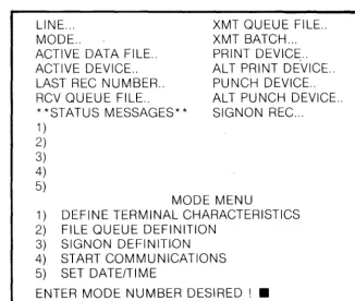
The simulator is activated by the operator using the key-in RU N "*CP". The system then loads the simulator from the disc and initiates its execution. The simulator clears the VDT and initializes the display format as shown in Figure 1-1.
LINE ... MODE ..
ACTIVE DATA FILE .. ACTIVE DEVICE .. LAST REC NUMBER .. RCV QUEUE FILE ..
**STATUS MESSAGES** 1 )
2) 3) 4) 5)
XMT QUEUE FILE .. XMT BATCH ... PRINT DEVICE .. ALT PRINT DE·VICE .. PUNCH DEVICE .. ALT PUNCH DEVICE .. SIGNON REC ...
MODE MENU
1) DEFINE TERMINAL CHARACTERISTICS 2) FILE QUEUE DEFINITION
3) SIGNON DEFINITION 4) START COMMUNICATIONS 5) SET DATE/TIME
ENTER MODE NUMBER DESIRED! •
Figure 1-1. Initial Display Format
DATE TITLE 2780/3780 SIMULATOR SYSTEM REFERENCE MANUAL PAGE
[image:11.824.449.776.640.916.2]VOT FORMAT
The VDT format consists of a single, fixed template maintained through all phases of simulator operation and a number of variable fields controlled by the operator-simulator dialogue and real-time com-munications events. Th"is format is divided into three functional areas.
1. Simulator Real-Time Operational Status
The first area of the VDT display is the real-time operational status of the simulator shown in the fields described below:
LINE-The current status of the communications link (OPEN/CLOSED). The line OPEN condition is maintained for as long as the modems at both ends of the communications link are off-hook and in "data" mode.
MODE-Direction of communications with respect to the simulator (I NACTIVEITRANSM IT/RECEIVE).
ACTIVE DATA FILE-Name of the file which is cur-rently being transmitted from, or received int%r "NONE" during INACTIVE mode. Names come from the transmit or receive file queues and conform to BASIC file or device name requirements.
ACTIVE DEVICE-Device corresponding to ACTIVE DATA FILE (NONE/DISC/PRINTER 1/CON-SOLE/PRINTER 2/MAG TAPE).
LAST REC NUMBER-A count of the number of records transmitted or received in a logical file (0000-9999). The count will not reset between chained files.
RCV QUEUE FILE-File name of operator/selected receive queue.
XMT QUEUE FILE-File name of operator selected transmit queue.
XMT BATCH-A count of the files transmitted dur-ing a communications session (000-999). If several files are chained, the count will increment only after the last file in the chain is transmitted.
The following four fields are all filled from informa-tion contained in the operator-selected receive queue.
Possible values are (NONE/DISC/PRINTER1/CON-SOLE/PRINTER 2/MAG TAPE).
PRINT DEVICE-Device to receive files which con-tain 2780/3780 printer routing or those which concon-tain no routing information.
ALT PRINT DEVICE-Alternate device which is automatically selected by the simulator if an error or end of file condition occurs on device receiving printer-routed information.
PU NCH DEVICE-Device to receive files which contain 2780/3780 punch routing.
AL T PU NCH DEVICE-Alternate device which is automatically selected by the simulator if an error or end of file condition occurs on device receiving punchrouted information.
-2. Status Messages
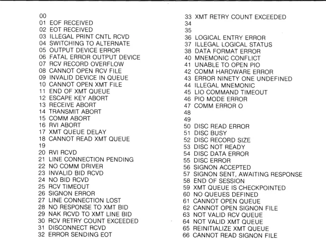
The second area of the VDT display, entitled **STATUS MESSAGES**, is a list of messages pro-viding a limited historical log of exceptional conditions (see Figure 1-2). The format for a message is:
HM:MM:SS(NN) ... message ...
LINE... XMT QUEUE FILE ..
MODE.. XMT BATCH ...
ACTIVE DATA FILE.. PRINT DEVICE .. ACTIVE DEVICE.. ALT PRINT DEVICE .. LAST REC NUMBER.. PUNCH DEVICE .. RCV QUEUE FILE.. ALT PUNCH DEVICE .. **STATUS MESSAGES** SIGNON REC ...
1) 09:35:26(01) NOT VALID RCV QUEUE 2) 09:36:20(01) REWIND XMT QUEUE
3) 09:38:05(63) LINE CONNECTION PENDING 4)
5)
Where HH:MM:SS is the system time in hours, minutes, and seconds respectively. NN is a count (01-99) of successive times a message has occurred. This prevents recurrent messages from dominating the message list. Five messages may be displayed simultaneously. Additional messages will then overlay the oldest message screened. Figure 1-3 is a listing of all status messages.
00
01 EOF RECEIVED 02 EOT RECEIVED
03 ILLEGAL PR I NT CNTL RCVD 04 SWITCHING TO ALTERNATE 05 OUTPUT DEVICE ERROR
06 FATAL ERROR OUTPUT DEVICE 07 RCV RECORD OVERFLOW 08 CANNOT OPEN RCV FILE 09 INVALID DEVICE IN QUEUE 10 CANNOT OPEN XMT FILE 11 END OF XMT QUEUE 12 ESCAPE KEY ABORT 13 RECEIVE ABORT 14 TRANSMIT ABORT 15 COMM ABORT 16 RVI ABORT
17 XMT QUEUE DELAY
18 CANNOT READ XMT QUEUE 19
20 RVI RCVD
21 LINE CONNECTION PENDING 22 NO COMM DRIVER
23 INVALID BID RCVD 24 NO BID RCVD 25 RCV TI M EOUT 26 SIGNON ERROR
27 LINE CONNECTION LOST 28 NO RESPONSE TO XMT BID 29 NAK RCVD TO XMT LINE BID 30 RCV RETRY COUNT EXCEEDED 31 DISCONNECT RCVD
32 ERROR SENDING EOT
33 XMT RETRY COUNT EXCEEDED 34
35
36 LOGICAL ENTRY ERROR 37 ILLEGAL LOGICAL STATUS 38 DATA FORMAT ERROR 40 MNEMONIC CONFLICT 41 UNABLE TO OPEN PIO 42 COMM HARDWARE ERROR
43 ERROR NINETY ONE UNDEFINED 44 ILLEGAL MNEMONIC
45 L10 COMMAND TIMEOUT 46 PIO MODE ERROR
47 COMM ERROR 0 48
49
50 DISC READ ERROR 51 DISC BUSY
52 DISC RECORD SIZE 53 DISC NOT READY 54 DISC DATA ERROR 55 DISC ERROR
56 SIGNON ACCEPTED
57 SIGNON SENT, AWAITING RESPONSE 58 EN 0 OF SESSION
59 XMT QUEUE IS CHECKPOINTED 60 NO QUEUES DEFINED
61 CANNOT OPEN QUEUE
[image:13.826.118.766.210.689.2]62 CANNOT OPEN SIGNON FILE 63 NOT VALID RCV QUEUE 64 NOT VALID XMT QUEUE 65 REINITIALIZE XMT QUEUE 66 CANNOT READ SIGNON FILE
Figure 1-3. Status Messages
DATE TITLE 2780/3780 SIMULATOR SYSTEM REFERENCE MANUAL
8/1/78 SECTION 1 2780/3780 SIMULATOR
3. Simulator Menus
The third area of display consists of various menus and a prompt line. All operator/simulator dialogue is confined to this area. The primary mode selection menu is shown in Figure 1-1. Secondary menus are
listed in Figure 1-4 and described in the following
paragraphs.
LINE ... MODE ..
ACTIVE DATA FILE .. ACTIVE DEVICE .. LAST REC NUMBER .. RCV QUEUE FILE ..
**STATUS MESSAGES** 1 )
2) 3) 4) 5)
XMT QUEUE FILE .. XMT BATCH ... PRINT DEVICE .. ALT PRINT DEVICE .. PU NCH DEVICE .. ALT PUNCH DEVICE .. SIGN ON REC ...
*DEFINE TERMINAL CHARACTERISTICS 1) 2780 STANDARD
2) 2780 WITH MULTIRECORD FEATURE 3) 2780 SINGLE RECORD
4) 3780 STANDARD
5) 3780 EXPANDED TRANSPARENCY ENTER MODE NUMBER DESIRED! •
Figure 1-4. Terminal Characteristics
DEFINE TERMINAL CHARACTERISTICS (Figure 1-4)
This mode allows the operator to direct the simulator to use either the 2780 or 3780 protocol and to select various options within these protocols. The simulator options correspond to certain throughput enhancement features available on hard-wired 2780/ 3780 terminals. It is desireable to select the most effi-cient option available without exceeding the capabilities existing at the contacted remote terminal or mainframe. Once a mode has been selected by entering the corresponding number 1-5, program con-trol returns to the primary mode selection menu.
2780 STANDARD-This mode will describe to the simulator that only two records per transmission block are to be sent to the remote terminal or host. This is the default mode if no other is chosen.
2780 WITH MULTIRECORD FEATURE-This mode will specify that up to seven records per transmission block are itO be sent to the remote terminal o'r host. This is accomplished by deleting trailing blanks fat each record before building a transmission block. This is the most efficient mode for 2780 transmission. If transparent data are being sent, trailing blank deletion will not occur, and this mode becomes equivalent to 2780 STANDARD.
2780 SINGLE RECORD-This mode will specify that only one record per transmission block is to be sent to the remote terminal or host. Single record is the least efficient 2780 mode and should only be used for transmission to non-standard terminals with single
record buffers.
3780 STANDARD-This mode will specify that the logical and line level programs are to function in the 3780 protocol. The protocol will be IBM-compatible for a point-to-point network toporogy. 3780 Standard mode may be used to transmit either text or transparent data. Transparent data transmission in this mode is less efficient than 3780 EXPANDED TRANSPARENCY since the data are sent one record per communications block.
3780 EXPANDED TRANSPARENCY-This mode will enable the 3780 expanded transparency block feature as defined in IBM's component information for the 3780. This mode specifies that six 80-character records will be transmitted in transparent format without record separators. This mode should not be used for text data. This is the recommended mode for Basic/Four to Basic/Four data file transmission.
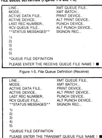
FILE QUEUE DEFINITION (Figures 1-5 and 1-6)
LINE ... MODE ..
ACTIVE DATA FILE .. ACTIVE DEVICE .. LAST REC NUMBER .. RCV QUEUE FILE ..
**STATUS MESSAGES** 1 )
2) 3) 4) 5)
*QUEUE FILE DEFINITION
XMT QUEUE FILE .. XMT BATCH ... PRI NT DEVICE .. ALT PRINT DEVICE ..
PUNCH DEVICE .. ALT PUNCH DEVICE .. SIGNON REC ...
PLEASE ENTER THE RECEIVE QUEUE FILE NAME! • Figure 1-5. File Queue Definition (Receive)
LINE ... MODE ..
ACTIVE DATA FILE .. ACTIVE DEVICE ..
LAST REC NUMBER .. RCV QUEUE FILE ..
**STATUS MESSAGES** 1)
2) 3) 4) 5)
*QUEUE FILE DEFINITION
XMT QUEUE FILE .. XMT BATCH ... PRINT DEVICE .. AL T PRI NT DEVICE .. PUNCH DEVICE .. ALT PUNCH DEVICE .. SIGNON REC ...
[image:14.822.39.349.218.527.2] [image:14.822.382.726.460.926.2]File queues define where data for transmission are found or where data are stored/displayed on recep-tion.
The simulator will first prompt the operator for the file name of the receive file queue:
PLEASE ENTER THE RECEIVE QUEUE FILE NAME!
The operator should enter the name of a receive file queue previously generated by ",QF". Acceptable file names consist of one to six characters. The file is opened and read. If it is a valid receive file queue, the PRINT DEVICE, ALT PRINT DEVICE, PUNCH DEVICE, ALT PUNCH DEVICE, and RCV QUEUE FILE fields on the VDT are updated and control proceeds to the next prompt. If the file is not available or is not a valid receive queue, the operator is reprompted for the receive file queue name and a status message is displayed (CAN NOT OPEN QU EU E or NOT VAll 0 RCV QUEUE). The prompt may be bypassed by enter-ing a carriage return with no file name (Figure 1-7). This simulator will then prompt for the transmit file
queue:
PLEASE ENTER THE TRANSMIT QUEUE FILE NAME! The operator should enter the name of a transmit file queue previously generated by ",QF". As above, one to six characters are accepted, and a single car-riage return will bypass the prompt. The indicated file is opened, locked, and the first two records are read to verify a valid transmit file queue format. If all is cor-rect the XMT QUEUE FILE field of the VDT is updated and the program returns to the primary mode menu. Otherwise, the operator is reprompted for the transmit file queue name, and a status message is displayed (CANNOT OPEN QUEUE or NOT VALID XMT QUEUE). If the transmit file queue has been checkpointed this will be indicated by a status message (XMT QUEUE IS CHECKPOINTED), since transmission will begin from the checkpoint (see START COMMUNICATIONS sec-tion). If the transmit file queue has already been transmitted to completion, the operator is warned (REINITIALIZE XMT QUEUE) and reprompted for the transmit file queue name (Figure 1-8).
LINE PRINTER --- ... _ _ _ _ _ _ _ _ _ ...
DISC FILE A ---- PRIMARY PRINT DEVICE
---~~---~~~~ ALTERNATE PRINT DEVICE
DISC FILE B _---:_-:. PRIMARY PUNCH DEVICE
DISC FILE C _--- ALTERNATE PUNCH DEVICE
RECEIVE QUEUE
12780/3780
I
SIMULATOR
TO REMOTE CPU
The receive queue established by ",OF", pOints to devices or files to which data from the remote CPU may be directed. Two different data streams may be received from the remote CPU: (1) print images (records up to 134 characters), and (2) punch images (records up to 80 characters). If the primary device to which the stream is directed becomes in-operative (printer jam, disc file full, etc.) output will automatically be directed to the alternate device.
Figure 1-7. Operation of Receive Oueue
FI LE/DEVICE NO.1
....
FILE/DEVICE NO.2 ... _ _ _ _ _ ... ... FI LE/DEVICE NO.1
... FILE/DEVICE NO. 2
t--_~12780/3780
II-:---~.
FILE/DEVICE NO. N _---- ... FILE/DEVICE NO. N . SIMULATOR _
TRANSMIT QUEUE
TO REMOTE CPU
The simulator transmits data from specified files or devices to the remote CPU. Sequencing of the transmission is con-trolled by the transmit queue which is a file containing information concerning input streams which form the transmission to the remote CPU. Creation of the transmit queue is via the program" ,OF".
Figu re 1-8. Operation of Transmit Oueue
DATE TITLE 2780/3780 SIMULATOR SYSTEM REFERENCE MANUAL PAGE
The file queue selection made may be entered any number of times to reselect either the transmit or receive file queues. Bypassing either prompt with a carriage return will leave a previously selected queue unchanged.
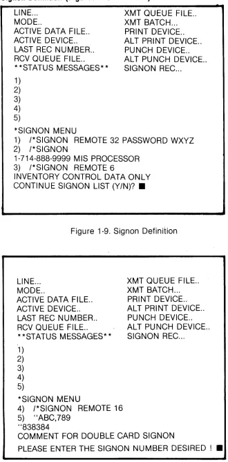
Signon Definition (Figures 1-9 and 1-10)
LINE ... MODE ..
ACTIVE DATA FI LE .. ACTIVE DEVICE .. LAST REC NUMBER .. RCV QUEUE FILE ..
**STATUS MESSAGES**
1 ) 2) 3) 4) 5)
*SIGNON MENU
XMT QUEUE FILE .. XMT BATCH ... PRINT DEVICE .. ALT PRINT DEVICE .. PUNCH DEVICE .. AL T PU NCH DEVICE .. SIGNON REC ...
1) /*SIGNON REMOTE 32 PASSWORD WXYZ 2) /*SIGNON
1-714-888-9999 MIS PROCESSOR 3) j*SIGNON REMOTE 6
INVENTORY CONTROL DATA ONLY CONTINUE SIGNON LIST (Y/N)? •
Figure 1-9. Sign on Definition
LINE ... MODE ..
ACTIVE DATA FI LE .. ACTIVE DEVICE .. LAST REC NUMBER .. RCV QUEUE FILE ..
**STATUS MESSAGES**
1 )
2)
3) 4) 5)
*SIGNON MENU
4) /*SIGNON REMOTE 16 5) "ABC,789
"838384
XMT QUEUE FILE .. XMT BATCH ... PRINT DEVICE .. ALT PRINT DEVICE .. PU NCH DEVICE .. ALT PUNCH DEVICE .. SIGNON REC ...
COMMENT FOR DOUBLE CARD SIGNON
PLEASE ENTER THE SIGNON NUMBER DESIRED! •
Figure 1-10. Signon Definition (Double Card)
Remotes communicating with host processors often need to identify themselves after the physical communications link has been established. This is normally done by transmitting a SIGNON card image
to the host. The format and content of the image may vary from host to host, and a particular Basic Four system may communicate to more than one host. Therefore, A SIGNON file has been established and a utility program (" ,LOGON") provided to build the file.
This mode selection first allows the operator to review the entire SIGNON file. The file is displayed se-quentially three records at a time (two records
at
a time if double card signons are included). After each group is displayed, the operator is prompted:CONTINUE SIGNON LIST (YIN)?
Each time the operator responds "Y", the simulator will continue to cycle through the records of the SIGNON file. If the operator responds "N", the program will next prompt for one of the signon images to be chosen by number:
PLEASE ENTER THE SIGNON NUMBER DESIRED!
The first 27 characters of the selected signon will be displayed in the SIGNON REC field of the VDT, and the program will return to the primary mode menu.
The signon selection made may be entered any number of times to reselect the signon. A carriage return in response to the signon number prompt will cause the program to return to the primary mode menu without affecting a previously selected signon. If a signon number greater than any record existing in the SIGNON file is entered, any previously selected signon is "deselected," the SIGNON REC field of the VDT is blanked, and control returns to the primary mode menu.
If for any reason the SIGNON file cannot be ac-cessed, an appropriate status message is displayed (CANNOT OPEN SIGNON FILE or CANNOT READ SIGNON FI LE).
Start Communications (Figure 1-11)
LINE ... MODE ..
ACTIVE DATA FILE .. ACTIVE DEVICE .. LAST REC NUMBER.. RCV QUEUE FILE ..
**STATUS MESSAGES**
1) 2) 3) 4) 5) *START COMMUNICATIONS
XMT QUEUE FILE .. XMT BATCH ... PRINT DEVICE .. ALT PRINT DEVICE .. PUNCH DEVICE .. ALT PUNCH DEVICE .. SIGNON REC ...
PRIMARY/SECONDARY TRANSMITTER (P/S)? •
[image:16.816.35.365.172.841.2] [image:16.816.393.711.696.919.2]Once appropriate terminal characteristics, file queues, and signon information have been defined, the operator may start communications. Sessions with a host processor or with another 2780/3780 ter-minal differ partially in setup requirements and se-quence of events to establish and maintain the com-munications link.
The normal setup for communicating with another 2780/3780 terminal would be to have transmit and receive file queues defined, but no signon defined. Because a signon has not been defined, the simulator will prompt:
PRIMARY/SECONDARY TRANSMITTER (P/S)?
If the operator enters "P", the simulator will pro-ceed to establish the communications link, then enter transmit mode. If the operator enters "S', the simulator will proceed to establish the communica-tions link, then enter receive mode. By prior agree-ment, one 2780/3780 terminal should transmit first while the other receives first (Le., in a Basic Four to
Basic Fou r situation, one operator selects" P" while the other selects "S"). If this procedure is not follow-ed, the problem of "contention" arises. Both devices attempt to transmit or receive simultaneously: Com-munications mayor may not be established under these circumstances. Simply entering a carriage return to the primary/secondary prompt will cause the program to return to the primary mode ,menu without starting communications.
Communications with most mainframe processors require that a signon and a receive file queue have been selected. A transmit file queue will normally also be used, but is optional. Because a sigr:lOn has been selected, the simulator must by definition be the first side of the communications link to transmit. Thus, the contention problem discussed above is avoided and the program will establish a communications link without displaying the primary/secondary transmitter prompt.
The program will now attempt to establish the com-munications link. If the system is in a switched or dial-up network, the program will wait for the physical communication link to be established. For a terminal operating in the unattended mode(Auto Answer), the host processor or other 2780/3780 terminal must call to establish the physical link. For a terminal operating in the attended mode, the operator must establish the physical link by dialing the host or other 2780/3780 terminal and making the data set (modem) ready. Un-til the link is established, the simulator will display the message (LINE CONNECTION PENDING).
If the system is operating on a leased/dedicated network, the physical link is already established, and
communications can begin immediately. In either case, the LINE field of the VDT is now set to OPEN to flag the link as established.
If no signon is selected, the simulator will enter the transmit or receive mode as dictated by the response to the primary/secondary transmitter prompt. Other-wise, the simulator will transmit the selected signon card image(s) as a file, then enter the receive mode to await response f.rom the host processor. This is denoted by a status message (SIGNON SENT, AWAITING RESPONSE). Typical response would be for the host to send log-on information and/or results of previously submitted jobs. If the signon cannot be transmitted, a status message is displayed (SIGNON ERROR) and program control returns to the primary mode menu. If the signon is sent, but the information contained is not acceptable, the host poscessor will terminate communications.
Once communications has been established, the simulator will alternate between transmit and receive modes untn transmit and receive file queues have been exhausted, an unrecoverable error occurs, or the operator manually aborts communications.
Through each cycle in transmit mode, the simulator will transmit one logical file, if available, then relin-quish control to the host processor or other remote terminal by sending a 2780/3780 End of Trnasmission indicator. Access to the data comprising a logical file is controlled by information stored in the transmit file queue: file (or device) names, transmission status, checkpoints, file chains, and data type.
Checkpoints allow the operator to automatically resume an earlier interrupted transmission from the point of interruption. A record checkpoint exists for each file listed in the transmit file queue, and a master file checkpoint exists to mark progress through the transmit queue. When a transmit queue is built, the queue file utility initializes each file checkpoint to the first record of the file and the master file checkpoint to the first file in the queue. The simulator finds the file (or device) name currently indicated by the file check-point, opens it (disc files are locked), reads it, and transmits it. The record checkpoint is advanced for each record read. After the file has been transmitted, the file is closed and the file checkpoint is advanced, then both checkpoints are written into the transmit file queue.
Current check points values (corrected for the number of records read, but not yet received at the other side of the communications link) are written into the transmit file queue should an abort occur. A transmit file queue, which has been transmitted to completion, must be "re-wound" before it may be used again for transmission. The queue file utility may be used to reinitialize the record checkpoints and master file checkpoint.
DATE TITLE 2780/3780 SIMULATOR SYSTEM REFERENCE MANUAL PAGE
A file history indicator is written into the transmit file queue along with the checkpoints, i.e., "COMPLETED" or "BREAKPOINTED." A history of "BREAKPOINTED". is further marked to differentiate operator intervention versus other errors, i.e., "ESCAPE KEY ABORTED" or "INTERRUPTED."
Each file in the transmit file queue has a transmit status indicator, "READY," "SKIP," or "WAIT." Files marked "READY" are accessed for transmission as previously indicated. Files marked "SKIP" are not transmitted. Instead, the master file checkpoint is ad-vanced to the next file in the queue until a "READY" or "WAIT" file is found. When a file marked "WAIT" is encountered, a status message (XMT QUEUE DELAY) and a prompt are screened:
HOLD/SEN D FI LE "xxxxxx" (HIS)?
Where xxxxxx is the file (or device) name. If'the operator selects "S", the file is sent exactly like a "READY" file. If the operator selects "H", the simulator relinquishes transmit mode by sending a
2780/3780 end of transmission indicator without
hav-ing sent any data. The checkpoints are not advanced and program control proceeds to the receive mode. The same "WAIT" file will be encountered on every subsequent retu rn to transmit mode until the operator selects
"s"
(send).Skip files allow the operator to select which of several optional files listed in the queue to transmit, e.g., alternate JCL files specifying output to printer or to punch. Wait files allow the operator to del~y pro-gress through the transmit queue. For instance, one job may not run correctly until a previously submitted job completes. Wait files should not be used in transmit file queues intended for unattended opera-tion.
If the current file in the transmit file queue is chained, the simulator will not revert to receive mode after that file has been transmitted. Rather, the next file in the queue is accessed and transmitted.This continues until an unchained file is found, terminating the chain. A 2780/3780 end of file indicator will be sent only after the last file in the chain. This causes the host processor or other remote terminal to
con-catenate a series' of separate physical files into one logical file. Chaining is convenient for combining files of standardized information with frequently updated information, e.g., adding JCL to program or data files.
Host processors normally support checkpointing only on a complete file basis rather than on a record basis. When communications is started, if a signon was selected (communicating with a host processor), the simulator will rewind the record checkpoint to the start of a checkpointed file. If the checkpoint lies
within a series of chained files, the checkpoint is backed up to the beginning of the chain (start of the logical file). If a signon was not selected, the simulator will start transmitting the file from the record in-dicated in the record checkpoint. Record checkpoint-ing, is of course, only meaningful when applied to ran-dom access devices.
After the last entry in the transmit file queue has been transmitted, the transmit file queue is closed and transmit logic is disabled. This is denoted by status messages (END OF XMT QUEUE and TRANSMIT ABORT). Program control passes to receive mode and remains there as long as receive is enabled.
Through every cycle in receive mode, the simulator pauses nominally to allow the host processor or other remote terminal to initiate a transmission. If the host or other remote does not initiate a transmission within that frame time, the simulator reverts to transmit mode. In receive mode, the simulator will accept any number of contiguous files, demarked by 2780/3780
end of file indicators, up to the capacity of the selected receive devices (files). Upon receipt of a
2780/3780 end of transmission indicator, the
simulator will automatically revert to transmit mode. Receipt of end of file or end of transmission indicators is denoted by status messages (EOF RCVD or EOT RCVD).
Two receive devices (files) will be opened the first time the simulator enters receive mode and will re-main open for the duration of the communications session. These devices (files) are the ones which were specified by· the selected receive file queue as PRINT DEVICE and PUNCH DEVICE. Received files will be routed to these (files) according to 2780/3780
routing indicator embedded within the data. Files which contain no routing indicators will default to the PRINT DEVICE. Should an error, including end of file condition, occur on a receive device (file), the simulator will close that device and open the ALT PRINT DEVICE or ALT PUNCH DEVICE, as ap-propriate, and continue to receive.
Some modems may not terminate the physical communications link after the simulator has closed the line. I n this case, the operator must" hang-up" the phone to prevent a large phone bill.
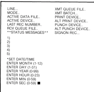
SET DATE/TIME (Figure 1-12)
LINE ... MODE ..
ACTIVE DATA FILE .. ACTIVE DEVICE .. LAST REC NUMBER .. RCV QUEUE FILE ..
**STATUS MESSAGES** 1 )
2) 3) 4) 5)
*SET DATEITIME ENTER MONTH (1-12) ENTER DAY (1-31) ENTER YEAR (0-99) ENTER HOU R (0-23) ENTER MIN (0-59) ENTER SEC (0-59) •
XMT QUEUE FILE .. XMT BATCH ... PRINT DEVICE .. ALT PRINT DEVICE .. PUNCH DEVICE .. ALT PUNCH DEVICE .. SIGNON REC ...
Figure 1-12. Set Date/Time
This mode selection allows the operator to set the system date (MONTH, DAY, YEAR) and the system time (HOUR, MONTH, SECOND) for logging purposes.
USER DATA FILE INTERFACE
Successful and efficient operation of the 2780/3780 simulator depends greatly upon proper definition of user data files and appropriate description of these files in the transmit and receive file queues.
Systems that receive data from
a
2780 expect 80-byte card image records. To comply with this re-quirement, the simulator will deblock data file recordsread into 80-byte card image records before transmis-sion. Deblocking has no apparent effect on files whose records are 80 bytes long. Files with records longer or shorter than 80 bytes will appear "skewed" after transmission. Deblocking of files whose total size (record length x number of records) is not an in-tegral multiple of 80, produces a short record when the last card image is formed. This residual record is padded to a full 80 bytes using blanks in text mode or nulls in transparent mode.
Host processors frequently attach positional significance to data in JCL or program files relative to an 80-byte card image. The contents of "pure" data files are irrelevant to the host processor. Skewed records would not prevent successful transmission; however, the data would need to be restored to its original format for later use at the host processor.
Thus "pure" data files for transmission to a host processor may be created to contain other than 80 bytes of data. An application program on the host porcessor could be used to reformat the data, if it were skewed in transmission.
Data used by a 2780/3780 is classified as text (character) data or transparent (binary) data. Each file in the transmit file queue is marked for the simulator as text or transparent. The content of data received by the simulator determines whether it is text or transparent.
Systems receiving data from a 2780/3780 expect text data to be in the EBCDIC character set. All files which are marked in the transmit file queue as text will be translated from ASCII to EBCDIC prior to transmission. (see Table 1).
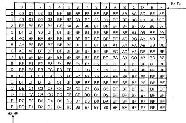
Conversely, all text data received by the simulator will be translated from EBCDIC to ASCII (see Table 2).
Transparent data may assume any values and so are not restricted to any particular character set. All files which are marked transparent in the transmit file queue will be sent as read, without translation. Transparent data received will not be translated.
Chained files in the transmit file queue represent a single logical file. Thus all files in a chain must be marked uniformly either as text data or as transparent data. If transparent data must be chained to JCL and/or program files for communications with a host processor, the JCL and/or program files should be created as EBCDIC data and marked transparent in the transmit file queue.
Non-Standard Record Length
. The simulator can reformat data received in transparent mode. Records will be reblocked from the 80-byte card images received to the record size specified by the receive file queue. Thus, records longer or shorter than 80 bytes may be transmitted Basic/Four to Basic/Four without any apparent skew-ing.
To transfer long or short records successfully, the transmitting side ot the link must mark the file transparent in its transmit file queue. The receiving side of the link must have the record size field of the selected receive file queue set equal to the actual record size of the file to be transferred.
Routing and Print Control
A 2780/3780 terminal is required to perform receive device routing and printer carriage control based on special character sequences embedded within received data. These characters are stripped from the data when the function is performed. Files received from a host processor will contain routing and/or print
DATE TITLE 2780/3780 SIMULATOR SYSTEM REFERENCE MANUAL PAGE
[image:19.824.104.424.161.476.2]Table 1 ASCII to EBCDIC Conversion
~
0000 0001 0010 0011 0100 0101 0110 0111 1000 1001 1010 1011 1100 1101 1110 1111 B8.B5 0 1 2 3 4 5 6 7 8 9 A B C D E F1000 8 NULL SOH STX ETX EDT ENQ ACK BEL BS HT LF VT FF CR SO SI 00 01 02 03 37 2D 2E 2F 16 05 25 OB OC OD OE OF 1001 9 DLE DC1 DC2 DC3 DC4 NAK SYN ETB CAN EM SUB ESC FS GS RS US 10 11 12 13 3C 3D 32 26 18 19 3F 27 1C 1D 1E 1F 1010 A SPACE !
"
# $ % &,
( )*
+,
- • I40 5A 7F 7B 5B 6C 50 7D 4D 5D 5C 4E 6B 60 4B 61 1011 B 0 1 2 3 4 5 6 7 8 9 • •
.
,
<=
> ? FO F1 F2 F3 F4 F5 F6 F7 F8 F9 7A 5E 4C 7E 6E 6F 1100 C @ A B C D E F G H 1 J K L M N 07C C1 C2 C3 C4 C5 C6 C7 C8 C9 D1 D2 D3 D4 D5 D6 1101 D P Q R S T U V W
x
Y Z ["-
[t
-D7 D8 D9 E2 E3 E4 E5 E6 E7 E8 E9 CO EO DO 5F 6D 1110 E
,
a b c d e f 9 h i j k I m n 079 81 82 83 84 85 86 87 88 89 91 92 93 94 95 96 1111 F P q r s t u v w x y z {
I
} f'V DEL97 98 99 A2 A3 A4 A5 A6 A7 A8 A9 CO 6A DO A1 07
Table 2 EBCDIC to ASCII Conversion
B4-B1
0
1
2
3
4
5
6
7
8
9
A
B
C D
E
F
0
80
81
82
83 BF 89 BF FF BF BF SF 8B 8C 80 8E 8F
1
90
91
92
93
BF BF
88BF
98 99 BEBF
9C 90 9E9F
2
BF BF BF BF BF 8A 97 9B BF BF BF BF BF 85 86 87
a
BF BF
llli
BF BF BF BF
84BF BF BF RF q4 qf)
RF ClA
4 AO BF BF BF BF BF BF BF BF BF BF AE Be A8 AB FC
5
A6
BF BF BF BF BF BF BF BF BF A1
A4
AA
A9 BB DE
6 AD AF BF BF BF BF BF BF BF BF FC AC A5 OF BE BF
7
BF BF BF BF BF BF BF BF BF EO BA A3 CO A7 BO A2
8
BF E1
E2
E3
E4
E5 E6 E7 E8 E9 BF BF BF BF BF BF
9
RF
EAFR Fr. Fn FF
1=1= EOF1
F?RF
RI= RI= RI= RI= RI= ARE
IT £aF4
Ff)
FR F7
FR
Fq FA RF RF RF RF RF RF
[image:20.822.39.717.115.479.2] [image:20.822.84.717.567.988.2]control based on JCL and programs executed at the host processor. A 2780/3780 terminal may transmit files containing routing and/or print control to another 2780/3780 but never to a host processor.
Files to be transmitted by the simulator may include routing and print control sequences. These special character sequences cannot usually be keyed directly into the data but must instead be created by a BASIC program.
A punch routing sequence may appear only in the first character position(s), left most characters, of the first record of a logical file. (First file only of a chain in the transmit file queue). 2780 punch routing is "ESC" "4", 1 BB4 hex in ASCII or 27F4 hex in EBCDIC. Do not use the hex value 9B for an ASCII ESC. 3780 punch routing is "DC1", 91 hex in ASCII or II hex in EBCDIC.
Printer control may include both horizontal anq ver-tical carriage control functions. Horizontal print con-trol provides for spacing between fields on a print line. A special non-data horizontal print control record is sent to define tab stops. On encountering an "HT" character in succeeding data records, the simulator will insert blanks into the record from the position of the HT until the relative position of the next tab stop in the horizontal print control record. The result is similar to depressing a tabulator key on a typewriter, causing the carriagE? to space over to the next tab stop.
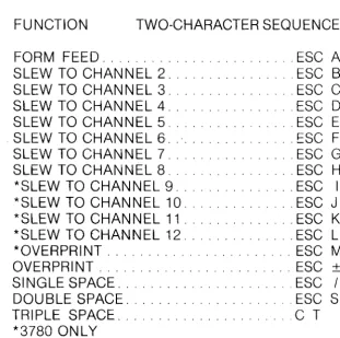
Table 4 Vertical Print Control
FUNCTION TWO-CHARACTER SEQU ENCE
FORM FEED ... ESC A SLEW TO CHAN N EL 2. . . . .. . ESC B SLEW TO CHAN N EL 3 ... ESC C SLEW TO CHANNEL 4 ... ESC D SLEW TO CHANNEL 5 ... ESC E SLEW TO CHANNEL 6 ... ESC F SLEW TO CHANNEL 7 ... ESC G SLEW TO CHANNEL 8 ... ESC H *SLEW TO CHANNEL 9 ... ESC I *SLEW TO CHANNEL 10 ... ESC J *SLEW TO CHANNEL 11 ... ESC K *SLEW TO CHANNEL 12 ... ESC L *OVERPRINT ... ESC M
OVERPRINT ... ESC ±
SI NGLE SPACE ... ESC / DOU BLE SPACE ... ESC S TRIPLE SPACE ... C T
*3780 ONLY
NOTE:When ESC is coded in Business BASIC 8-Bit ASCII, use 1 B hex. E.G. 20 LET A$ = $1 Bc1$
+
A$ would add ESC A to the character string A$.Table 3 Horizontal Print Control
Horizontal Print Control Record
~§gJil
________ ._. _________ .
Column 1 position Column 78 position
~I~~~~~~~~~~~~~~~~
80 Characters Total~~~~~~~~~~~~~~~.
I
I ..
Two-character Escape Sequence
Tap Stop Field. HT character marks column position of a tab stop. Blank characters mark non-tab stop column positions
~I
A 2780/3780 may send 80-byte horizontal print control records to another 2780/3780 but may receive 132 byte print control records from a host processor.
Example of horizontal print control record to set tab stops in columns 10, 20, 30, 40, 50, 60, 70. Example is shown in ASCII characters expressed as hexadecimal:
1 B 89 AO AO AO AO AO AO AO AO AO 89 AO AO AO AO AO AO AO AO AO 89 AO AO AO AO AO AO AO AO AO 89 AO AO AO AO AO AO AO AO AO 89 AO AO AO AO AO AO AO AO AO 89 AO AO AO AO AO AO AO AO AO 89 AO AO AO AO AO AO AO AO AO
Example of data record to be used with above. (HT) represents a horizontal tab character.
THIS PRINTS STARTING IN COLUMN 1 (HT) THIS PRINTS STARTING IN COLUMN 40
DATE TITLE 2780/3780 SIMULATOR SYSTEM REFERENCE MANUAL PAGE
[image:21.822.467.779.121.431.2]Any number of print control records may be sent within
a'
file to redefine the tab stops. If a transmission is restarted from a checkpoint, the operator must en-sure that the record checkpoint is backed up to in-clude the last horizontal tab control record, otherwise the results would be unpredictable.Vertical print control provides for spacing between print lines. These control characters may appear on any record in a file but must always be the leftmost characters. 2780/3780 print control characters are converted to BASIC compatible print control mnemonics. The record is always printed before the print control function is performed.
Use of these facilities increases transmission speed by eliminating the need to transmit fields of blanks or blank lines to effect output formatting. See
Tables 3 and 4 for details of horizontal and vertical print control.
Transmission Devices
A 2780/3780 is basically a unit record device with fixed record lengths and sequentially accessed files. Although the simulator will function using variable length records or random access files, best results are obtained using files which approximate the unit record format.
Disc files are read using BASIC statements READ or READRECORD respectively, depending on whether the file is marked text or transparent in the transmit file queue. Differences between READ/WRITE and READRECORD/WRITERECORD dictate a number of limitations for the use of disc files:
• Files originally created with WRITERECORD must be read using READRECORD.
• Pure binary files must be written using WRITERECORD.
• Accessing un-initialized records with READ may cause disc errors.
• Multiple field records should be written using WRITERECORD. If WRITE is used, only the first field will be transmitted.
• Files, created with variable length records using WRITE can be read using READRECORD to force a fixed record length (BASIC will pad the record with nulls to the defined record length). This method may be used to transmit BASIC pro-grams in LIST format.
All records of a disc file will be transmitted, in-cluding what may be unused records at the end of the file. JCl and program files must be defined so as to contain no unused (un-initialized) records. Such gar-bage records may cuase a host processor to ter-minate communications.
Serial files will not work in general, since the variable length records will become impossibly
scrambled in transmission due to record deblocking. Direct flies will not work in general, since sequential access of a randomly created file will access un-initialized records.
Key Record
Keystation files are created on line by the operator. Host processor systems like HASP, ASP, or POWER define commands which may be entered from an RJE terminal. Keystation files are ideal for this purpose, allowing the operator to query the host system about status of his jobs, to start or terminate functions, send
mes~ages, etc. When a keystation file is encountered in the transmit file queue, the operator is prompted.
The operator may enter up to 80 characters ter-minated by-a carriage return. The simulator will blank fill records to 80 characters. The carriage return is not included as part of the data. Entering a carriage return without any data will generate an end of file. At that point, the simulator will advance the master file checkpoint to the next entry in the transmit file queue and revert to receive mode. If a motor bar key is entered without data, the EOF is issued and the simulator reverts to receive mode, but the master file checkpoint is not advanced. The keystation file will be retained as the top of the transmit file queue until a file is closed with a carriage return rather than a motor bar. This allows the operator to dynamically control the number of keystation files issued. Typically, a one-line command would be transmitted as a Single file. While the simulator was in receive mode, the host pro-cessor would evaluate the command and send back its response.
If the first character of the first record keyed in the file is "CNTRl," (Control Key and Comma simultaneously), the simulator will automatically put punch routing on the file. Punch routing may be transmitted to another remote terminal, but never to a host processor.
Receive Devices
Records received from a host processor will con-tain up to 80 bytes of data if punch routed, and up to 134 bytes (132 data and 2 print control) if printer routed. Records received from another 2780/3780 ter-minal will be up to 80 bytes in length. The simulator may reformat received data to other lengths in transparent mode.
Disc files should be indexed files with defined record length greater than or equal to the record sizes to be received. All records are written to disc using the BASIC statement WRITERECORD. 2780/3780 printer carriage control will be written to disc ver-batim. Any later offline printing must provide for ap-propriate handling of the print control.
in the following manner. When a 2780/3780 EOF in-dicator is received, the existing disc file is segmented into two files. The first file bears the original file name and consists of exactly those records received. The second file is given a new name, as described below, and contains all the yet unused records of the original file. The new file name is written into the receive file queue so that during subsequent communication ses-sions, the simulator will resume reception to the next available disc file. This process may continue until all the available record space originally allocated is con-sumed. Reception of any further records will generate an error causing the simulator to switch to the alter-nate device. The alteralter-nate device could, of course be another disc file.
Disc file names are limited to the form XXXNNN where XXX is any three alphacharacters and NNN is a numeric value 000-999. New file names are created in the file segmenting process described by adding 1 to the numeric portion of a name, e.g., "ABC023" would become " ABC024." ·If the simulator attempts to create a new file using a name which is already defin-ed, a critical error will occur.
NOTE
Any disc drives which are not ready must be DISABLED during a com-munications session, receiving to disc. Otherwise, a critical error will occur, and the last file received will be lost.
Line Printer-Records in excess of 132 bytes are truncated on the right to 132 bytes, and a status message (RCV RECORD OVERFLOW) is displayed. 2780/3780 printer carriage control will be stripped from the data and the required function performed, if possible. Print control functions which may not be per-formed within BASIC are marked by a status message (ILLEGAL PRINT CNTL RCVD). Binary data should not be routed to the printer.
VDT-Records are displayed single spaced. 2780/3780 print control will be stripped from the records and no function performed. Records in ex-cess of 80 bytes will ov~rflow to succeeding lines.
Files routed to a VDT other than the one controlling the simulator will use the entire display.
A VDT which has already been STARTed, other than the VDT controlling the simulator, may not be us-ed as a receive device. Binary data should not be routed to a VDT.
SOFTWARE STRUCTURE
The simulator is structured at three levels. This scheme separates the functional, logical, and physical processing as one system task (i.e., one TCB) and interface with a separate task, the physical I/O
processor through a common dictionary.
The functional, or operational, level is written in the BASIC language. The tasks performed at this level in-clude operator interface, file handling, and upper-level communications flow control. This level consists of two overlays which perform off-line and on-line com-munications functions. This level is not protocol dependent and may be used in the development of similar communications products.
The second level, or logical I/O, processor is writ-ten in assembly language and is the intermediary be-tween the functional processing and the physical line handler. The tasks performed at this level include physical/logical record handling, status reporting to the functional level, data transfer between physical and functional processors, and provides an in-termediate control code response handling. The structu re is shared by both the 2780 and 3780 pro-tocol. Certain protocol dependent (2780 or 3780) subroutines are contained within the logical level. .
The physical, or line level, processor is written in assembly language and is a separate task. The func-tions performed at this level include the necessary logiC for physical control of the communications equipment (modem adapter) and the logical sequence of events on that line (transmit/receive data, ACK, NAK). Generally, it accepts/passes physical data blocks and status tolfrom the logical I/O processor through 110 buffer queues and executes the necessary line protocol sequence to initiate the transfer between the terminal and the remote.
DATE TITLE 2780/3780 SIMULATOR SYSTEM REFERENCE MANUAL PAGE
SECTION 2
QUEUE FILE UTILITY
PROGRAM FUNCTION
The queue file utility generates and modifies files that are used by the 2780/3780 Simulator program. These files are used by the simulator as queues for the reception and transmission of data.
Program" *0" must be used to define and allocate the appropriate disk storage for each queue file. The queue files must be INDEXED with a record length of 40 bytes. The number of records in a transmit file is variable, depending on the user's need. Receive queue files contain three records.
OPERATING CHARACTERISTICS
The following paragraphs describe the operation of the utility and the interaction between the program and the operator.
The utility is activated by the operator by keying in RU N ",QF". The program will then prompt the operator for the necessary responses to build/modify a transmit or a receive queue.
General Inquiry/Response Sequences
The program will prompt the operator for the mode of operation desired (see Figure 2-1).
QUEUE FILE UTILITY
ENTER NUMBER OF OPERATION DESIRED (CR TO EXIT):
1. GENERATE NEW QUEUE.
2'. ADD ENTRY TO TRANSMIT QUEUE 3. MODIFY TRANSMIT QUEUE ENTRY
4. DELETE ENTRY FROM TRANSM IT QU EU E. 5. MODIFY RECEIVE QUEUE.
6. DISPLAY QUEUE.
7. INITIALIZE TRANSMIT QUEUE
Figure 2-1. Program Mode Selection Menu
If a carriage return is keyed, the program will exit. Otherwise, the program will enter one of the modes specified by the initial prompt.
Generate New Queue
The program will prompt the operator for the name of the file to be operated on.
ENTER QUEUE FILE NAME:
The operator should enter the name of the file to be generated. The name is limited to a six-character alphanumeric sequence.
The program will prompt the operator for the type of file to be created.
ENTER QUEUE TYPE NUMBER:
1
x
RECEIVE 2x
TRANSMITThe operator should enter the number of queue file type to be generated.
The program will prompt the operator to enter the queue 1.0. Up to 6 characters may be entered. This field is not required and may be left blank.
ENTER QUEUE 1.0.:
QUEUE FILE UTILITY - GENERATE NEW QUEUE
ENTER QUEUE FILE NAME:
ENTER QU EU E TYPE: TRANSM IT ENTER QUEUE 1.0.:
ENTRY nnn
ENTER DEVICE TYPE:
ENTER DEVICE UNIT NUMBER: ENTER FILE NAME (CR TO EXIT): ENTER FI LE TYPE:
ENTER INITIAL TRANSMIT STATUS:
SHOULD THIS FILE BE CHAINED TO NEXT ENTRY (Y/N)?
Figure 2-2. Generate Transmit Queue
Generate Transmit Queue (See Figure 2-2)
If the queue type selected- is transmit, the program will proceed through the necessary inquiry/response sequences necessary to build each entry.
The next prompt will be to obtain the device type. The operator may specify one of several device types to be used for output.
ENTER DEVICE TYPE NUMBER (CR TO EXIT): 1
x
DISC2
x
MAG TAPE 3x CONSOLEDATE TITLE 2780/3780 SIMULATOR SYSTEM REFERENCE MANUAL PAGE
The operator should enter the appropriate number associated with the desired device type. The program will insert the proper code in the DEVICE TYPE field for the current queue record. A carriage return (CR) entered at this pOint will indicate end of file. The new queue will be written on the disc and the program will return to the operation desired mode (Figure 2-1).
The next prompt is to enter the unit number of the device selected. This is essential for multi-unit devices such as magnetic tape drives. It will not be necessary to specify a disc drive number since the system will be able to find a particular file from its file name.
ENTER UNIT NUMBER:
The program will accept a number from 0-99 and enter this number in the device number field of the queue record.
The next prompt will be to enter the file name which contains the data to be transmitted.
ENTER FILE NAME:
For disc files, the program will accept a one-to-six-character alphanumeric sequence for the file name. Two-character system device names will automatical-ly be generated for magnetic tape and console based on the previously entered device type and Device Unit
Number (e.g., Terminal #3, "T3").
The next prompt determines the type of data to be transmitted. If the data set contains data other than ASCII alphanumeric characters, the operator must in-form the simulator that the data must be transmitted in TRANSPARENT mode.
ENTER DATA TYPE NUMBER: 1
x
ASCII 2x
TRNSPThe next prompt determines initial transmit file status. This is a flag to the simulator which "enables" this defined data set or device to be used. The choices given will enable the file to be used im-mediately (ready) or will indicate that the simulator should pause or wait before continuing with the transmit sequence.
The program will prompt the operator for the initial status of the data file with the following message:
ENTER INITIAL TRANSMIT STATUS: 1 X READY
2
x
HOLD 3x
SKIPThe operator should enter a 1 to define the queue
entry as ready, a 2 to define the queue entry as in the hold state, or a 3 to indicate this entry should be skipped.
The utility will enter the appropriate code in the TRANSMIT STATUS field of the record being built.
The next prompt sets the chain parameter. This parameter determines whether or not the logical file defined for transmit will span multiple physical files in the queue.
Any logical file may consist of multiple physical disc files or a mixture of disc and tape files. This allows the simulator to transmit a sequence of JCL (Job Control Language) from a disc file to be con-catenated with other physical records from various devices.
[image:26.818.385.711.599.903.2]SHOULD THIS FILE BE CHAINED TO NEXT ENTRY (YIN)?
If the operator responds with "Y" (YES), the next physical file is concatenated to the logical file.
If the operator responds with "N" (NO), the transmit file defined is the end of a logical file and is not concatenated with another.
The program will now write the record it has been compiling and return to Generate Transmit Queue (Figure 2-2) to allow the operator to add another record or end the file.
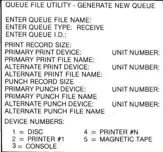
Generate Receive Queue (See Figure 2-3)
QUEUE FILE UTILITY - GENERATE NEW QUEUE
ENTER QUEUE FILE NAME: ENTER QUEUE TYPE: RECEIVE ENTER QUEUE I.D.:
PRINT RECORD SIZE:
PRIMARY PRINT DEVICE: UNIT NUMBER:
PRIMARY PRINT FILE NAME:
ALTERNATE PRINT DEVICE: UNIT NUMBER:
ALTERNATE PRINT FILE NAME: PUNCH RECORD SIZE
PRIMARY PUNCH DEVICE: UNIT NUMBER:
PRIMARY PUNCH FILE NAME
ALTERNATE PUNCH DEVICE: UNIT NUMBER:
ALTERNATE PUNCH FILE NAME DEVICE NUMBERS:
1
=
DISC2
=
PRINTER #1 3 = CONSOLE4
=
PRINTER #N 5 = MAGNETIC TAPEFigure 2-3. Generate Receive Queue
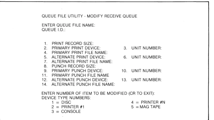
File$ that are received with a printer designation are routed according to the Print File information in the receive queue file. This information includes the record length (usually 132 characters), the primary print device, unit number, and file name; and the alter-nate print device, unit number, and file name.
Normally, any print files received will be routed to the primary print device. If that device is not available, the file will be sent to the alternate print device. For ex-ample, assume that the primary print device is Printer No. 1 and the alternate is the disc, file name "RCVOOO". Received files with a printer routing would be sent to printer No. 1 unless it was busy or out of order. In that case, the files would be sent to "RCVOOO" on the disc and could be printed later.
Also included in the receive queue file is routing in-formation for punch data. The operator must enter the primary punch device, unit number, and file name; and the alternate punch device, unit number, and file names.
The devices available for receive files are disc, printer No.1, printers No.2 through N, console, and magnetic tape.
NOTE
All receive disc file names must be in the format AAAN N N: th ree alphabetic characters followed by three numeric' characters. Two character system device names will automatically be generated for Console, Printer No. 2 through N, and Magnetic Tape based on the previously entered device' type and device unit number. Printer No.1 is a special case and will generate both unit number and two-character device name when device type is selected.
Add Entry To Transmit Queue (See Figure 2-4)
This phase of the program allows the operator to QUEUE FILE UTILITY - ADD ENTRY TO
TRANSMIT QUEUE
ENTER QUEUE FILE NAME: QUEUE I.D.:
ENTRY nnn
ENTER DEVICE TYPE:
ENTER DEVICE UNIT NUMBER: ENTER FILE NAME (CR TO EXIT): ENTER DATA TYPE:
ENTER INITIAL TRANSMIT STATUS:
SHOULD THIS FILE BE CHAINED TO NEXT ENTRY (YIN)?
Figure 2-4. Add Entry to Transmit Queue
add one or more entries at the end of an existing transmit queue. New entries may only be added at the end.
The program will prompt the operator to enter the transmit queue file name desired. The name can be up to six characters long. If a carriage return is entered, the program will returnto the program mode selection menu (Figure 2-1). .
ENTER QUEUE FILE NAME:
If the queue selected is not a transmit queue, or does not exist, an error message will be displayed. Otherwise the queue I. D. will be displayed.
Modify Transmit Queue Entry
This phase of the program allows the operator to change existing records in a transmit queue file.
The program will prompt the operator to enter the name of the queue field to be modified.
ENTER QUEUE FILE NAME:
Up to six characters may be entered. If a carriage return is entered, the program will return to the pro-gram mode selection menu (Figure 2-1).
If the queue file selected is not a transmit queue, an error message will be displayed. Otherwise, the queue I.D. will be displayed.
The program will prompt the operator to enter the number of the next file in the queue to be transmitted. If a carriage return is entered, the current value will be left unchanged.
The program will read each entry in the queue and display the entry number and the data file name. Each entry will be numbered (See Figure 2-5).
QUEUE FILE UTILITY - MODIFY TRANSMIT QUEUE ENTRY
ENTER QUEUE FILE NAME: QUEUE 1.0.:
NEXT ENTRY TO BE TRANSMITTED: ENTRY #
1
2
3
n
FILE NAME xxxxxx
ENTER ENTRY NUMBER TO BE MODIFIED (CR TO EXIT):
Figure 2-5. Entry Number and File Name (Modify)
DATE TITLE 2780/3780 SIMULATOR SYSTEM REFERENCE MANUAL PAGE
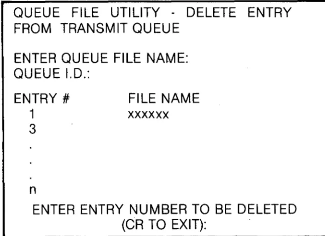
The program will prompt the operator to define which of the records is to be modified.
ENTER ENTRY NUMBER TO BE MODIFIED:
The program will read the selected record and display its contents. If a carriage return is entered as a response, the program will return to the program mode selection menu (Figure 2-1). Each item displayed will be numbered (see Figure 2-6).
QUEUE FILE UTILITY - MODIFY TRANSMIT QUEUE ENTRY
ENTER QUEUE FILE NAME: QUEUE I.D.:
ENTRY nnn
1. 2. 3. 4. 5. 6. 7. B. 9.
FILE NAME:
TRANSM IT STATUS: DEVICE TYPE:
DEVICE UNIT NUMBER: FILE CHAIN:
DATA TYPE:
LAST PHYSICAL RECORD: LAST LOGICAL RECORD: FILE HISTORY: '
ENTER NUMBER OF ITEM TO BE MODIFIED: (CR TO EXIT):
Figure 2-6 Selected Record Contents (Modify) The program will prompt the operator for the item number he desires to modify.
ENTER NUMBER OF ITEM TO BE MODIFIED:
The operator will then be prompted to enter the new value for the field selected. If a carriage return is entered instead of an item number, the program will return to ENTER QUEUE FILE NAME to allow another record to be modified.
Each time an item in an entry is modified, the display of that record