Dense packings of spheres in cylinders: Simulations
A. Mughal
Institute of Mathematics and Physics, Aberystwyth University, Penglais, Aberystwyth, Ceredigion, Wales, SY23 3BZ, United Kingdom
H. K. Chan, D. Weaire, and S. Hutzler
Foams and Complex Systems, School of Physics, Trinity College Dublin, Dublin 2, Ireland (Received 15 March 2012; published 11 May 2012)
We study the optimal packing of hard spheres in an infinitely long cylinder, using simulated annealing, and compare our results with the analogous problem of packing disks on the unrolled surface of a cylinder. The densest structures are described and tabulated in detail up toD/d=2.873 (ratio of cylinder and sphere diameters). This extends previous computations into the range of structures which include internal spheres that are not in contact with the cylinder.
DOI:10.1103/PhysRevE.85.051305 PACS number(s): 45.70.−n, 64.75.Yz, 81.16.Rf, 87.18.Hf
I. INTRODUCTION
The dense packing of monodisperse (equal-sized) hard spheres in a cylinder has been found to produce a remarkable sequence of interesting structures as the ratio of the cylinder diameter to the sphere diameter is varied. We have explored computationally the densest of these packings in detail using simulated annealing, following the work of Pickettet al.[1], and the first four packings in this sequence are shown in Fig.1. We have reported extensive results, together with analytic approximations which serve to elucidate our findings [2]. The present paper and its future continuations amplify the previous reports by Mughalet al.[2] and by Chan (second author of the present paper) [3], and extend them in various directions. In particular, new results are provided for larger cylinder diameters and we include full details of all structures in a form suitable for future reference.
We shall refer to these quasi-one-dimensional (quasi-1D) packings ascolumnar crystals since they are periodic; each structure can be assembled by stacking unit cellsad infinitum along the length of the cylinder with each subsequent unit cell rotated by the same twist angle with respect to the previous one. For smaller cylinder diameters, up to and beyond the range investigated by Pickettet al. [1], the densest packings only consist of spheres that are in contact with the surface of the cylinder. Eventually at larger cylinder diameters dense packings are found for which there are internal spheres that are not in contact with the surface. Nevertheless we extend the study of structures with only cylinder-touching spheres to larger diameters, for its own sake. As already explained in Ref. [2], these structures are readily understood by recourse to a yet simpler problem, in which circular disks are placed on a cylinder. This can be fully worked out in analytical terms.
In parallel with our computational study using simulated annealing and a separate investigation by Chan [3] using sequential deposition, a number of experiments have been undertaken on the packing of solid spheres and small bubbles under gravity. Many of the simulated structures are observed. While we will have cause to mention these experiments, their presentation will be reserved for a later paper [4].
Some of the structures that we describe (particularly the more elementary ones) have been observed in biological microstructures [5]. Columnar crystals have also been realized
in numerous experimental contexts including foams (both dry [6–10] and wet [4]) in tubes, colloids in microchannels [11–15], and fullerenes in nanotubes [16–18]).
We have not attempted to rigorously prove that the densest packings identified by simulations are indeed the densest possible. This ought to be achievable for some of the simplest ones.
II. MOTIVATION AND BACKGROUND
The identification of dense packings has always played an important part in condensed matter physics and physical chemistry [19]. The entities which are to be packed are often spherical, or well approximated as such, and they may be monodisperse. In the idealized case of hard spheres (with no interaction when not in contact) the problem of finding the maximum density with given boundary conditions constitutes a classic mathematical challenge. If posed for an unbounded packing, it is long associated with the name of Kepler [20].
Here we are concerned with the case in which spheres of diameterd are to be contained in an unbounded cylinder of diameter D. We shall pursue it up to D/d=2.873 which represents the limit of the capability of our present computational resources and methods.
Our primary objective is to identify the structure with the largest value of, defined as the fraction of volume occupied by the spheres.
There are close connections between this topic and that of phyllotaxis, a subject arising out of biology and having to do with the dense arrangement of similar units on the surface of a cylinder, exemplified by pine cones, pineapples, or corn cobs [21]. This connection will be explored in detail here.
A. MUGHAL, H. K. CHAN, D. WEAIRE, AND S. HUTZLER PHYSICAL REVIEW E85, 051305 (2012)
FIG. 1. (Color online) The first four densest sphere packings in a cylinder.
The first five of these special solutions, labeledCN, are
shown schematically in Fig.2and (forN >2) consist of disks placed at the vertices of a regular polygon. The diameter of the enclosing circle is given by
Dc(N)=
d if N =1,
d1+sin(π/N1 ) if N 2, (1)
where Dc(2)=2d, Dc(3)=2.1547d, Dc(4)=2.4142d,
Dc(5)=2.7013d.
Replacing the circles withN spheres we define a unit cell which can be repeated along the length of the tube as follows. Each successive layer, indicated by alternating yellow (light gray) and blue (dark gray), can be generated by translating the previous layer through a distance,
Lc(N)= d
if N =1,
d
2
3−(1(1−+cos(cos(π/Nπ/N)))) if N 2, (2)
along the tube and rotating it by a twist angleαc(N)=π/N.
Using the above formula the volume fraction of these simple columnar crystals can easily be computed, (1)= 2/3,(2)=0.4714,(3)=0.5276,(4)=0.5441,(5)= 0.5370.
We shall label these simple columnar crystals with the notation CN to indicate that their structure can be derived
in a simple way from the circle packing problem.
IV. SIMULATION
For general values ofD/d, the optimal packing structure cannot be guessed easily and we must turn to heuristic methods. Our search method is confined to structures that are periodic in the following sense. There is a primitive cell, of lengthL, containingN spheres, the structure being generated
FIG. 2. (Color online) (Top) The first five solutions of the circle packing problem. (Bottom) Five columnar structures corresponding to the first five solutions of the circle packing problem. The unit cells are shown in yellow (light gray) and blue (dark gray).
from this by the screw operation of (i) translation along the cylinder axis by nL (where n is any integer) combined with (ii) rotation about the axis by an anglenα. This screw operation represents the underlying symmetry of columnar crystals (which are not to be confused with columnar phases, originating in the study of liquid crystals and related instead to the packing of columns).
[image:2.608.326.542.68.531.2] [image:2.608.112.229.71.318.2]TABLE I. Specification of densest structures, up toD/d=2.873. Bold numerals designate the line-slip type (see text section VII A). The break in the table denotes the point beyond which packings with internal spheres are observed.
Number of spheres Average contact
Structure Range in unit cell Notation number Description Chirality
1 (C1) D/d=1 1 Straight chain 2 – Achiral
2 1D/d1.866 1 Zigzag 2 – Achiral
3 1.866D/d1.995 1 Twisted zigzag 4 – Chiral
4 1.995D/d <2.0 2 (2,1,1) 4 Line-slip Chiral
5 (C2) D/d =2.0 2 (2,2,0) 5 Maximal contact Achiral
6 2.0< D/d2.039 2 (2,2,0) 5 Line-slip Chiral
7 D/d=2.039 1 (3,2,1) 6 Maximal contact Chiral
8 2.039D/d2.1413 2 (3,2,1) 5 Line-slip Chiral
9 2.1413D/d <2.1545 3 (3,2,1) 16/3 Line-slip Chiral
10 (C3) D/d=2.1547 3 (3,3,0) 6 Maximal contact Achiral
11 2.1547< D/d2.1949 3 (3,3,0) 16/3 Line-slip Chiral
12 2.1949D/d2.2247 2 (3,2,1) 5 Line-slip Chiral
13 D/d=2.2247 2 (4,2,2) 6 Maximal contact Achiral
14 2.2247D/d2.2655 2 (4,2,2)\(4,2,2) 5 Line-slip Chiral
15 2.2655D/d2.2905 3 (3,3,0) 16/3 Line-slip Chiral
16 D/d=2.2905 1 (4,3,1) 6 Maximal contact Chiral
17 2.2905D/d2.3804 3 (4,3,1) 16/3 Line-slip Chiral
18 2.3804D/d <2.413 4 (4,3,1) 11/2 Line-slip Chiral
19 (C4) D/d=2.4142 4 (4,4,0) 6 Maximal contact Achiral
20 2.4142< D/d2.4626 4 (4,4,0) 11/2 Line-slip Chiral
21 2.4626D/d2.4863 3 (4,3,1) 16/3 Line-slip Chiral
22 D=2.4863 1 (5,3,2) 6 Maximal contact Chiral
23 2.4863D/d2.5443 3 (5,3,2) 16/3 Line-slip Chiral
24 2.5443D/d2.5712 4 (4,4,0) 11/2 line-slip Chiral
25 D=2.5712 1 (5,4,1) 6 Maximal contact Chiral
26 2.5712D/d2.655 4 (5,4,1) 11/2 line-slip Chiral
27 2.655D/d <2.7013 5 (5,4,1) 28/5 line-slip Chiral
28 (C5) D/d=2.7013 5 (5,5,0) 6 Maximal contact Achiral
29 2.7013< D/d2.71486 5 (5,5,0) 28/5 line-slip Chiral
30 2.71486D/d <2.7306 6 (1,5) 26/6 −(1,5) Chiral
31 D/d=2.7306 6 (1,5) 40/6 Maximal contact Chiral
32 2.7306< D/d2.74804 6 (1,5) 26/6 +(1,5) Chiral
33 2.74804D/d <2.8211 11 (1,10) 40/11 −(1,10) see Sec.VIII
34 D/d=2.8211 11 (1,10) 60/11 Maximal contact Achiral
35 2.8211D/d <2.8481 11 (1,10) 58/11 +(1,10) Chiral
36 2.8481D/d <2.8615 7 (2,5) 32/7 −(2,5) Chiral
37 D/d=2.8615 7 (2,5) 34/7 Maximal contact Chiral
38 2.8615D/d2.8711 7 (2,5) 30/7 +(2,5) Chiral
39 2.8711D/d2.873 15 (2,13) 72/15 −(2,13) Chiral
40 D/d=2.873 15 (2,13) 90/15 Maximal contact Chiral
positions as variables. It does this for increasing values of
N until the (likely) optimal structure is apparent, or further computation is not practical.
In the previous simulations of Pickettet al.[1], a periodic boundary condition without any twist was used. If, for example, the densest structure has a twist angleαequal toπ/5, then 10 cells would combine to satisfy the simpler boundary condition.
V. NUMERICAL RESULTS
In this section we present the full range of results for several significant properties as a function ofD/d. These include the volume fraction and chirality, for the densest structures that
we have found. The following figures and TableIsummarize the main results.
TableIenumerates all the densest packings observed, from our numerical work, in the range 1D/d2.873. The table lists the range of D/d over which each structure is observed, the number of spheres in the primitive unit cell (from which the extended structure can be constructed), and the average number of contacts per sphere. The table also classifies the structures into two groups: those which are chiral and those which are not (achiral)—see below for a more detailed discussion of chirality.
A. MUGHAL, H. K. CHAN, D. WEAIRE, AND S. HUTZLER PHYSICAL REVIEW E85, 051305 (2012)
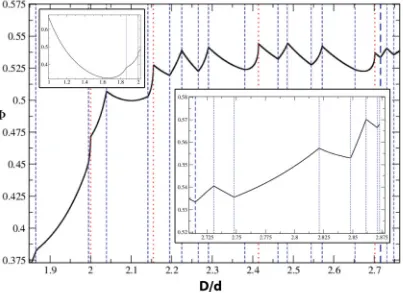
FIG. 3. (Color online) Volume fraction of the densest packing as a function ofD/d. Discontinuities in the derivative are indicated by vertical lines. Red dotted lines indicate solutions to the circle packing problem. The main graph shows results in the range 1.8< D/d <2.71486; the inset are continuations of the same graph showing the regions 1< D/d <1.8 (left) and 2.71486< D/d <2.873 (right). Structures above D=2.71486 include internal spheres while those below do not; the division between these two regions is denoted by a heavy blue dashed line. with the cylindrical boundary. The unit cell for packings
with internal spheres are described using the notation (u,v), where the first integer is the number of internal spheres and the second is the number of spheres which are in contact with the cylindrical boundary. So, for example, in the case of structure 30 the unit cell contains six spheres of which five are in contact with the cylindrical boundary and one is not.
A. Volume fraction
Figure 3 presents the maximum density found by our prescribed procedure, for the full range of D/d that we have explored. A discussion of the method we use to compute the volume fraction is given in Appendix A. By simple finite difference we approximate the derivative of the volume fraction as a function ofD/d, as shown in Fig.4. This is to clearly identify the singular behavior discussed below.
The vertical lines indicate a discontinuity in the derivative of the volume fraction; there is either (i) only a sudden change in the derivative, or (ii) the simultaneous presence of such a sudden change and a square-root singularity in the derivative, the two cases of which are denoted by vertical blue-dashed and red-dotted lines, respectively. Note the square-root singularities in the derivative coincide with the CN (circle
packing) structures.
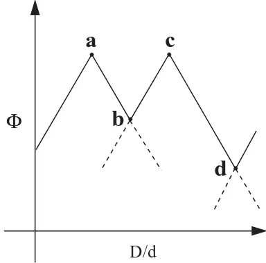
Let us discuss this behavior by reference to Fig.5 which is a simplified cartoon of the observed changes in the volume fraction as a function ofD/d. Qualitatively, the variation of the
maximum density takes the following form: Its dependence on D/d is everywhere continuous while the derivative is piecewise continuous. We distinguish two types of singular points, as in Fig.3, at which the derivative changes.
The first occur when a maximum number of contacts is reached. These points correspond to highly symmetric structures, such as the Cn structures described above. At
such points—represented by the vertices labeled a and c, in Fig. 5—the previous trend of structural change cannot
[image:4.608.105.508.73.366.2] [image:4.608.313.559.551.726.2]Φ
a
c
b
d
[image:5.608.73.265.74.264.2]D/d
FIG. 5. A schematic representation illustrating variations in the volume fraction of the densest packing arrangements as a function of D/d(see text).
be continued; in effect, the structure hasjammeddue to the formation of new contacts. In other words, if the separations of contacting sphere centers is to be maintained, the system is overconstrained and no such solution exists beyond this point. Instead, some existing contacts are released and a new structural trend proceeds. The structure itself varies continuously through the singular point, with a downward change in the derivative of the density, corresponding to the line segmentsabandcdin the cartoon.
At the second kind of singular point the structure is simply overtaken by another more dense packing. Here the structure itself changes discontinuously, and the derivative obviously must change in a positive sense. In Fig. 5 this transition corresponds to the points labeledbanddwhere, for example, the line segmentbcillustrates the increasing trend in density immediately following such a transition. The dashed lines indicate the continuation of the previous structure which now has a lower density compared with the optimal packing.
These remarks are based on observation of the results. We have, for example, no proof that the change of derivative at points of the first type is always negative, although we can offer a proof that the dependence of (maximum) density onD/d
cannot have any discontinuities at which the density undergoes a finite upward or downward change. This is discussed in detail in Appendix C.
B. Chirality
A chiral object is one which cannot be superimposed on its mirror image (or inverse) by translations and (proper) rotations. The question of chirality is interesting in the present context, for example, in relation to designing chiral molecular filters that will discriminate between enantiomers.
According to this definition an object is either chiral or it is not (it is achiral). The reported structures are classified accordingly in TableI.
But chirality may be manifested in physical properties to a greater or lesser extent: The degree of chirality of the structure itself is a tempting concept. While it may be useful to think of
this in practice, there is no unique quantitative definition that will have general relevance. Anyappropriate property could be used as an index of chirality. Nevertheless one may offer a working definition for use in relation to simulations, as Pickett et al.did [1]. Here we will employ another definition that is perhaps more transparent.
We define a chirality index χ in terms of the degree to which an object can be superimposed upon its mirror image. For a given columnar crystal, our method is to start with the sphere centers and generate a mirror image of the structure by reflecting the coordinates of the centers in thex-yplane (i.e., the cross-sectional plane of the cylinder). For each sphere in the packing we compute its distance to the nearest sphere in the mirror image. The overlap function is defined as the sum of these distances divided by the number of spheres in the original packing. Clearly when a packing can be completely superimposed upon its mirror image the overlap function vanishes.
The computational challenge then is to find the arrangement of the mirror image (by rotation and translation) that minimizes the overlap with respect to the original structure. This is done in a straightforward manner by simulated annealing. Clearly for chiral structures the overlap cannot vanish and by plotting the overlap function we have a measureχof the chirality as a function ofD/d, as in Fig.6.
VI. DETAILS OF STRUCTURES FORD/dUP TO 2.71486 Up toD/d=2.71486, all the structures that are found are of a special character, helpful for their interpretation. Every sphere is in contact with the cylinder surface. Therefore all of their centers lie on an inner cylinder, of diameterD-d, and they touch another cylinder of diameterD-2d. They may therefore be considered as the densest packings of spheresona cylinder. Clearly inner spheres must appear in the optimal packing when D-2d is greater than d, that is,D >3.0, in fact they are first found atD/d >2.71486, and we reserve them for a separate discussion in the next section. We also treat structures for lowD/dseparately in Sec.VI C.
A. Maximal contact structures
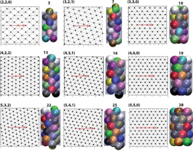
We have already noted the special points at which the structure changes continuously, with the formation of new contacts and the breaking of old ones. We have previously called themsymmetricstructures, but this term is really only meaningful in the disk-packing analysis below. Here we shall apply the termmaximal contactinstead. ForD/d2, all of these structures are depicted in Fig.7 and labeled using the phyllotactic notation explained in AppendixB.
They include the simpleCnpackings which we have already
described and are labeledn,n,0 in the phyllotactic notation (see AppendixB). This relates to the pattern of sphere centers and contacts, “rolled out” onto a plane, and identified with rhombic or triangular lattices. This does not apply to the first of the structures, the straight chain, and is rather confusing if applied to the next two, hence we use it only for the subsequent structures.
A. MUGHAL, H. K. CHAN, D. WEAIRE, AND S. HUTZLER PHYSICAL REVIEW E85, 051305 (2012)
FIG. 6. (Color online) A plot of the chiral indexχ(D/d), which measures the degree of mismatch between a packing and its mirror image (see text). Vertical lines indicate structural transitions as in Fig.3. The main graph on the left shows results in the range 1.8< D/d <2.71486 while the graph on the right is a continuation but focuses on the region 2.71486< D/d <2.873.
has five contacts (not including contact between a given sphere and the cylinder); these consist of a contact with the neighboring sphere in the same unit cell and four contacts with spheres in adjacent cells. All of the rest of the maximal contact structures so far considered are composed of spheres with six contacts. Packings of the typeCnare achiral while the rest are
chiral.
B. Line-slip structures
We now turn to the intervening structures, which are modified versions of the maximal contact packings, adjusted to fit around the cylinder. Such staggered heliceswere first observed by Pickettet al.in their simulations [1]. We label these line-slip structures to indicate that the modification consists of the release of half of the contacts along one line separating two of the spiral chains of the symmetric structure, and a consequent relative slip of the two sides. Such line-slip arrangements are a feature of hard sphere packings and are evident in the rolled out patterns of Fig.8.
There are in general three possible choices for the direction of the line slip and the results of Fig.8 correspond to those that maintain the highest density as in Fig.3.
We continue to higher values ofD/din Sec.VIII.
C. Structures belowD/d=2.0, and the square root singularity We return to examine the structures for lowD/d, which are somewhat different. The reason for such a difference will become clearer when we explore the relationship to disk packing, in a later section. These first four structures are shown in Fig.1.
Structure 1 is the elementary case of a straight chain of spheres, like peas in a pod, as shown in Fig. 1. This trivial, achiral structure has a volume fraction of(1)=2/3. Similarly structure 2 is obvious and consists of a zigzag planar arrangement of spheres such that the change of the azimuthal angle from one ball to the next is equal toπ; each sphere makes
contact with one sphere from above and one from below. When the zigzag packing (i.e., structure 2) encounters additional contacts between its second neighbours atD/d =1.886 (so that each sphere now has four contacts), it is forced to take the form of an increasingly twisted spiral (structure 3). By direct numerical calculation one may follow this to its end point at structure 7, but structure 6 intervenes with higher density, so that there must be a transition belowD/d= 2.0. This is found at D/d =1.995, strikingly close to 2.0, beyond which the densest packing is a line-slip modification of structure 6. The smallness of the interval in which this is found is largely due to the existence of a square-root singularity.
The variation of volume fraction, as any of the Cn or
n,n,0 structures is approached with increasingD/d, exhibits a square-root form, whereas it is linear in other cases; that is,
0−≈
D0
d0
−
D d
1/2
, (3)
where the quantities with a subscript 0 belong to aCnorn,n,0
structure. The derivative plot shown in Fig. 4is intended to make this singular behavior more evident. The square root arises from the special symmetry of these achiral structures.
VII. RELATIONSHIP TO CIRCULAR DISK PACKINGS ON A CYLINDER
Many aspects of these results are made more understand-able by recourse to the packing of circular disks on a cylinder. We have already noted that the same sequence of symmetric structures is found. The similarity extends further to the line-slip structures and some of the details of the analytic form of the curve in Fig.3(not yet noted).
[image:6.608.105.510.74.271.2]FIG. 7. (Color online) Maximal contact structures, with the corresponding “rolled-out” pattern of contacts. The vectorV(corresponding to the perimeter of a cylinder cross section) is indicated by the red arrows.
A. Disk packings
Densest packing of circular disks in a plane places their centers on a triangular lattice where each disk has six contacts; this was rigorously proved about a century ago [19]. Cylindrical surface packing of disks with the same density is generated by rolling this pattern onto a cylinder, when possible. To see how this can be achieved seamlessly let us define a periodicity vectorVbetween any pair of disk centers of the triangular lattice packing as shown in Fig.9(a). The region between the start and end ofV, which is bounded by lines perpendicular to V, can then be excised and wrapped onto a cylinder whose circumference is equal to the length ofV. The resulting structure is a dense, homogenous packing— in the sense that all disk sites are equivalent—which we call a symmetric packing. Any such symmetric packing is characterized by this periodicity vector. In the phyllotactic schemeVcan be defined by a set of three ordered positive integers (l=m+n,m,n), as discussed in Appendix B [a simple operational method to assign indices is to count the number of lattice rows that cross the periodicity vector in the three directions, as shown in Figs.9(a)and9(c)].
For other values of the cylinder circumference, the sym-metric packing may be distorted in some way to wrap around the cylinder. The most obvious adjustment is an affine transformation of the triangular lattice, as shown in Fig.9(b). We illustrate the effect of the transformation by reference to the shaded triangle in Fig. 9(a). The affine transformation distorts the equilateral triangle into an isosceles triangle by keeping the length of two adjacent sides fixed and varying the
third; consequently, the disk centers form a rhombic lattice which has a lower density (area fraction) compared with the triangular lattice since each disk now has only four contacts (the lowest area fraction corresponds to a square lattice). The transformation may be adjusted to make the length ofV equal toπ D. The resulting pattern can be wrapped onto the surface of the cylinder. We may call these asymmetric or affine lattice packings.
If D/d is varied the disk centers of such a structure are eventually brought back into coincidence with the sites of a triangular lattice; see Fig. 9(c). In this manner the strained structure proceeds from one symmetric packing to another. Since there are three possible choices for the affine transformation, the rules for this process—as reported previously [2]—are, when applied to the second and third phyllotactic indices, as follows:
(m,n)→(m−n,n), (m,n)→(m+n,m),
(m,n)→(m+n,n),
where the new phyllotactic indices may have to be rearranged into descending order.
Intermediate asymmetric packings may be labeled using rhombic notation [p,q], where the ordered indicespq are the indices common to both the initial and final symmetric states. Once again, the integerspandq count the number of lattice rows crossing the periodicity vectorV.
[image:7.608.112.495.72.373.2]A. MUGHAL, H. K. CHAN, D. WEAIRE, AND S. HUTZLER PHYSICAL REVIEW E85, 051305 (2012)
FIG. 8. (Color online) Line slip structures at arbitrarily chosen values ofD/dwithin their respective ranges, with corresponding rolled out patterns of contacts. The vectorVis indicated by an arrow.
the above rules yield
(4,1)→(3,1), (4,1)→(5,4), (4,1)→(5,1).
Thus the symmetric packing [5,4,1] is connected to [4,3,1] via the rhombic structure [4,1], to [9,5,4] via [5,4]—which are shown in Figs.9(c)and9(b), respectively—and to [6,5,1] via [5,1].
Although such asymmetric packings are the simplest type of dense structure, intermediate between two symmetric packings, they are not the densest. As reported previously [2], asymmetric packings are in general superseded by another type of packing involving an inhomogeneous shear of the symmetric lattice in which there is a localized strain or slip along a line (and its periodic replicas).
[image:8.608.54.558.72.540.2]FIG. 9. (Color online) (a) symmetric packing [5, 4, 1], the black arrow represents the periodicity vector; (b) the square packing [5, 4]; (c) the symmetric packing [9, 5, 4] which is connected by an affine shear to [5, 4, 1]; (d & e) show a line slip connecting [5, 4, 1] to the symmetric packing [6, 4, 2], which is shown in (f).
is connected to [5,3,2] and [5,5,0]. In the third case only a single lattice row crosses the periodicity vector and we find that [5,4,1] is connected to [6,5,1] and [4,3,1].
This localized shear allows the length of V to vary continuously. The disks involved in the line slip have five contacts while the rest of the structure remains symmetric and close-packed, with six contacts for every disk. Clearly the surface density of disks has a maximum, corresponding to the symmetric packings, while the intermediate line-slip packings have a lower value. As reported previously [2], there is a simple rule for the close-packed structures that are the end points of line-slip solutions,
(1) (m,n)→(m+1,n) or (m−1,n),
(2) (m,n)→(m,n+1) or (m,n−1),
(3) (m,n)→(m+1,n−1) or (m−1,n+1),
where the leading numbers denote the directiona1,a2ora3 of the line slip. Again the above rules apply to the second and third phyllotactic indices of a given close packed structure and keep eithern,m, orlconstant. For example, using the above rules, the symmetric packing [5,3,2] is connected by a line slip alonga1to [6,4,2] or [4,2,2], a line slip alonga2 yields [4,3,1] or [6,3,3], and a line slip alonga3 yields [5,4,1] or [5,3,2] (note in the third case—alonga3—a rearrangement of
the phyllotactic indices into descending order was necessary and the new structure is the same as the initial structure).
In TableIwe use bold numerals to denote the direction of the line slip. In the table we only have cause to mention the first column of line-slip structures, that is, we denote
(1) [l,m,n]→[l+1,m+1,n] by [l,m,n],
(2) [l,m,n]→[l+1,m,n+1] by [l,m,n],
(3) [l,m,n]→[l,m+1,n−1] by [l,m,n].
A full derivation of such connection rules for both the asymmetric and line-slip packings will be given in a future publication.
Figure 10 presents analytical results for the density of these disk packings. Here we see for the first time some of the structures of lower density, as well as those of maximum density. Even at this stage, we find a qualitative resemblance between Fig.10, the disk packing problem, and the corresponding sphere packings (as shown in Fig.3).
[image:9.608.56.554.72.401.2]A. MUGHAL, H. K. CHAN, D. WEAIRE, AND S. HUTZLER PHYSICAL REVIEW E85, 051305 (2012)
FIG. 10. (Color online) Surface density of disk packings on the plane which are consistent with wrapping onto a cylinder of diameter |V|/π. Asymmetric packings are shown by (red) dashed curves; line-slip solutions are (black) continuous curves. Symmetric structures labeled [l,m,n] correspond to points of maximum density while intermediate asymmetric packings are labeled using the rhombic notation [p,q].
with the surface of the inner cylinder bears a close resemblance to the disk packing problem, which we now consider in detail.
B. Relation to sphere packing
We now explore more closely thequantitative correspon-dence between disk and sphere packings, and find a way of bringing them as close to each other as is possible without undue complication.
Consider again a packing of spheres, all touching the confining cylinder of diameterD. Their centers lie on an inner cylinder of diameter D=D−d, so that a given center is located at (D/2,θ,z) in cylindrical polar coordinates. The separation of contacting spheres in three dimensions is d
but if the inner cylinder is rolled out onto the plane [i.e., a given sphere center is mapped to the 2D cartesian coordinates (s=Dθ/2,z)], then the distance between the centers of contacting spheres in two dimensions depends on their mutual orientation.
In general, the required contact rule, in three dimensions, for a pair of spheres (each having diameterd) whose centers, in cylindrical polar coordinates, are located atr1=(D/2,θ,z) andr2=(D/2,θ+θ,z+z) is [3]
(z)2+D 2
2 (1−cosθ)=d
2. (4)
We plot the parametric equation [Eq.(4)] in Fig.11for various values ofD/d[where the distances≡(D/2)θis referred
to as the “arc length”]. We see that, asD/d increases above 2, the “surface packing” resembles the packing of oval disks, which may be approximated by ellipses. For contacting spheres that lie directly in a line parallel to the direction of the cylinder axis, the separation of their centers is stillS||=d, while for
[image:10.608.103.508.72.363.2] [image:10.608.341.525.528.715.2]FIG. 12. (Color online) Comparison of simulated and analytic volume fractions for the densest packings—upper and lower curves, respectively. Dotted lines are a guide for the eye to the detailed correspondence. In the analytic results, the line-slip structures are identified by black continuous lines, and the red dashed-dotted lines denote asymmetric packing structures. The numbers 1, 2, and 3 (see text) denote the type of line slip observed (upper curve) or predicted (lower curve) with 1\2 denoting a degenerate case. The shaded region on the right is the continuation of the single layered structures forD/d >2.71486.
those that lie in the perpendicular plane, it is
S⊥=Dsin−1
d D
. (5)
For simplicity we take the major and minor axes of the ellipse to have theS⊥andS||, so that the distance on the plane for a pair of contacting spheres is approximated by
S2=d2sin2(φ)+ Dsin−1
d D
2
cos2(φ). (6)
Comparing the circumference of the inner cylinder π D
with the length of the periodicity vector|V|d (i.e., measured in units of the disk diameterd), gives a stretch factor,
X= π D
|V|d =
S⊥
d , (7)
where the last term is the ratio of the arc distance between contacting spheres, which lie perpendicular to the direction of the cylinder axis. In this way the sphere packing is related to the planar packing of elliptical disks, which is merely a stretched version of a circular disk packing. Given any packing of circular disks in the plane, it may simply be stretched in the direction of the vectorV, by a factorX, and wrapped onto a cylinder of diameter,
D= d
sin(π/|V|), (8)
[obtained using Eqs.(5)and(7)], to create a good approxima-tion to a sphere packing.
Thus a correspondence that at first seems distant may be brought much closer. Figure 12 presents the resulting transformed curves for sphere packing density; asymmetric and line-slip structures are shown by red (dashed) and black (continuous) lines, respectively. The peaks in the density correspond to symmetric packings. The lower (dashed) heavy black line accentuates the curve of maximum density, as predicted by our analytical approach. This is to be compared with the results of simulated annealing shown by the upper curve. We have extended our simulated annealing study of single layer packings toD >2.71486, as shown by the gray region in Fig. 12, by searching for the densest structures in which all the spheres have centers on the surface of a cylinder of diameterD. From this we see that the maximum possible density, for single layer packings, is found at (2.4863)= 0.5446 and corresponds to the symmetric packing (5,3,2). Beyond this the packing density steadily diminishes since spheres are to be found only on the surface of the cylinder and the interior is empty.
[image:11.608.104.507.71.368.2]A. MUGHAL, H. K. CHAN, D. WEAIRE, AND S. HUTZLER PHYSICAL REVIEW E85, 051305 (2012) predict type (3) line-slip solutions leading up ton,n,0 packing
while simulations in fact find a region split between a type (2) line slip followed immediately by a type (3) line slip. A more accurate (and more complicated) transformation ought to account for this by pushing the type (2) curve above the type (3) solution, for part of this region. This is borne out by the fact that as the diameter of the cylinder increases, and higher order corrections to the transformation diminish in importance, the type (2) solution in the simulations are observed over an increasingly smaller range in the split region.
VIII. STRUCTURES BEYONDD/D=2.71486, WITH INTERNAL SPHERES
We are able to pursue the same simulations to higher cylinder diameters, finding the anticipated occurrence of internal spheres, initially at D/d=2.71486. The structures involved are tabulated in the final section of TableI. In some cases phyllotactic notation may still be useful, but much of the simplicity of the previous sections is lost, and increasingly so. The extension of the curve of volume fraction, as far as present computing resources allow, is shown on the right-hand side of Fig.3.
It is of the same general character as before; that is, we observe peaks corresponding to maximal contact structures— which are labeled using the notation (u,v) in TableI— and decreasing or increasing D/d yields structures with fewer contacts which can in some way be deformed steadily into the maximal contact packing; these are labeled−(u,v) and
+(u,v), respectively.
Packings with internal spheres are depicted in Fig.13where in each case the middle diagram shows the entire structure viewed side-on. Although the introduction of inner spheres produces more complicated structures there remains an outer shell of spheres contacting the confining cylinder. The rolled-out pattern made by these rolled-outer spheres is shown to the left of each packing. The arrangement of the inner spheres is depicted in the diagram to the right of each packing, whereby the outer layer is transparent and the inner spheres are in yellow.
The first packing with internal spheres is structure 30, or −(1,5), which consists of a basic unit cell containing six spheres. Of these one sphere is not in contact with the cylindrical surface and is found at the center of the cylinder. The remaining five spheres, which are in contact with the cylinder, form a tilted pentagonal ring around the central sphere (i.e., tilted at an angle with respect to the plane perpendicular to the cylindrical axis). The extended structure can be made by translating the unit cell along the cylinder and rotating it byπ. The result is a chiral packing with an internal chain of noncontacting spheres along the cylindrical axis and an outer layer of touching pentagonal rings. As can be seen, in the corresponding rolled-out diagram of the outer layer in Fig.13, there is only a single point of contact between outer rings corresponding to a sphere with four surface neighbors. The location of this sphere alternates by an azimuthal angle ofπ
between successive layers.
Some of the spheres in the outer layer have only two contacts with other spheres in the outer layer. However, mechanical stability is assured by their contact with the internal
chain of spheres and the average number of contacts per sphere for the structure as a whole is above four.
Increasing D/d reduces the tilt of the pentagonal rings until atD/d=2.7306 we have the maximal contact packing (1,5). Thus in structure 31 the spheres in the internal chain are in contact with each other and, compared with structure 30, there are now a greater number of contacts between successive pentagonal rings. IncreasingD/dbreaks some of these surface contacts and forces the chain of internal spheres to form a twisted zigzag structure. Thus structure 32, or+(1,5), is chiral and is superseded atD/d=2.74804 by a new type of packing. Structure 33, or −(1,10), consists of a basic unit cell containing 11 spheres. Of these 10 touch the cylindrical surface and are arranged as a pair of pentagonal rings stacked on top of each other. The 11th, internal sphere is found above the 10 surface spheres and is located at the center of the cylinder. The extended structure can be described as an alternating sequence of surface spheres followed by an internal sphere. However, on average each sphere is only in contact with 40/11=3.636 other spheres; this number is too low for mechanical stability, which we explain as follows.
As shown by the rolled-out diagram of the outer sphere centers, surface spheres from adjacent unit cells are not in contact. Thus the pairs of pentagonal rings are free to rotate, by a certain amount about the cylindrical axis while internal spheres remain fixed in position. Whether structure 33 is achiral or chiral depends on the relative orientation of the surface spheres with respect to each other. No other optimal cylindrical packing yet discovered has this property.
With increasing D/d the pentagonal rings from adjacent unit cells are eventually locked into position atD/d =2.8211 to give (1,10). Thus packing 34 is a maximal contact achiral structure, corresponding to a peak in Fig.3. The spheres in the outer layer form a perfect rhombic [5,5] lattice when rolled out onto the plane and the internal spheres lie along the cylindrical axis. An increase in D/d results in the loss of two contacts (on average) between the surface spheres and the internal spheres, and+(1,10) proceeds downward in density. As the trend continues we observe a decrease in the separation of neighboring internal spheres and a modulation in the rhombic surface pattern; this latter symmetry breaking is responsible for structure 35 being a chiral structure.
Packing 36 includes an internal linear chain of noncon-tacting spheres lying along the central axis of the confining cylinder. These are surrounded by an outer layer of spheres which form a complex chiral structure. AsD/d is increased the spheres in the internal chain are brought ever closer to each other until they make contact atD/d=2.8615, which corresponds to the maximal contact, chiral structure 37.
A further increase in D/d forces the internal chain of spheres to form a twisted zigzag structure. As a result there is a loss of two types of contacts: the breaking of contacts between spheres in the outer layer (as seen from the corresponding rolled-out pattern in Fig.13) and a break in contact between spheres in the outer and inner layer. Thus there is a decrease in density as we proceed from structure 37 along 38 [i.e., as we increaseD/dfor+(2,5)].
FIG. 13. (Color online) Structures with internal spheres. In the case of structures which are not maximal contact the images are produced from numerical results for arbitrarily chosen values ofD/dwithin their ranges. The central image shows each structure viewed side-on. The image on the right shows the inner layer by making the outer layer transparent. The image on the left, for each packing, is the rolled out structure generated by the outer layer of spheres which contact the cylindrical boundary - the periodicity vectorVis indicated by the red arrow. a gap; this is the structure−(2,13). IncreasingD/dproduces
structure 40, a maximal contact chiral packing (2,13), which compared with structure 39 has an increased number of contacts between internal-surface and surface-surface spheres. This remarkable sequence of structures would have been difficult to imagine in advance. It is likely to be followed by an equally rich scenario, whenever it becomes possible to pursue higher values ofD/d. The structures reported are new, to our knowledge, except in so far as they correspond to dry foam structures mentioned below in Sec.X.
IX. RELATED EXPERIMENTS
Columnar sphere packings appear in a variety of different experimental contexts, such as the packing ofC60buckyballs inside carbon nanotubes [16] and polystyrene spheres inside the pores of silicone membranes [14]. The structures that are commonly identified are the straight chain (structure 1 in our TableI), zigzag (structure 2), twisted zigzag (structure 3), and
structure 5, although more complicated structures have also been observed (e.g., [13]).
However, care needs to be taken when directly comparing these experimental observations with the simple hard sphere simulations described here, which might well only serve as a first guide of what structures to expect. The minimization of interaction energy may replace the maximization of density as the guiding principle.
For example, the polystyrene particles in the experiments of [14] have been charge-stabilized and thus repel each other. Unlike the situation in our simulations, this results in a prefer-ence to sit near the wall of the pores (i.e., the cylinder wall).
[image:13.608.57.550.68.456.2]A. MUGHAL, H. K. CHAN, D. WEAIRE, AND S. HUTZLER PHYSICAL REVIEW E85, 051305 (2012) A. Present experiments with ball bearings and bubbles
However, we have identified two other experimental sys-tems that provide very good comparison with our simulation data (details to be provided in a follow-up paper).
The first are metal spheres of a few millimeter in diameter (the type used in “ball bearings”) packed into perspex tubes. The filled tubes were mechanically agitated over an extended period. At the end of this “annealing” procedure this resulted in clearly identifiable ordered sphere packings. These experiments were carried out for a large range of values of
D/d(up to 3.15), and resulted in about 16 different structures, of both the maximal contact and the line-slip type.
We have also carried out more extensive experiments with equal-volume gas bubbles (with diameter of a few hundred microns). These are produced by bubbling gas into surfactant solution with the bubble diameter easily variable by adjusting the gas flow.
The bubbles are then gathered into vertically placed cylinders. They maintain a (nearly) spherical shape, even when in contact, up to a column height of a few millimeters, corresponding to the capillary length for the surfactant solution in use.
We were able to produce straight chain, zigzag, and a large number of maximal contact structures, and also many structures with internal bubbles, up to and well beyond the point reached by the present simulations. There is also some evidence of the twisted zigzag structure and line-slip struc-tures. The subsequent paper presenting these experimentally obtained structures will include the use of x-ray tomography to establish their internal configurations.
B. Ordered dry foam structures
Extensive and detailed results have been published for the various structures that form when equal volume bubbles with diameter exceeding a few millimeters (i.e., larger than the capillary length) are collected in vertical tubes [8,22]. In this case, the liquid drains and adryfoam is created—a packing of polyhedral bubbles, with its volume fractionapproaching unity.
The surface pattern displayed by these ordered foams is hexagonal (apart from the so-called bamboo structure which is simply an array of parallel soap films). The phyllotactic notation is thus the obvious choice for their classification, at least as long as there are no internal bubbles (see, e.g., Fig.14). Restricting ourselves for the moment to this case it would appear thatallordered dry foam structures have corresponding sphere packings (wet foams) (i.e., they can be classified by the same phyllotactic notation). These include the straight chain (bamboo) and zigzag structure (called 2-1-1 or staircase structure in the foam literature), and all of the 10 maximal contact structures, except structure 25 (5-4-1) which has not yet been observed.Noneof the ordered dry foam structures is of the line-slip type.
Note that since the bubbles are deformable, the average contact number in the case of dry foams is generally higher than in hard sphere packings.
Unlike their sphere packing counterparts, the various dry foam structures are found over ranges of values ofD/d (in the foams literaturedrefers to the equivalent sphere diameter
FIG. 14. (Color online) In the dry foam equivalent of the zigzag structure (often called the staircase structure) equal-volume gas bubbles are separated by thin liquid films. (a) Computer simula-tion using the SURFACE EVOLVER software of Ken Brakke [23]. (b) Photograph of bubbles in a cylinder of about 1 cm in diameter. of a bubble). Hysteresis plays a large role in the standard experimental procedure, leading to overlapping ranges of stability for the various structures.
The structure of minimal energy for a given value ofD/d
may be determined from computer simulations [22,24–27]. We find these ranges always to be lower than the value of
D/d for the corresponding sphere packing, reflecting their much smaller volume fractions. It remains for future research to establish the phase diagram (which may be rather complex) that connects these two limiting cases.
There are also observations of over 20 different ordered dry foam structures with internal bubbles [8], but the precise internal arrangements have only been identified for the three simplest cases, with the aid ofSURFACE EVOLVERsimulations [23,26].
The dry foam with a surface pattern equivalent to structure 28 (C5) has six bubbles in the periodic unit cell (i.e., one more thanC5). A pentagonal dodecahedron in the center of the cylinder is surrounded by a ring of five bubbles in contact with the cylinder surface. The dodecahedra of neighboring unit cells are in contact.
There is also a foam structure with a so-called Kelvin cell (tetracaidecahedron) in the center, surrounded by six bubbles in contact with the surface. Again the internal bubbles of neighboring unit cells are in contact with each other.
The third identified structure with internal bubbles consists of a total of 13 bubbles in the unit cell, 12 touching the surface, and a bubble with 12 pentagons and three hexagons (Goldberg-3) in the center [26]. Interestingly, in this case the internal bubbles of neighboring unit cells are not in contact, similar to the also achiral structure 34. The surface pattern of this foam structure consists of an arrangement of bi-disperse hexagons.
X. CONCLUSIONS
[image:14.608.335.529.73.254.2]fall into three categories: the very simplest cases, where the sphere diameter is of the same order as that of the cylinder, a wide range of further “phyllotactic” structures, which may be understood as related to surface packings of disks, and structures that incorporate internal spheres.
Corresponding experimental observations are now avail-able and will be reported in a second paper. Experiments can already be pushed to much larger cylinder diameters, providing further insights and challenges to simulation and interpretation.
Such a further development should motivate a reassessment of the simulation methods to be used; we make no strong claims for the efficiency of that used here. We have necessarily been cautious in using it, stipulating high degrees of convergence and undertaking many repeated runs in search of the optimum, to increase confidence in our conclusions. In parallel studies, Chan [3] used a sequential deposition method that was highly expeditious in determining optimal structures within the restriction of that procedure, whose effect could not be knowna priori. Suitably adapted, it was able to reproduce the structures reported here, up to at leastD/d=2.7013. Future work will include an extension of this deposition approach to higher values ofD/d.
Finally we note some possible extensions to this work. An example is the study of disordered hard sphere packings in a cylinder; for such problems the definition of the volume fraction recently given by Chan [3] may prove useful. A simple problem that may be of significant practical interest is to find the densest packing of hard spheres in a cylinder which is capped on either side by hard walls (i.e., packing in a cylindrical box). Even richer possibilities are offered by packing hard sphere in a cylinder that is capped on both ends by spheres held in a fixed position. Indeed, hard sphere packings that are bounded by templated surfaces on all sides are of significant current interest and are capable of realizing a range of different morphologies (including the Weaire-Phelan structure) [28].
ACKNOWLEDGMENTS
This research was supported by Science Foundation Ireland (Grant No. 08-RFP-MTR1083) and European Space Agency (MAP Grants No. AO-99-108:C14914/02/NL/SH and No. AO-99-075:C14308/00/NL/SH). H.K.C. acknowledges sup-port from the Irish Research Council for Science, Engineering and Technology (EMPOWER Fellowship).
APPENDIX A: SIMULATION TECHNIQUE 1. Energy function
The simulation is addressed to a cylindrically shaped cell of length L and diameter D. Contained within this space areN points which represent the centers ofN spheres, each of diameter d. If a pair of spheres is sufficiently close that they overlap we account for this using a pairwise potential as described below. A similar overlap potential is used to prevent the spheres from escaping the simulation cell in the radial direction. The final structures will be the densest that we find which have zero overlap energy.
In addition, we impose twistedperiodic boundary condi-tions on the top and bottom of the cylindrical cell as described in the main text, with a twist angleα.
We model the overlap potential between spheres using a Hookean, or “springlike,” pairwise interaction between theith andjth spheres, which have their centers atri =(ri,θi,zi) and
rj =(rj,θj,zj); the interaction energy between spheres is then
given by
EijS =
1
2(rij −d)
2 if r
ij d,
0 if rij > d,
(A1)
whererij = |ri−rj|is the distance between the centers of the
spheres. Note the interaction energy falls to zero when there is no overlap between the spheres.
The interaction energy between the ith sphere and the boundary is given by
EiB=
1
2(riB−d/2)
2 if r
iB d/2,
0 if riB > d/2,
(A2)
whereriB = |D/2−ri|.
The twisted periodic boundary conditions on the ends of the cylinder are incorporated as follows: The ith particle in the simulation cell has an image at the top and bottom of the simulation cell; the coordinates of these images are given by r+i =(ri,θi+α,zi+L) and r−i =(ri,θi−α,zi−
L), respectively, whereL is the length of the cylinder and
αis the twist angle.
Thus the total energy of the system is given by the sum of the sphere-sphere, sphere-boundary, and sphere-image interactions.
2. Numerical method
For a tube of diameter D we wish to find the unit cell, composed ofNspheres, which when rotated and stacked along the tube has the highest volume fraction. In this section we describe the simulation protocol used to achieve this.
For a given D andd we assign initial starting positions to theN spheres and an initial value to the twist angleαby using a random number generator. A small initial value for the cylinder lengthLis chosen to ensure overlap between the spheres.
Keeping DandLfixed, we search for the lowest energy arrangement for theNspheres by varying their coordinates and the twist angle. This is done using the standardMETROPOLIS simulated annealing algorithm, where for a cluster of N
spheres the algorithm was run with typicallyN×(5×10⁶) Monte Carlo steps. The temperature of the simulation was decreased linearly. The average displacement of the spheres at each temperature step was chosen by an automatic process to give an acceptance probability of 0.5±0.01. The results of the simulated annealing are then put through a conjugate gradient routine to ensure that a local minimum has been reached.
A. MUGHAL, H. K. CHAN, D. WEAIRE, AND S. HUTZLER PHYSICAL REVIEW E85, 051305 (2012) After this first run we perform a subsequent run with a
slightly longer cylinder. Since the spheres have more room the energy of the final state is lower compared to the final state of the previous run. Using a divide-and-conquer approach we are able to establish the cell length at which the energy per sphere in the system falls to zero; in practice this means the value of the energy is within a critical bound which is set to beE/n=1×10−8±5×10−9. At this point the spheres have a small overlap corresponding to a five decimal place accuracy in the volume fraction (this is deduced by comparing simulation with the analytically derived volume fraction for theCNcircle packing structures).
From this final result we compute the volume fraction which is defined as
(N,D)= N Vs
Vc
, (A3)
where Vs =(4/3)π(d/2)3 is the volume of one of the hard
spheres andVc=π(D/2)2Lis the volume of the simulation
cell. Note that the volume fraction depends on bothD and
N since different values ofN yield unit cells with different structures. Thus the whole procedure is repeated for a series of different values ofN =1,2,3. . ., typically upN =15 for the structures without internal spheres, before accepting the one which gives the largest volume fraction, as shown in TableI.
APPENDIX B: CONTINUITY OF THE VOLUME FRACTION We demonstrate that there can be no sudden finite dis-continuities in the curve describing the maximum volume fraction (density) asD/d is varied. This follows from lower and upper bounds, as described below, which limit the variation in volume fraction in the neighborhood of any pointD0/d0. We will see that square-root singularities observed in the numerical results for the volume fraction are due to the arguments given below.
1. Lower bound
For increasing D/d an obvious variational argument bounds the density below. AsD/d is increased fromD0/d0, the cylinder expands radially. We may take the structure which has maximum density atD0/d0as a trial structure for
D/d > D0/d0. The volume fraction of the structure, atD0/d0, is
(D0/d0)=
Vs
π(D0/2)2L¯, (B1)
and that of the trial structure is
T(D/d)= Vs
π(D/2)2L¯, (B2)
whereVs =Vs(d) is the volume of a sphere of diameterd, and
¯
Lis the average separation between spheres in thezdirection. SinceT(D0/d0)=(D0/d0) it follows that
T(D/d)>D
2 0
D2(D0/d0), (B3)
providing a lower bound forD > D0.
2. Upper bound
For decreasing D/d, a more subtle argument bounds the variation of density below by a square-root function. Decreasing D/d forces the spheres to move radially inward to avoid contact with the cylindrical boundary. The resulting overlap between spheres can be eliminated by displacement of their centers parallel to the cylinder axis.
Let us index the sphere centers in ascending height using the index j so that zj > zj−1 for j > j −1. Given the structure at D0/d0 which has a maximum density, then an extreme case is one where successive spheres all have the same height. Consider in this case a pair of contacting spheres with separationd. Reducing the cylinder diameter by a factor of X, so that the new diameter is D=D0X, will force an overlap so that the separation between sphere centers is now
dX. The overlap can be removed by moving one of the spheres vertically a distance, so that their separation is once again
d. It follows thatd2=2−(dX)2. Thus a constantCcan be chosen so that the following choice is sufficient,
=C
D20−D2. (B4)
In order to eliminate the overlap, the sphere centers are shifted to a new heightzj =zj +j . The resulting trial structure has
the volume fraction,
T = Vs
π(D/2)2( ¯L+), (B5) which when combined with Eq.(B1)results in the following bound:
T(D/d)<D
2 0 D2 ¯ L ¯
L+(D0/d0). (B6)
Hence we again arrive at a (lower) bound forT(D/d) which
goes continuously to(D0/d0) asD/d →D0/d0but in this case with a square-root form.
[1] G. T. Pickett, M. Gross, and H. Okuyama,Phys. Rev. Lett.85, 3652 (2000).
[2] A. Mughal, H. K. Chan, and D. Weaire,Phys. Rev. Lett.106, 115704 (2011).
[3] H. K. Chan,Phys. Rev. E84, 050302(R) (2011). [4] A. Meagher (in preparation).
[5] R. O. Erickson,Science181, 705 (1973).
[6] N. Pittet, P. Boltenhagen, N. Rivier, and D. Weaire,Europhys. Lett.35, 547 (1996).
[7] D. Weaire, S. Hutzler, and N. Pittet, Forma7, 259 (1992). [8] N. Pittet, N. Rivier, and D. Weaire, Forma 10, 65
(1995).
[9] P. Boltenhagen, N. Pittet, and N. Rivier,Europhys. Lett.43, 690 (1998).
[10] S. Hutzler, D. Weaire, F. Elias, and E. Janiaud, Philos. Mag. Lett.82, 297 (2002).
[12] J. H. Moon, G. R. Yi, and S. M. Yang,J. Coll. Int. Sci.287, 173 (2005).
[13] F. Li, X. Badel, J. Linnros, and J. Wiley,J. Am. Chem. Soc.27, 7262 (2005).
[14] M. Tymczenko, L. F. Marsal, T. Trifonov, I. Rodriguez, F. Ramiro-Manzano, J. Pallares, A. Rodriguez, R. Alcubilla, and F. Meseguer,Adv. Mater.20, 2315 (2008).
[15] M. A. Lohr, A. M. Alsayed, B. G. Chen, Z. Zhang, R. D. Kamien, and A. G. Yodh,Phys. Rev. E81, 040401(R) (2010).
[16] A. N. Khlobystov, D. A. Britz, A. Ardavan, and G. A. Briggs, Phys. Rev. Lett.92, 245507 (2004).
[17] T. Yamazaki, K. Kuramochi, D. Takagi, Y. Homma, F. Nishimura, N. Hori, K. Watanabe, S. Suzuki, and Y. Kobayashi,Nanotechnology19, 045702 (2008).
[18] J. Warner and M. Wilson,ACS Nano4, 4011 (2010).
[19] T. Aste and D. Weaire,The Pursuit of Perfect Packing, 2nd ed. (CRC Press, Boca Raton, 2008).
[20] T. Hales,Discrete Comput. Geom.36, 1 (2006). [21] H. Airy,Proc. R. Soc.21, 176 (1872).
[22] S. Tobin, J. Barry, A. Meagher, B. Bulfin, C. O’Rathaille, and S. Hutzler, Colloids Surf. A 382, 24 (2011).
[23] K. A. Brakke,Exp. Math.1, 141 (1992).
[24] D. Weaire and R. Phelan, Phil. Trans.: Math. 354, 1989 (1996).
[25] D. Weaire, G. Bradley, and R. Phelan, Soft Condensed Matter: Configurations, Dynamics and Functionality(Kluwer Academic, Norwell, 2000).
[26] M. Saadatfar, J. Barry, D. Weaire, and S. Hutzler,Philos. Mag. Lett.88, 661 (2008).
[27] S. Hutzler, J. Barry, P. Grasland-Mongrain, and D. Weaire, Colloids Surf. A344, 37 (2009).


![FIG. 9. (Color online) (a) symmetric packing [5, 4, 1], the black arrow represents the periodicity vector; (b) the square packing [5, 4];](https://thumb-us.123doks.com/thumbv2/123dok_us/979007.611403/9.608.56.554.72.401/color-online-symmetric-packing-represents-periodicity-vector-packing.webp)


