INSERT - ENGINEERS (V2.4)
Issued on Authority of the Chief of the Land Staff
OPI: DAD 6 2000-03-01
B-GL-332-006/FP-001
WARNING
ALTHOUGH NOT CLASSIFIED, THIS PUBLICATION, OR ANY PART OF IT, MAY BE EXEMPT FROM DISCLOSURE TO THE PUBLIC UNDER THE ACCESS TO INFO ACT. ALL ELMS OF INFO CONTAINED HEREIN MUST BE CLOSELY SCRUTINIZED TO ASCERTAIN WHETHER OR NOT THE PUBLICATION OR ANY PART OF IT MAY BE RELEASED.
National Défense
nationale
Defence
ii B-GL-332-006/FP-001 LIST OF EFFECTIVE PAGES
Insert latest changed page; dispose of superseded pages in accordance with applicable orders.
NOTE
The portion of the text affected by the latest change is indicated by a black vertical line in the margin of the page. Changes to illustrations are indicated by miniature pointing hands or black vertical lines.
Dates of issue for original and changed pages are: Original…..
Ch……….. 0 1
2000-03-01 Ch…….. Ch……..
2 3
Zero in Change No. column indicates an original page. Total number of pages in this publication is 159consisting of the following:
Page No. Change No. Page No. Change No.
Title 0
ii-iv 0
8-1 to 8-155 0
TABLE OF CONTENTS
PART 8 - ARM INSERT...8-1 TAM - 805 ENGINEERS PLANNING DATA AND ORDERS ...8-1 805.01 - Engineer Vehicles and Trailers Characteristics...8-1 805.02 - Threat Engineer Equipment...8-5 805.03 - Obstacle Crossing Capabilities of Main Battle Tanks ...8-11 805.04 - Combat Engineer Regiment Command
Radio Net Diagram ...8-13 805.05 - Densities of Common Materiel ...8-13 805.06 - Weight of Common Defence and
Construction Materiel ...8-14 805.07 - Engineer Estimate ...8-14 805.08 - Flocark ...8-17 805.09 - Engineer Orders – Execution Paragraph...8-19 805.10 - Briefings...8-22 805.11 - Engineer Reconnaisance – General...8-24 805.12 - Route Reconnaissance ...8-25 805.13 - Road Standards...8-31 805.14 - Drainage...8-32 805.15 - Surface Expedients and Trackway ...8-35 805.16 - Road Repairs ...8-36 805.17 - Safe Angle Of Repose and Safe Bearing Pressure...8-36 805.18 - Field Machines and Rigging...8-37 805.19 - Gap Crossing Reconnaissance Checklist...8-42 805.20 - Armoured Vehicle Launched Bridging...8-44 805.21 - Medium Girder Briging (MGB) ...8-47 805.22 - Medium Raft/Medium Floating Bridging...8-60 805.23 - Military Load Class Tables...8-63 805.24 - Line of Communications Bridging – ACrow ...8-67 805.25 - Mgb Overbridging...8-69 805.26 - Engineer Boats ...8-70 805.27 - Aslt Boat Crossing Layout ...8-71 805.28 - Ferry Site Layout...8-71 805.29 - Counter Mine Eqpt...8-72 805.30 - Barrier Planning ...8-73 805.31 - Canadian Mines and Vehicle Mine Carrying Capacity ...8-75 805.32 - Allied Scatterable Mines Data...8-78 805.33 - Minelaying...8-79 805.34 - Minefield Lane Marking...8-82 805.35 - Booby Traps ...8-83 805.36 - Bridge Categorisation ...8-85 805.37 - Methods of Atk for Simply Supported Spans ...8-86 805.38 - Methods of Atk for Continuous Spans ... 8-103 805.39 - Demolitions - General... 8-121 805.40 - Cutting Charges for Round Steel Bar
iv B-GL-332-006/FP-001
TABLE OF CONTENTS (continued)
PART 8 - ARM INSERT
TAM - 805 ENGINEERS PLANNING DATA AND ORDERS
805.01 - ENGINEER VEHICLES AND TRAILERS CHARACTERISTICS
DIMENSION (m) MAX
SPEED(km/h)
Ser Eqpt
(Abvn)
Crew Armt L W H MLC Rd Cross
Country
Ford Depth (m)
Remarks
(a) (b) (c) (d) (e) (f) (g) (h) (i) (j) (k) (l)
1 AEV Badger 3 2 x GPMG (one with AA mount)
8.93 3.25 2.57 50 62 40 w/o kit 1.20
deep fording 2.25 w/schorkel 4.00
Has dozer blade, scarifiers, winch, boom crane, and bucket
2 AVLB Beaver 2 Pers wpns 8 x smk dischargers 11.82 (10.56) 4.00 (3.3) 5.60 (2.56) 50 (37)
62 40 w/o kit 1.20 w/schorkel 1.70
Has 22 m br which spans 20 m Figures in brackets are for AVLB w/o a br
3 Carrier, Pers, Full Trk, M113A1 Cdn, w/Bulldozer, Earth Moving
1 dvr 8 pers
5.88 2.95 2.2 11 42.5 Max towing ld 7,272 kg
External fuel tanks Earth auger 4 Truck, Fd Engr,
21/2 t, 6x6, MLVW
1 7.98 2.54 3.16 12 90 Winch
Capacity 4530 kg Cable length 66 m Cable size 12.7 mm 5 Truck Pallet
Loading, 6X6, 15 t (Kenworth C520)
2 Pers wpns 9.957 2.674 3.302 30 Max allowable payload
13,608 kg
6 Hy Engr Sp Veh (Western Star 4866S)
2 Pers wpns 10.566 3.296 - Payload 15 t
Pallet loading system with dump module
Towing capacity 18 t 7 Truck, Tractor, 10 t,
6x6, HLVW
8-2 B-GL-332-006/FP-001
DIMENSION (m) MAX
SPEED(km/h)
Ser Eqpt
(Abvn)
Crew Armt L W H MLC Rd Cross
Country
Ford Depth (m)
Remarks
(a) (b) (c) (d) (e) (f) (g) (h) (i) (j) (k) (l)
8 Truck, Med Floating Br Tpt/ Dismountable Flat Rack System, 10 T, 6x6 HLVW
2 Pers wpns 9.32 2.44 3.425 26 90 - 0.8 Carries MR pontoon
9 Crane, Truck Mounted, 60 T, 8x4 (Grove TMS 300B)
1 Pers wpns 13.4 2.44 3.3 36 82.9 - Counter Wt 3,493 kg
Cable length 152 m 10 Crane, Wh
Mounted, 4x4, All Terrain, 20 t (Krupp KMK 2025)
1 Pers wpns 9.82 2.49 3.29 40 78 - Lift capacities:
on outriggers, 3.05 m reach 22,8 t
on tires, 3.05 m reaches 7,900 kg
on rubber tires over front, pick and carry 9 t
11 Tractor Wh Industrial, with Front End Loader and Backhoe (Case 590Supper L)
1 Pers wpns 7.112 2.438 2.718 11 42.3 - With 4-in-1 loader bucket
12 Grader, Rd, Motorized, 6x4 (Champion 730R)
1 Pers wpn 8.433 2.553 3.353 14 43.5 - Accessories incl rear mounted
wing, ripper with 5 removable teeth and V-plough
13 Excavator, Multi-purpose, Wh Mounted (Case (Cruz Air) 1085B)
1 Pers wpn 9.195 2.438 3.861 30 45
-14 Excavator, (Case Drott 45 Cruz-Air)
DIMENSION (m) MAX SPEED(km/h)
Ser Eqpt
(Abvn)
Crew Armt L W H MLC Rd Cross
Country
Ford Depth (m)
Remarks
(a) (b) (c) (d) (e) (f) (g) (h) (i) (j) (k) (l)
15 Tractor, Wh, High Mob, 4X4, Earth Moving Dozer (Zettelmeyer ZD-3000)
1 Pers wpn 8.20 2.73 3.302 32 40 - 1.20 Winch cable length 84 m
Max pull 20 t
16 Tractor, Wh, High Mob, Lder (Zettelmeyer ZL-5001 F)
1 Pers wpn 9.550 3.0 3.35 32 55 Accessories – quick connect
lifting beam, crane and forklift 4-in-1 bucket 3.5 m3 capacity Snow bucket 6.0 m3 capacity 17 Tractor, Low Speed,
Full-Trked, Armd Cab (Caterpillar D6D)
1 Pers wpn 5.766 3.890 3.150 34 11
-18 Roller, Hy Duty, Self Propelled (Case W 602B)
1 Pers wpn 4.405 1.860 2.817 7
19 ADI High Speed Engr Veh (MPEV)
1 Pers wpn 8.6 2.5 2.6 100 Incl front end loader and
backhoeBucket capacity is 1.0 m3
20 Loader, Scoop, 4x4, Articulated Frame Steer (Case MW24C)
1 Pers wpn 6.985 2.54 3.378 13 35.5 Ht without cab is 2.591 m
4-in-1 bucket 1.91 m3 capacity Snow bucket 3.06 m3 capacity
21 Lder, Scoop Type, Skid Steer, 4x4 (RAMROD 584)
1 Pers wpn 3.25 1.575 2.015 10
22 Roller, Towed, Sheep’s Foot Model – H Series
- - 4.32 3.0 Grd pressure empty – 105.45
t/m2
Grd pressure ballasted – 168.72 t/m2
8-4 B-GL-332-006/FP-001
DIMENSION (m) MAX
SPEED(km/h)
Ser Eqpt
(Abvn)
Crew Armt L W H MLC Rd Cross
Country
Ford Depth (m)
Remarks
(a) (b) (c) (d) (e) (f) (g) (h) (i) (j) (k) (l)
23 Roller, Towed, Pneumatic Tire (WRT Model PT 13)
- - 4.788 2.223 1.168 Ballast capacity – 3.4 m3
24 Roller, Towed, Vibrating (Dynapac Model CH 47)
- - 4.81 2.13 1.45 Working speed 3-6 kph
Tpt speed 8 kph Suitable Towing Vehs: in gravel, sand, coarse moraine, clay and rock fill – tractor wt 3-6 t, 50-80 hp in dry sand, wet clay – tractor wt 8-12 t, 60-100 hp 25 Trl, Beaver Tail,
Tilt Deck (BWS Model 21TT102)
8.69 2.59 .91 80 48 Total capacity 18,2 t
26 Trl, Beaver Tail, Tilt Deck (Craig Model TA-15)
7.8 2.6 .908 Total capacity 13,6 t
27 Semi-Trl, Lowbed, 35 t, Variable Deck Ht (Arnes 204-586-01R)
13.411 2.591 Total capacity 35 t
Fold down gooseneck Tandam axle Deck length 6.909 m 28 Mine Layer Mech
(FFV 5821)
- - 5.27 2.48 2.1 2 - Max
laying speed 7 km/hr
805.02 - THREAT ENGINEER EQUIPMENT
Eqpt Tech Characteristics Issue Scale Remarks
GMZ Armd Mine Layer Speed of Laying: 200 mines in 20 min
3 - Div Engr Bn Fully armd
PMR-3 Mech Mine Layer Speed of Laying: surface: 10 km/h buried: 3 km/h Reld: 10-12 min
3 - MR and Tk Regt Engr Coy
3 - Front Engr Bde 8 - Army Engr Regt
Towed by BTR-152, which carries 180 mines, or by truck
BTM/BTM-3 Ditching Machine Digs Ditch: 1.5 m deep, 1.0 m wide (top), 0.6 m wide (bottom), 0.4 m high parapet, at rate of 1120 m/hr
1 - MR and Tk Regt Engr Coy
2 - MR and Tk Div Engr Bn
Uses AT-T chassis
Insert – Engineers
Eqpt Tech Characteristics Issue Scale Remarks MT-55 Armd Br Ld Capacity: 50 t
Length: 20 m Max Span: 18 m Launch Time: 5 min Rec Time: 5-7 min
1 -MRR Engr Coy 3 -Tk Regt Engr Coy
Scissor type br
MTU-20 Armd Br Ld Capacity: 50 t Length: 20 m Max Span: 18 m Launch Time: 5 min Rec Time: 5-7 min
1 - MRR Engr Coy 3 - Tk Regt Engr Coy
Scissor type br
TMM Scissor Br Ld Capacity: 60 t Length of Unit: 10.5 m Set of 4 Units: 42 m Max Trestle Height: 3.2 m Launch and Rec Time: 45-60 min
4 - MR and Tk Regt Engr Coy
8 - Div Engr Bn
Mtd on KRAZ-255B
8-6
B
Eqpt Tech Characteristics Issue Scale Remarks PMP Pontoon Br/Ferry Ferry: CI 60
Br: 18 sects for 119 m Cl 60, or 191 m Cl 20 Const Time: 7 m/min
18 - Div Engr Bn Can be used with TMM with 11.5 m overlap
IMR
Armd Engr Tractor
Straight, "V", or angled 3.5 m blade
Bucket: 0.15 m3 Jib and Grab: 4000 kg lift
2 -Div Engr Bn Armd and NBC protected
BAT M/BAT-2 Trked Engr Veh
Dozer, 2 sects,adaptable from straight to "V" blade 2000 kg rotary crane mounted on rear Max slope: 55% Max ford: 0.8 m
1 - MR and Tk Regt Engr Coy
8 - MR and Tk Div Engr Bn
Based on AT-T chassis
Insert – Engineers
Eqpt Tech Characteristics Issue Scale Remarks KMT-5 Plough/Roller Speed of Clearing: 8-10
km/h
Width of Path Cleared per Trk: 0.8 m
Can survive 8 to 10 5/6 kg explosions
9 - Tk Regt Engr Coy 3 - MR Regt Engr Coy 3 - Tk Bn
Rollers and plough cannot op at same time
Rollers primarily for recce Has chain sweep
KMT-6 Mine Plough Speed of Clring: 10 km/h Path Clred: 0.1 m deep, 0.7 m wide
27 - Tk Regt Engr Coy 9 - MR Regt Engr Coy
Ploughs normally remain mtd on tks.
BTU Dozer Blade 110-250 m3/hr Max Width: 3.4 m Max Slope: 55%
3 - MR and Tk Regt Engr Coy
3 blades per tlr
8-8
Eqpt Tech Characteristics Issue Scale Remarks GSP Trked Folding Ferry 2 GSP vehs reqr to form
one Cl 50 GSP ferry Assy Time: 3-5 min Speed in water: 8 km/h
6 - Div Engr Bn No limit to no of spans which can be joined
Must have at least 1.2 m draft and max 0.5 m bank ht at loading site
PTS Trked Amphibian Capacity: 5t land, 10t or 70 pers water
Water spd: 15 kph max (takes 70% longer with PKP)
Max slope climb: 27% when fully loaded
12 PTS + 3 PKP Tlrs in Div Engr Bn
Use of PKP tlr allows simultaneous crossing of gun and prime mover
MDK-2 Trked Ditching Machine 1.5 m depth per pass, max of 3 passes
Digs 300 m3/hr, or 50 m/hr of AT ditch
2 - Div Engr Bn Mtd on BTR 50 PK
Insert – Engineers
Eqpt Tech Characteristics Issue Scale Remarks UR-67 Mine Clearing Rocket Clears 2 lanes 50 m by 7
m before reloading 75-90% clr
2 - Div Engr Bn
DIM Mine Detector Sweeps at 14 km/h, 2.2 m width, 0.25 m deep Auto-stop on detecting mine.
3 - Div Engr Bn
8-10
805.03 - OBSTACLE CROSSING CAPABILITIES OF MAIN BATTLE TANKS
TK MODEL A
Water Crossing Snorkel or with
prep (m)
B Water Ford w/o prep (m)
C Ht to Clr
(m)
D Width to
Clr (m) E Max Gap
(m)
F Grd Clear
(m)
G Max Step
(m) H Max Tilt
(%) I Max Grad (%)
J Max Rd
Speed (kph)
K Grd Pres (kg/cm2)
L Gun Depres/
Elev (o)
M60A3 2.40 1.22 3.27 3.63 2.59 .45 .91 30 60 48.3 0.87 -10/+20
M48A5 2.44 1.22 3.09 3.63 2.59 .42 .91 40 60 48.2 0.88 -9/+19
M47 --- 1.22 3.35 3.51 2.59 .47 .92 40 60 48.0 0.94 -5/+19
M1 Abrams 2.38 1.22 2.89 3.66 2.74 .48 1.25 40 60 72.4 unk -9/+20
Leopard A1 4.00 2.25 2.62 3.25 3.00 .44 1.15 30 60 65.0 0.66 -9/+20
Chieftain --- 1.07 2.90 3.51 3.15 .51 .91 40 60 48.0 0.9 -10/+20
Challenger --- 1.07 2.95 3.52 2.8 .50 .90 40 58 56.0 0.97 -10/+20
Leclerc --- 1.0 2.47 3.71 3.0 .50 1.25 30 60 75.0 0.9 -8/+15
AMX 30 4.00 1.3 2.86 3.10 2.90 .45 .93 30 60 65.0 0.77 -8/+20
T-55 4.55 1.40 2.90 3.27 2.70 .43 .83 40 60 48.0 0.81 -4/+17
T-64 5.00 1.80 2.27 3.37 2.28 .38 .80 40 60 75.0 0.86 -6/+14
T-72 5.00 1.80 2.37 3.60 2.80 .47 .85 40 60 80.0 0.84 -5/+18
T-80 5.00 1.80 2.25 3.40 2.85 0.38 1.00 40 60 70.0 0.86 -5/+14
PT-76 Amph Amph 2.26 3.14 2.8 0.37 1.1 35 70 44.0 0.48 -4/+30
8-12 B-GL-332-006/FP-001 APC MODEL A Water Crossing Snorkel or with prep (m) B Water Ford w/o prep (m) C Ht to Clr (m) D Width to Clr (m) E Max Gap (m) F Grd Clear (m) G Max Step (m) H Max Tilt (%) I Max Grad (%) J Max Rd Speed (kph) K Grd Pres
(kg/cm2)
Remarks
APC (wheeled)
LAV-25 Amph Amph 2.70 2.5 2.06 .5 .5 40 70 100.0 unk Wt: 12.8
AVGP Amph Amph 2.53 2.53 unk .39 .51 30 60 101.5 unk Wt: 10.5
BISON Amph Amph 2.21 2.50 2.06 unk .51 30 60 100.0 unk Wt: 12.8
BTR-80 Amph Amph 2.36 2.90 2.0 .48 .5 30 60 80.0 unk Wt: 13.6
APC (tracked)
M113A2 Amph Amph 2.52 2.69 1.68 .43 .61 40 60 67.0 .56
M2 Bradley
Amph Amph 2.98 3.2 2.54 .43 .91 40 60 64.0 .54
AAV7A1 Amph Amph 3.27 3.27 2.44 .41 .91 60 60 64.0 unk Wt: 22.88
Marder 1 2.6 1.5 2.99 3.24 2.5 .44 1.0 30 60 75.0 .83
Spartan Amph 1.07 2.26 2.25 2.05 .36 .5 35 60 80.5 .34
Warrior --- Amph 2.80 3.04 2.5 .49 .75 40 60 75.0 .65
AMX-10P
Amph Amph 2.57 2.78 2.1 .45 .7 30 60 65.0 .53
BMD-2 Amph Amph 1.98 2.63 1.6 .45 .8 30 60 70.0 .57
BMP-2 Amph Amph 2.46 3.15 2.5 .42 .7 40 60 65.0 .60
BMP-3 Amph Amph 2.46 3.30 2.5 .45 .8 30 60 70.0 .62
MT-LB Amph Amph 1.87 2.86 2.41 .40 .61 30 60 61.5 .46
AEVs
M9 ACE Amph 1.83 2.70 2.80 1.58 .44 .46 20 60 48.3 .64
M728 CEV
2.44 1.22 3.26 3.70 2.51 .38 .76 30 60 48.2 .89
Leopard 1 4.0 1.20 2.69 3.75 3.0 .44 1.15 30 60 65.0 .86
CET Amph 1.83 3.41 2.92 2.06 .46 .61 30 60 52.0 .44
AMX-30 CET
4.0 2.5 3.0 3.5 2.9 .45 .9 30 60 65.0 .90
IMR unk 1.4 3.37 3.48 2.7 .43 .8 30 60 48.0 .76
AVLBs
M60 --- 1.22 3.90 4.01 2.59 .36 .91 unk 30 48.0 .92 Span: 18.28
Leopard 1 1.70 1.20 3.55 4.0 2.50 .42 .7 30 60 62.0 .97 Span: 20.0
Chieftain --- 1.07 3.93 4.17 3.0 .5 .9 30 60 48.0 .90 Span: 22.86
MTU-20 --- 1.40 2.87 3.27 2.7 .43 .8 40 60 48.0 .76 Span: 12.0
NOTES: 1. Wts are expressed in metric tonnes and relate to the cbt wt of the veh. 2. Span is expressed in meters.
805.04 - COMBAT ENGINEER REGIMENT COMMAND RADIO NET DIAGRAM
805.05 - DENSITIES OF COMMON MATERIEL
Ser Mat Density (t/m3) metric
tonne/metre3
(a) (b) (c)
1 2 3 4 5 6 7 8 9 10 11 12 13 14 15 16 17 18 Aluminum Alloy
Brick or Rubble, Compacted Bricks, Close Packed Brickwork in Cement Mortar Chalk, Solid
Clay Coal Coke
Concrete, Fresh Mixed, Mass Concrete, Set, Ltly Reinforced Earth, Dry to Sodden, Loamy Gravel and Sand Mixed Iron, Cast or Wrought Masonry, Bonded Sand
Steel Timber Water
2.56 - 2.64 1.6 1.83 - 2.08
1.76 1.79 1.83 - 2.0
1.28 0.74 2.64 2.3 1.28 - 1.6
1.76 7.20 - 7.67 2.24 - 2.56
1.92 7.84 0.5 - 1.2
1.0 9E 0 1 2 7 9 9A 9B 9C 9D 93 91 8 5 RHQ Fd Sqn Fd Sqn
Armd Engr Sqn
8-14 B-GL-332-006/FP-001
805.06 - WEIGHT OF COMMON DEFENCE AND CONSTRUCTION MATERIEL
1. Wt of Plain Wire
a. Standard Wire Gage 8 10 12 14 16 18 b. Wt (kg) of 100 m 11.1 7.4 4.6 2.5 1.5 0.9 c. Length (m) of 51 kg
Coil
457 686 1097 2012 3353 5486 2. Wt of Nails
Length of nail (mm) 25 51 76 102 127 152
No per kg 1760 269 117 66 44 31
3. Wt of Barbed Wire, Corrugated Galvanized Iron (CGI) and Pickets
Ser Item Unit Wt (kg)
(a) (b) (c) (d)
1. Barbed Wire a. 100 m coils b. Concertinas (15 m)
ea ea
13 22.7 2. CGI Sheets, 0.66m x 1.8m ea 7.25 3. Pickets, Metal
a. 1.8 m long b. 0.6 m long
ea ea
5.4 1.7
805.07 - ENGINEER ESTIMATE
(CBT EST IS COVERED IN DETAIL IN TAM 101)
NOTE: This table does not presume to be exhaustive. It demonstrates factors and deductions that may be applic to a generic engr est. The engr est will help to decide what type of obs should be used (and where), as well as how to gp ress to eff complete all asg tasks.
Ser Factors Deductions
(a) (b) (c)
1 En
- Likely en interference (grd, air, NBC) - En str and overall intentions - En engr doc (obs design, breaching and crossing methods) - En engr eqpt
- Protection reqr on task sites (incl sentries, dress, protection parties)
- Secur (incl daylight work pol, reqr for concealment, dispersion, rad silence, etc) - Obs design (based on en breaching doc and en engr eqpt aval). Design could incl orientation (based on perceived en approaches and objs)
Ser Factors Deductions
(a) (b) (c)
2 Friendly Forces - Comd’s overall intent for the battle and fmn depl
- Integration of obs with dir fire plans at all levels - Depl of tps loc - Allied and other friendly engrs
- Gives possible add ress aval (incl other engrs, pnrs, etc)
- Aval of protection parties (from inf and other arms elms nearby)
- Reqr for int
- Coord of medevac reqrs - Aval of info/int on area of ops - Gpings for subordinate engr elms 3 Grd
Gen (consider the shape of the grd and hydrography,soil conditions, maj obs and rd network)
- An eval of grd gen helps determine the possible approaches to be considered and gives a gen idea of how the grd will shape the tac plan
- Locs for sqn/tp har, caches, engr dumps, water pts, etc
- Soil conditions will determine digging rates and therefore task timings
- Approaches (Left, Centre, Right)
- Approaches are eval based on the obs loc along the approach, the frontage that is possible, the usefulness of the approach (i.e. does it lead to a significant obj – either mine or the en’s)
- Possible en obs locs may be determined based on an eval of the approaches in to a sector
- Grd dominating and maj obs on approaches
- Possible crossing locs - Order of march (OOM) - Possibility of composite obs - Ress reqr
- Gpings and tasks - Time reqr for breaching - Fire sp reqr
1. Grd is probably the most important factor in an engr est. FLOCARK is a very useful tool to eval grd from the engr pt of view. Realize that the engr est is not being conducted in isolation; it occurs as a part of the overall comd's battle procedure, and the two are inter-related.
2. In the def, the comd will eval the grd to determine likely en appoaches, rtes and objs. The comd will try and template the en's actions, and will use wargaming to eval various scenarios. Based on his msn he will depl his tps to counter the en. The engr eval of the grd and the tac comd will help decide obs locs and ensure the integration of obs dir and indir fires.
8-16 B-GL-332-006/FP-001
these would then be ress and possibly gped into obs gps (sqn level) or belts (regt level). The plotting of indiv obs might be omitted in favour of simply placing obs gps or belts themselves.
4. In the off, the comd eval the grd to determine rtes, objs, and taskings to subordinate fmns. The comd will use his knowledge of the en to try and template the en's depl. The engr eval of the grd will be based on this template. Given the way the comd sees the en depl, how will the en depl his obs effort to sp the def?
5. The order of consideration of Grd and Friendly Forces depends on the sit - either order is acceptable.
Ser Factors Deductions
(a) (b) (c)
4 Ress Aval - Labour
- Engr eqpt (Cl VII) - Eqpt hy eqpt (Cl VII) - Tpt
- Const and def stores (Cl IV)
- This factor will resemble a shopping list (more or less), and will help estb gpings
- Combined with TIME AND SPACE deductions will be able to relate ress and time into capabilities (i.e. I have 24 tp hrs of labour aval, or I have 3600 m of AT ditch aval)
- Ress can also be described in terms of obs design (i.e. I have 2 km of Type C med density minefields)
5 Met
-Sunrise / sunset -Moonrise / moonset -Visibility and gen met conditions
- Hrs of daylight / darkness - Reqr for TC, guides, and RVs - Effects on pers and wpns systems - Veh mob (particularly cross country mob)
- Reqr for rte maint
6 Time and Space Eval of time and space can be along the same lines as for the tac est
7 Assessment of tasks -Completed in tabular form -From grd analysis, list all the obs that must be completed and the ress reqr to complete them (i.e. tp hrs, AT ditch tm hrs, qty of mines, etc)
-At sqn level obs planning resourcing will provide the qtys of pers, eqpt and stores reqr. List by obs gp -At tp level, tasks can be
- Determine total eqpt and tps reqr (i.e. reqr 6 tps and 4 AT ditching tms) to complete tasks within time limits - Phasing reqr?
- Estb of pri of work
- Shortfalls in pers, eqpt, and / or mines and expl (Cl V) can be ident
- Mod of design or elimination of some tgt sers to meet timings reqr? - Const sequence
Ser Factors Deductions (a) (b) (c)
listed by tgt ser, or by sub-task (i.e. recce, setting out, fencing, laying, cache, tp har, protection)
8 Crses open and selection of best crse
- For a sqn-level engr est, the crses open to you relate more to gpings and con rather than to specific obs. The sqn comd may choose between org his sqn along functional (each tp performing one type of task), or geo lines (each tp is resp for all obs within a certain sector), or using a combination of the two methods. At the tp level, the crses open may relate to choices between a no of different obs types to accomplish the desired obs effect for the given obs grp (i.e. do you accomplish the TURN with three minefields, or with two minefields and an AT ditch?).
- Crses open to the en would relate to various breaching methods or possible approaches (with us in the def), or to possible en obs designs (with us in the off).
9 Outline Plan The outline plan is prep as per the tac est. A draft Obstacle Task Table (OTT) and/or obs resourcing table or sqn obs trace (giving obs gp) would also be incl in the COORD INSTRS sub-para. Similarly an obs gp exec matrix can be produced outlining the nec coord measures for obs emplacement in the BG area of ops.
805.08 - FLOCARK
1. FLOCARK is a graphical method used to analyse the terrain as it relates to mil ops. The seven step method is described by the mnemonic FLOCARK (Features, Lanes, Objs, Canalizing grd, Approaches, Rate, and Key terrain). Beginners may wish to use three overlays: Canalizing grd; Objs and Key terrain; and Approaches and rating. On the table below these overlays are referred to as overlays A, B, and C.
8-18 B-GL-332-006/FP-001
example), noting significant water features which may also impede mov (i.e. streams, canals, irrigation ditches, etc).
Step Term Notes Symbols Colour Overlay Remarks
1 Features Canalizing features along the FEBA
black A Features less than approx two km2 needs not be considered. 2 Lanes Lanes
between features on the FEBA
red or blue
A Indicate the force size, which allows its use. 3 Objs Obtained
through templating, or given in orders. red or blue B 4 Canalizing Grd Inside, and bordering outside of the op area
black A
5 Approaches All areas not considered canalizing grd red or blue C
6 Rate Adjust objs to relate to the terrain. Disposns and bdry can be guessed at. Ident approaches with ltrs and rate with nos (A4, B2, C1, D3). "A" "B" "C" "D" red or blue C Frontages: Div: 4-7 km Regt: 2 - 4 km Bn: 1 - 2 km Coy: 0.5 - 0.8 km
Pl: 0.1 - 0.2 km
7 Key Terrain KEY TERRAIN (KT) Vital Ground (VG) KT # VG # KZ # LZ # blue blue black red
Step Term Notes Symbols Colour Overlay Remarks Killing Ground (KZ) Landing Zone (LZ)
805.09 - ENGINEER ORDERS – EXECUTION PARAGRAPH DEPLOYMENT TO A NEW
AREA PRIOR TO BEGINNING AN ENGINEER
TASK
MINEFIELD TASK
a. Gen Outline. Outline your intent and concept of ops, task, recce arrangements, prep and mov of har party, move of main body, prep for or rec from task, expected length of stay
a. Gen Outline. Outline your intent and concept of ops, tasks, setting out, minelaying party, sequence of laying, fencing party, TC, existence of lanes and/or gaps b. Gpings and Tasks
(1) Recce party (if moving to a task). Composition, timings, rte(s), task(s)
(2) Har Recce Party. Composition, timings, rte(s), task(s)
(3) Main Body. Action upon arr at new loc
b. Gpings and Tasks2 (1) Setting Out Party. comd, composn, detailed tasking(s) (2) Minelaying Party. Comd, gping, alloc of eqpt
(3) Fencing Party. Comd, gping, alloc of eqpt
(4) Comd, composn, detailed tasking(s)
(5) Rte Closure Party. Comd, gping, alloc of eqpt, task(s) c. Coord Instrs
(1) Timings. H hr, NMB/mov of main body, recce departs (if depl to a task), time mov complete (2) Mov. rtes, SP, rel P, OOM (3) RV. Recce party, har recce party, main body, regping of engr eqpt att
(4) Action on Contact. On rte, in new loc
(5) Action on Mor/Avn/Arty/Air Atk
(6) Pri of Work upon Arr at New Har. Siting vehs, siting sp wpns, def plan, digging, depl of elms to task site(s)
c. Coord Instrs
(1) Timings. Cache open, setting out commences first mine in the grd, task complete
(2) Minefield design. Type, coords and loc of mine row marking pickets, lanes (loc, con, marking), gaps (loc, con, and marking)
8-20 B-GL-332-006/FP-001 DEPLOYMENT TO A NEW
AREA PRIOR TO BEGINNING AN ENGINEER
TASK
MINEFIELD TASK
(7) Cam and Concealment. (Specific dir on stages). Cam nets/hessian, TI screens, scrim, EMCON
(8) Secur. Local def, lts/noise in har and at work site(s), sentries (NBC/air), manning of rv (9) NBC. MOPP levels
(4) Reporting and Recording. Resp for reporting to Tp HQ and SHQ, who will complete minefld record, who is to sup info for completion
(5) Mov. Rtes to/from caches, rtes in/out of minefield, check pts (6) Action on Contact. In minefield, on rtes, in cache (7) Action on Mor/Avn/Arty/Air Atk
(8) Ln. Locs of units covering the minefield
(9) Secur. Local def, lts/noise on site
(10) NBC. MOPP levels
DML TASK MINEFIELD BREACHING
TASK a. Gen Outline. Outline your
intent and concept of ops, task, prelim or res, CMs, alloc of sects to tasks, method of atk
a. Gen Outline. Outline your intent and concept of ops, tasks, no of lanes to be attempted, method of breaching, res, and link to the tac plan
b. Gpings and Tasks. The fol must be detailed:
(1) charge prep party; (2) charge placement party; (3) firing circuit prep party; (4) firing pt prep party; (5) firing party; and (6) mining party
b. Gpings and Tasks. The fol must be detailed:
(1) Mech/expl Breach: breaching site comds, lane comds, res, lane marking, and lane
improvement/main, TC (2) Hand breach: recce party, setting-out party, breaching party, pulling or expl charge party, lane marking, and lane improvement, TC
c. Coord Instrs
(1) Timings. Expl aval, NMB, start work, State 1/2, task complete
(2) Method of Atk. Detailed design
(3) Con of Dml. Issue of DND 913 (when, where, to whom), auth
c. Coord Instrs
DEPLOYMENT TO A NEW AREA PRIOR TO BEGINNING AN ENGINEER
TASK
MINEFIELD TASK
to fire dml
(4) Mov. Rtes to/from site, OOM (5) TC. Stopping tfc and refugees before firing, protection of dml from interference
(6) Action on Contact. On rte, on site
(7) Action on Mor/Avn/Arty/Air Atk
(8) Reporting and Recording. Changes in dml state, results (9) Ln. With dml gd (if provided), with friendly forces covering the obs
(10) Safety. Sig used when firing, life jackets over water
(11) Secur. Local def (NBC, air, water sentries), lts and noise on site
(12) NBC. MOPP levels
alloc of ress for lane improvement and NATO std marking, dir of travel through the lanes (3) RV. Regping prior to task (plough tks, etc) - where, when (4) Action on Contact. In minef, on rte
(5) Action on Mor/Avn/Arty/Air At.
(6) Action on Lane Closure by the En
(7) Ln. With force in place, brhd force
(8) Secur. Local def, lts/noise on site
(9)NBC. MOPP levels
BRIDGING TASK a. Gen Outline. State your intent
and concept of ops, day/ni build, and bldg tps. Outline in gen terms sect activities (for mov and build)
(5) Secur. Local def, lts/noise in har and at work site(s), sentries (NBC/air), aval of protection from other units in local area (if aval) b. Gpings and Tasks. The fol
must be detailed: (1) Tp WO; (2) Recce Sgt; (3) all sects;
(4) br train storeman; and (5) trkway laying op
(6) TC. Start of tp resp, method of con
c. Coord Instrs
(1) Timings. Depart, const to begin, br open NLT
(7) Defile Marking. Details, resp
(2) Mov. Rtes, OOM (recce gp with br train, tp to new har loc)
(8) Const Sequence. (i.e.) Drop pallets, TLARS, etc... (3) Action on contact. On rte to
site, on site.
(9) Br Maint During Crossings. Eqpt aval, methods, resp (4) Locs. New tp har, const site,
waiting area, marshalling area
8-22 B-GL-332-006/FP-001 DEPLOYMENT TO A NEW
AREA PRIOR TO BEGINNING AN ENGINEER
TASK
MINEFIELD TASK
NOTES:
1. Orders for cbt tm ops may be found in the TAM 108. 2. Integrity of tps and sects should be maint wherever possible.
805.10 - BRIEFINGS
1. An important skill to acquire is the ability to properly brief. There are a no of different types of briefings, each intended for a different purpose. Possible formats incl: the CP/DO handover brief, the sit brief, the int brief, the briefing of an est or plan, and the grd brief.
2. There are a no of gen rules to be fol regardless of the specific type of brief being presented. These rules incl:
a. christen the grd properly, and ensure that nothing is left out. Know the area that you are briefing - you should not have to look closely at the map to find a point that you are talking about;
b. present your mat in a logical sequence;
c. tailor your briefing to your audience, and avoid repeating info that is "common knowledge";
d. respect any timings that you have been given (i.e. if you are given five min to brief, do not take 10);
e. rehearse or mentally prep your brief;
f. make notes. Cue cards are ideally suited for this. No your cards; and
g. anything mentioned in the briefing of the sit should have been pt out in the christening of the grd.
3. Christening the Grd in a CP (From a Map):
a. use a logical sequence i.e. LEFT to RIGHT, NORTH to SOUTH); b. start by pt out geo features (mountains, riv, canals, lakes, valleys); c. mov on to man-made features (cities, towns, rd networks, br and rlyl lines, large power lines, etc);
d. ident key features which would come up in the body of your tac brief (i.e. if you are using a small town as the site for the sqn HQ loc, pt it out during the christening of the grd). Nothing that is mentioned during the orders should be overlooked in the christening unless everyone is already familiar with it;
e. where con features are related to a piece of terrain (i.e. a handover line based on a hwy), pt out the physical feature during the christening of the grd; and
4. Christening the Grd at the Task Site:
a. find a good loc where the best pt of obsn can be reached (taking into account the tac sit), and arrange the pers recv the brief so that they can see you and the grd;
b. orient your map to the grd, pt out NORTH, give the GR where you are presently loc, and pt it out on the map;
c. from this pt on use the map sparingly; you have the best possible briefing aide in front of you - the actual grd you will be working on; d. use the map to pt out various features which might have tac significance (i.e. that rd 300 m to your front that is the handover line between the Div Recce Regt and the Bde Recce Sqn); and
e. use proper tgt indication tech to ensure that the people you are briefing are seeing what you are trying to pt out.
5. The DO Handover Brief. The sequence of the DO handover brief is as fol:
a. En:
(1) units in contact;
(2) activity which can affect the local sit; (3) other activity; and
(4) conclusions covering crses of action open to the en. b. Own Sit
(1) loc of fwd elms;
(2) loc of units, HQ and bdrys;
(3) str or effectiveness "two down" of units under comd; (4) brief description and results of ops during the pd of report; (5) impending movs or regp; and
(6) conclusions incl suggested crses of action within comd's intentions and dir.
6. The Sit Brief. The aim of the sit brief is to update the comd (or mbrs of his staff). The info should be presented in a meaningful, concise manner. DO may be given little or no adv wng of the reqr to brief.
7. The format to be fol is:
a. state the time pd covered by the briefing;
b. start with any info (three pts is the max) of extreme importance to the comd. If the briefing is interrupted or the comd is called away, he will still have the most important info aval to him;
c. present the events from LEFT to RIGHT and FRONT to REAR through the are of resp (e.g. from covering force to the res). Give current locs, dispositions, tasks and activities of units, en locs and activities. Then deal with the flanks in the same manner; and
d. incl any other pts of current interest, incl maj problems of empl or deployment, atts and dets, air activity, admin problems, etc.
8-24 B-GL-332-006/FP-001
9. Briefing the problem before presenting the est and/or the plan: a. christen the grd (incl any con measures that are related to a feature on the grd);
b. outline the bdrys of your fmn and ident the flanking units; c. discuss the depl of the fmn (i.e. the bde is def two bns fwd, with one bn in depth);
d. discuss the en - where is he, in what str, and what do we expect him to do;
e. brief the comd intent (remember Intent - Purpose - End State); f. state the problem to be answered (i.e. the problem given to me was to prep an est for the CS Sqn sp the RCD BG in the def; and
g. present the est or the outline plan as reqr, starting with your msn analysis.
805.11 - ENGINEER RECONNAISANCE – GENERAL 1. Tips for Conduct of Recce:
a. always dir recce effort towards msn. If time is limited, pri recce tasks and select rtes accordingly;
b. detail a list of ques to be answered/decisions to be made during recce;
c. make max use of hels and air photos; and
d. conduct a thorough map est before departure, and be ready to cfm pts that had come up while you reviewed the map.
RECCE PLAN CONSIDERATIONS
a. Aim of Recce. e. Eqpt reqr.
b. Time Aval:
(1) recce report to be completed by; and (2) report submitted to whom.
f. Suitable vantage pts. c. Restrictions. Daylight recce, rtes, specific timings.
d. Secur - loc protection aval.
g. Pri sites to be visited. STD RECCE CHECKLIST
a. Assorted stationary incl recce proforma.
d. Mine detector and prodders.
g. Recce Boat.
j. Compass.
b. Maps: (1) gen maps of the area,
(2) rd and br maps; and
(3) cross country mov maps.
e. Tools: (1) pliers; (2) wire cutters; (3) pick; (4) shovel; and (5) axe
h. Engr Recce Suite: (1) computer; (1) (2) laser binoculars; (2) (3) digital camera; and (3) (4) GPS.
c. Two rolls of mine marking tape.
f. Two flashlt. i. Camera Polaroid
l. 12 wooden stakes and chalk. ENGR RECCE CHECKLIST
a. Rds. Classify all rds in and out of task site.
g. Barriers to En Mov. Describe natural or artificial barriers and sites for const or improvement complete with work ests.
l. Const Sites. Report drainage, WS, power sup, earthwork, eqpt being used, access, acreage, and soil conditions. b. Brs, Fords, and
Ferries. Classify all within the area of tasking incl possible bypass for existing crossings.
h. Streams. Give a gen decription of width, depth, banks, approaches, character of bottom, navigability, and possible crossing sites.
m. Any other info of importance.
c. Obs to Mov. Report all natural and artificial obs incl dmls, mines, and booby traps.
i. Def Posns. n. Engr Eqpt. Record data on rock crushers, sawmills, garages, machine shops, blacksmith shops, or any other facilities or eqpt d. Terrain. Report
gen nature, ridge system, drainage system incl fordability, forests, swamps, and areas suitable for mech ops.
j. Bivouac Areas. Give details on entrances, soil, drainage, sanitation, and concealment.
o. Util. Give details on water, sewage, elec, and gas util aval.
e. Engr Mats. Report rd mat, br timbers, lumber, steel, and expls.
k. POL Storage and Eqpt. Give details on what eqpt and how much storage.
p. Ports. Give details on wharves, sunken obs, cargo handling facilities, storage facilities, and tpt rtes. f. WP.
Recommend locs. MOBILITY SP
805.12 - ROUTE RECONNAISSANCE
8-26 B-GL-332-006/FP-001
TAC RECCE TECH RECCE
a. This may be limited to: (1) Width (one way/two way with difficulty, etc.), (2) Surface in terms of trafficability having regard to weather at the time, and b. Ld capacity (normally governed by br MLC). b. However, the fol add info may
be reqr:
(1) Loc and extent of damage by en action, (2) Loc and probable extent of mined areas,
(3) Visibility from en posns, (4) Critical pts,
(5) Temp br or crossing sites,
(6) Locs of aval ress, and (7) Essential rep work.
a. The purpose may be to: (1) Assess the capability of an existing rd, (2) Determine the improvements reqr to bring it to a particular std, and (3) Prep a rd denial prog.
2. Reports. The fol reports should be used to report rte recce info by rad/data (voice templates for these report are incl in this TAM under Reps and Rtns. Data formats are include in Engineering Command and Control (ECCO):
NAME OF REPORT NAME OF REPORT
E110A Rte Recce Order E111A Rd, Br and Tunnel Recce Order E110B Rte Recce Report E111B Rd, Br and Tunnel Recce Report 3. NATO System. Utilizing the rte recce info, the NATO system is used to classify the rte. The NATO system has two parts: rte and rd classification.
a. Rte Cl. This is the overall cl of the rte and consists of four elms: (1) Min width of rd (m) (3) MLC of the rte, defined by
its weakest pt or sect (2)Type:X = All weather;
Y = Limited all weather; Z = Fair weather
(4) Restrictions if any
(5) Example: 10.5/X/60/4 refers to an all weather, Cl 60 rte, rd width 10.5m with a hight restriction of 4m
b. Rd Cl. Each sect of rd is classified using a six-part formula. The elms of the formula are described at para 4.
c. Brs. Data on brs is recorded on a trace using the symbols described below.
d. Obstructions. Obstructions are indicated by adding "(Ob)' to the rd formula. Details are recorded using the symbols described at para 4. The fol normally constitutes an obstruction:
(1) overhead clearance less than 4.25m;
(2) reductions in rd widths which limit tfc capacity e.g. craters; (3) gradients of 7 % and over;
(4) curves with less than a 30m radius; and (5) fords and ferries.
e. Recording. Data should be recorded during the recce on a trace (example below). If recce data is fwd by rad/data utilizing reports at para 2 then a trace is fwd seperately.
f. NATORoute Report. Rte cl reports are made in the format below which may also be used for other tech reports.
NATO ROUTE REPORT To (HQ ordering recce) From (Rank, name, unit) Maps No (Country, scale, sheet)
DTG (Of signature) GEN INFO
1. Rd: a. From to b. From to 2. Rd Marking (Civ or military)
4. DTG of recce
4. Weather (to incl last rainfall if known)
Notes for sketch:
1. Record the scale, and GRs of important pts.
2. Use the symbols described below to record features in their correct locs, adding GR if nec. The side of the loc may record other facts.
5. NATO Rte Cl 6. Rd Formula
8-28 B-GL-332-006/FP-001 8. Obstructions:
Ser Particulars GR Rd Sect Remark
9. Encl (Overlays, maps, sketches, etc) Signature
4. Symbols for Road Classification Formula
SER ELM OF
FORMULA
SYMBOL MEANING
(a) (b) (c) (d)
1 Prefix A
B
No limiting factors One or more limiting factors 2 Limiting
factors:
a sharp curves 'c' Radius less than 25 m b steep
gradients
'g' Gradients of seven percent or over c poor
drainage
'd' Inadequate or blocked drainage d weak
foundations
'f' Unstable, loose or easily displaced e rough
surface
's' Likely to reduce convoy speed f excessive
camber superelevati on
'j' Likely to cause hy veh to slide or drag toward rdside
g doubtful conditions
? Indeterminate or doubtful conditions expressed
with ? and ( ), e.g. (f?) h shoulders - No symbol but written reports
should specify
3 Width ?m/?m Width travelled way/width including shoulders
4 Const mat:
a type X rte 'k' Concrete
SER ELM OF FORMULA
SYMBOL MEANING
(a) (b) (c) (d)
d type X rte or Y rte
'rb' Bitumen penetrated macadam, waterbound macadam with superficial asphalt or tar cover e type Y rte 'r' waterbound macadam, crushed rock
or coral f type Y rte 'l' Gravel g type Y or Z
rte
'nb' Bituminous surface tmt on natural earth, stabilised soil, sand-clay etc. h type Z rte 'n' Natural earth stabilised soil,
sand-clay, shell, cinders etc
i 'b' Bituminous const. To be used alone only when type of bituminous const cannot be determined
j 'v' Various other types not mentioned above
5 Length (?2km) Length of sect may be added if desired
6a Obstructions (Ob) Symbol at end of formula indicates existence
b Snow (T) Reg, recurrent and serious snow blockage
c Flooding (W) Reg flooding which impedes tfc 5. Rte Recce Conventional Signs
Sharp curve(radius in ft or m)
Steep grade, arrows pt up hill, grade in percent (length of arrows may show length of grade when scale allows)
Constriction (width in ft or m)
Arch constriction (width [left] and height [right] in ft or m)
25m
7-10% 10-12%
>14%
4m
8-30 B-GL-332-006/FP-001
Underpass constriction (width [left] and height [right] in ft or m)
Bypass – easy
Bypass – difficult
Bypass – impossible
Level crossing
Br cl (top segment) overhead clearance [left] width [underneath] length [right]
Limit of sector
(B2019) Civ or Military Rte Design Notation Cover (deciduous [left] evergreen [right]) 4m
5m
6m 30
Cover (woods)(deciduous [left] evergreen [right]. Arrow denotes possibility of driving off the rd
Ferry. Type and seasonal limitations [top]. Capacity [centre]. Crossing width [bottom] A= Automobile
P = Pax
Ford. Current vel m/s and seasonal limitations [top]. Width. Nature of bottom. Depth [bottom]. Approach easy [left]. Exit difficulty [right]
805.13 - ROAD STANDARDS 1. Rd Widths for Gen Purpose Rds
SER SPECIFICATION NORMAL
TFC (m)
TRKS FOR LT VEH (m) (1) 1 Single Tfc Lane:(2)
a. absolute min b. desirable min
3.0 (3) 3.7 (3)
1.8 2.5 2 Double Tfc Lane
a. absolute min b. desirable min
6.0 7.3
3.6 4.7 NOTES:
1. 4x4 veh up to 1/2 t ld carrying capacity.
2. Passing places should be provided not more than 400 m apart. 3. Tks reqr a min width of 4.5 m.
2. Limiting Gradients
Mountainous Country
Ser Cl Of
Gradient
Normal
Country Normal Tfc Tk
Transporter
Lt Veh(1)
(a) (b) (c) (d) (e) (f)
1 2
Ruling Max
1 In 30 1 In 15
1 In 15 1 In 10
1 In 25 1 In 15
1 In 6 1 In 4 NOTE: 1. 4x4 veh up to 1/2 t ld carrying capacity.
3. Comparative Gradients
Angle Of Slope Rise in m per km Ser Tangent Percent
Degrees And Min mils
(a) (b) (c) (d) (e) (f)
1 One in 6
25 A/Y
8-32 B-GL-332-006/FP-001
Angle Of Slope Rise in m per km Ser Tangent Percent
Degrees And Min mils
(a) (b) (c) (d) (e) (f)
2 1 100.0 45 0 800
---3 2 50.0 26 34 472 500
4 3 33.3 18 26 328 333
5 4 25.0 14 2 249 250
6 5 20.0 11 181/2 201 200
7 6 16.7 9 28 168 167
8 7 14.3 8 8 145 143
9 8 12.5 7 71/2 127 125
10 9 11.1 6 201/2 113 111
11 10 10.0 5 43 102 100
12 12 8.3 4 46 85 83
13 15 6.7 3 49 68 67
14 18 5.6 3 11 57 56
15 20 5.0 2 511/2 51 50
16 25 4.0 2 171/2 41 40
17 30 3.3 1 541/2 34 33
18 40 2.5 1 26 25 25
19 60 1.7 0 571/4 17 17
20 80 1.3 0 43 13 13
21 100 1.0 0 341/2 10 10
22 150 0.7 0 23 7 7
200 0.5 0 171/2 5 5
805.14 - DRAINAGE
1. Gen. The aim of drainage is to keep the subgrade dry and to prevent the retention of water on the rd.
2. Discharge Calculations. Discharge is calculated by the fol formula:
Q=102.87 x ARI f Where
Q = discharge in m3/sec A = catchment area in m2
R = run off factor F = slope factor
I = rainfall intensity determined as 4% of annual rainfall in 25cm or more, or 8% of annual rainfall less than 25cm
RUN OFF FACTORS SLOPE FACTORS
Ser Type Of Surface Value of R Ser Avg
Slope of Surface
Value of f
(a) (b) (c) (a) (b) (c)
1 Asphalt pavements 0.80 – 0.95 1 1 in 200 or less
RUN OFF FACTORS SLOPE FACTORS
Ser Type Of Surface Value of R Ser Avg
Slope of Surface
Value of f
2 Concrete pavements 0.70 – 0.90 2 Between 1 in 200 and 1 in 100
2.5
3 Gravel and macadam pavements
0.35 – 0.70 3 1 in 100 or more
2.0
4 Impervious soils 0.40 – 0.70 5 Impervious soils
with turf
0.35 – 0.60 6 Pervious soils 0.10 – 0.45 7 Pervious soils with
turf
0.05 – 0.30
NOTE: Values are for flat areas up to 1:50 slope. For ea degree or 2% above 1:50 add 0.1 to figures to a max of 1.0.
3. Ditch Size. The cross sectional area of a ditch to tpt a given run off is calculated from:
a=Q v Where a = area in m2
Q = discharge in m3/sec
v = max permissible vel to prevent scour of particular soil in m/sec
MAX PERMISSIBLE VELOCITY (v)
Ser Nature of Soil Max Permissible
Vel (v) in m/sec 1 Uniformily graded sand and uncohesive
silt
0.30
2 Well graded silt 0.45 – 0.75
3 Silty sand 0.6 – 0.9
4 Clay 0.9 – 1.2
5 Coarse gravel or cobbles or soil with protection against scour by turf or other means
8-34 B-GL-332-006/FP-001
4. Culvert Size and Positioning. The total cross sectional area of culvert reqr to carry the discharge from a given ditch can be estimated as twice the cross sectional area of the
ditch (up to the high water mark). The outfall of culverts should extend 0.6m beyond rd embankments. Max cover over culverts is 0.3m or one-half the culvert dia, whichever is larger. On gradients, ditch relief culverts should be spaced as fol: 1:12 slope – 100m, and 1:20 slope – 200m.
5. Culvert Details
SER TYPES SIZES CONSTRUCTION REMARKS
(a) (b) (c) (d) (e)
1 Pipe culverts-ARMCO 0.20 m 0.45 m 0.76 m 1.52 m 0.30 m 0.61 m 0.91 m 2.13 m Lap joints, staggered top and bottom. No concrete reqr.
Usual sizes aval: 0.20 m and 0.30 m. 2 Concrete
tubes
Up to 1.82 m dia Open joint. Concrete bed and surround desirable. 3 Drums 182 l Approx 0.61 m
dia
Surround nec for protection (0.15 m concrete preferable). Improvisatio n.Ends cut out of bitumen or fuel drums. 4 Stoneware Up to 0.61 m dia Spigot and socket
joint. Over 0.45 m dia bedded in concrete. Min cover: 0.61 m.
Pipes with over 6.10 m or under 0.91 m cover surrounded by 0.15 m concrete. 5 CI pipes Up to 1.22 m dia Cement mortar
jointing. Concrete bed not nec.
805.15 - SURFACE EXPEDIENTS AND TRACKWAY 1. Corduroy Rd/Plank or Slab Rd.
2. Snow and Ice Rds
LD CAPACITY FOR ICE Ice Thickness
(cm)
Capacity Max Spacing
3.8 Indiv soldier 20 paces
5.1 Indiv soldier 5 paces
10.2 Inf single file 20 m
20.3 MLVW empty, LSVW lded, or 4.t veh with max axle ld of 2.74 t
20 m
25.4 – 33 8 t veh fully lded, or MLVW lded
8-36 B-GL-332-006/FP-001 LD CAPACITY FOR ICE Ice Thickness
(cm)
Capacity Max Spacing
35.6 – 45.7 Total veh wt 22 t or HLVW fully lded
20 m 50.8 – 91.4 Total veh wt 40 t 30.5 m 3. Class 60 Trkwy
CHARACTERISTICS CARRIED ON
CONVENTIONAL VEH/TLR
CARRIED ON TRKWY LAUNCH AND REC SYSTEM
(Tlars) Dimensions of roll 15 m long, 4.6 m wide 50 m long, 4.6 m wide Wt Roll - 2.4 t Trl + 50 m of trkwy
-15.2 t Laying rate (1) From tlr: 4 pers - 5
min
By hand: NCO+10 pers - 30 min
3 pers - 5 min
Rec rate (1) FEL and NCO+10 pers - 30-40 min
3 pers - 15-20 min (2) NOTES: 1. Double timings at ni.
2. Max of 25 m can be lifted using manual override.
805.16 - ROAD REPAIRS 1. Rep to potholes:
a. where possible, trim the hole square or rectangular with the edges neither parallel nor at right angles to the tfc flow, leaving the sides vertical and firm;
b. remove all loose mat and water;
c. refill with dry, hard mat (eg. 50 mm graded stone or bitumen), in 75 mm layers, compacting each layer by ramming; and d. finish off with a layer of smaller gauge mat watered and rammed.
Leave the finished surface slightly proud. 2. Rep to Small Craters:
a. cut the hole square and remove all loose mat and water; b. refill with 150 mm layers of rammed hardcore, or soil in sandbags
alternating with 150 mm of well rammed earth (see below); and c. finish off as for a pothole.
805.17 - SAFE ANGLE OF REPOSE AND SAFE BEARING PRESSURE
SER TYPE OF GRD SAFE ANGLE
OF REPOSE
SAFE BEARING PRESSURE (kPa)
(a) (b) (c) (d)
1 2
Rock (Solid) Chalk
65o 45o
SER TYPE OF GRD SAFE ANGLE OF REPOSE
SAFE BEARING PRESSURE (kPa)
(a) (b) (c) (d)
3 4
Gravel And Sand Sand And Clay
30o 15o
200 To 400 50 To 200
805.18 - FIELD MACHINES AND RIGGING 1. Str of Ropes, Blocks and Shackles
SER PURPOSE FORMULa (1)
(a) (b) (c)
Cordage
1 Wt of natural fibre rope d2/15 kg per 100 m 2 Wt of man-made fibre rope:
A. Floating rope B. Non-floating rope
d2/20 kg per 100 m d2/15 kg per 100 m 3 SWL of natural fibre rope in good
condition (2)
d2/1000 T 4 Str factor relative to natural fibre rope: 1.0
Grade 1 manila 2.5
Polyamide 2.0
Polyester 1.3
Polyethylene 1.7
5 Polypropylene 0.4 d2 kg per 100 m
6 SWR
Wt of SWR
d2/120 T 7 Safe Working Load (SWL) when in
good condition (3)
9d 8 Blocks, shackles and chains 18d 9 Dia of sheave of a block cordage dia d 3.5 d2/1000 T 10 Dia of sheave of a block SWR dia d
SWL on shackle pin, dia d SWL on chain link, metal dia d
d2/100 T
NOTES:
1. dia(d) = dia in mm, t = tonnes. 2. Reduction factors in cordage:
a. Serviceable but not new 0.8 b. Knot or sharp bend 0.7 c. Uneven distr of stress 0.8 d. Water saturated natural fibre 0.7 3. Reduction factors in SWR:
a. Damaged but serviceable 0.6 b. Sharp bends 0.7
8-38 B-GL-332-006/FP-001 2. Safe Working Load on Blocks, in Tonnes
BLOCKS FOR MANILA AND HEMP ROPE
BLOCKS FOR STEEL WIRE ROPE
SER ROPE DIA (mm) Snatch
Block Double
Block Treble
Block
Snatch Block
Double Block
Treble Block
(a) (b) (c) (d) (e) (f) (g) (h)
1 8 - - - 1.0 1.75 2.75
2 12 0.2 0.3 0.4 2.0 5.0 7.0
3 16 0.3 0.4 0.6 4.0 10.0 15.0
4 24 0.8 1.2 1.8 9.0 15.0 25.0
5 26 1.0 1.4 2.1 - -
-6 32 1.2 1.8 2.7 16.0 25.0 35.0
7 40 2.4 3.3 5.3 - -
-3. Anchorages
SER TYPE OF ANCHORAGE CAPACITY
(kg)
1 Single picket 350
2 1-1 picket holdfast 700
3 1-1-1 picket holdfast 900
4 2-1 picket holdfast 1,000
5 3-2-1 picket holdfast 2,000
6 Ordnance pattern holdfast 1,000
7 Baulk held by 1-1 picket holdfast (per holdfast) 600 8 Baulk held by 2-1 picket holdfast (per holdfast) 900 NOTES:
1. Angle of pull less than 30o above grd.
2. All figs given are for normal earth. For other types of earth the capacity of the anchorage should be multiplied as fol:
a. Stiff clay (drained) by 0.9 b. Avg soil and sandy clay by 0.7 c. Loose sand, shingle, or soft clay by 0.5
4. Fd Machines
a. Maximum load (kN) on spars of various lengths and diameters
SER SPAR
MEAN DIAMETER
EFFECTIVE LENGTH OF SPAR (m)
(mm) 3 4 5 6 7 8 9 10 11 12 13 14 15 16 17 18
(a) (b) (c) (d) (e) (f) (g) (h) (j) (k) (l) (m) (n) (p) (q) (r) (s) (t) 1 150 39.6 24.5 15.6 10.7
2 175 67.6 45. 28.4 19.6 4.7 3 200 99.8 65.8 47.0 33.3 24.5 19.6 4 225 138.1 106.8 76.4 54.8 42.1 31.3 24.5 5 250 180.4 147.0 109.7 81.3 61.7 46.0 37.2 30.3 6 275 228.3 194 154.8 119.5 88.2 66.6 55.8 48.0 37.2 7 300 278.3 246.9 205.8 158.7 126.4 98.0 79.3 69.5 53.9 44.1 8 325 338.1 300.8 256.7 208.7 170.5 133.2 107.8 85.2 74.4 58.8 51.9 9 350 396.9 362.6 231.2 267.5 215.6 176.4 141.1 118.6 98.9 81.3 68.6 59.7 10 375 460.6 431.2 386.1 332.2 277.3 227.3 182.2 153.8 128.3 108.7 89.1 79.3 68.6 11 400 495.8 450.8 399.8 343.0 281.2 242.0 191.1 163.6 140.1 117.6 99.9 90.1 78.4 12 425 471.3 420.4 355.7 292.0 247.9 202.8 177.3 151.9 126.4 113.6 100.9 89.1 13 450 498.8 428.2 364.5 305.7 256.7 220.5 192.0 163.6 142.1 127.4 113.6 98.9
NOTES: 1. Effective length means unsupported length, e.g. between restraining guys and foot ropes. 2. Effective length divided by the diameter must not be greater then 40.
3. Assumes SC3 timber.
8-40
b. Spar Diams for Elevated Cableways and Gyns
MIN DIA OF SPARS FOR GYN (mm) Effective Length (m) SER TENSION (T)
(kg)
TENSION IN LEG
(T/5) (kg) 4.5 6 7.6 9.0 10.7 12.2
(a) (b) (c) (d) (e) (f) (g) (h) (i)
1 500 100 76 102 127 140 165 190
2 1000 200 89 114 127 152 165 190
3 2800 5600 102 127 140 165 178 203
4 4200 8400 114 140 152 178 190 216
5 6400 12500 127 152 165 190 203 229
NOTE: Colm (b) and (c) should be multipled by 9.8m/sec2 to obtain Newtons (N) c. Safe Concentrated Lds on Suspended Cables
SWL ON CABLE (kg) Span (m)
SER DIA OF
SWR (mm)
TENSION ON CABLE
(kg) 50 100 150 200 250 300
(a) (b) (c) (d) (e) (f) (g) (h) (i)
1 8 0.55 90 80 75 70 65 65
2 12 1.20 200 185 170 160 150 135
3 16 2.10 350 330 310 285 265 240
4 20 3.30 550 515 480 445 410 375
5 24 4.70 790 720 690 640 590 540
Insert – Engineers
NOTES:
1. Colm (b) and (c) should be multipled by 9.8m/sec2 to obtain Newtons (N) 2. Difference in level of the cable supports should not be greater than 1/25 of span.
3. The cable is assumed to be tensioned so that unloaded, the sag is 1/50 of the span. The sag with the load at the centre will be approximately 1/20 of the span.
4. Lds shown include safety factor of 6. Concentrated ld must incl wt of travellers and slings and an allowance of 10% for impact and wind.
805.19 - GAP CROSSING RECONNAISSANCE CHECKLIST a. Eqpt and hy eqpt reqr
(1) What (2) Why (3) When (4) Where (5) How long reqr
d. Marshalling Area (1-15 km from site)
(1) Loc. In/out rtes (width, cl, surface)
(2) Size of area (3) Cam/concealment (4) Primary and altn rtes (5) Capacity
(6) Restrictions (7) Drainage (8) Veh spacing
g. Home and far banks (1) Crossfall/bank heights SAR
(2) Grd bearing capacity (3) Type of soil/drainage (4) Obstructions (5) Anchorages
i. Approaches Existing (1) Surface
(2) Wh rte (3) Slope (4) Trk rte (5) Drainage (6) Rd width
8-42
b. Engr ress (1) What (2) Condition (3) Qty (4) Where (5) Type (6) Size
e. Const site (1) Size (2) Stores area
(3) Aval cover (grd andair) (4) Vegetation
(5) Natural anchorages (6) Type of grd (drainage and trafficability)
(7) In/out rtes for br train (incl turn arounds, obstructions) (8) Prep reqr
(lab/eqpt/ress/time
h. Gap (1) Vegetation
(2) River tfc/boat clearance (3) Slope to water (4) Nature of bottom (pier placement)
(5) Water depth (6) Dams/ obstructions/ debris
(7) Current vel
j. Approaches To Be Constructed (1) MLC
(2) Maint reqr (3) Restrictions
(4) Distance to access rtes (5) Width/turn arounds (6) Alignment of approaches
c. WA. Between WA and site
f. Miscellaneous Data (1) Met conditions (present/forecast) (2) Hel landing pts (3) Existing facilities in area (gravel pits, power/fuel pumping sta, rail/dock facilities)
k. Access Rtes. As above, plus critical pts/brs on rte (MLC, width and height restrictions) TC reqr
NOTE: In add to all relevant info from above a site sketch should incl grid ref, MLC or rte, distance to WA, and loc of site HQ/Tp CP.
Insert – Engineers
8-44 B-GL-332-006/FP-001
805.20 - ARMOURED VEHICLE LAUNCHED BRIDGING 1. Capability. The length of the bridge of the armoured vehicle launch bridge (AVLB) is 22 m; however, the width of the gap that can be spanned in normal ops is 20 m, due to a reqr of a one metre SAR on either side. Where existing abutments or hardened bank seats are aval the SAR reqrs can be reduced to 0.5 m per side. The max vertical and lateral bank differences for the launch and rec is 10%, a difference of 2.2 m, thus sites with a gradient greater than these limits should be avoided due to the large amount of prep work reqr. The Leopard I AVLB Chassis is ident to that of the MBT however, the br is only of an aluminum alloy const and is much more easily damaged by dir or indir fire, collision or bending.
2 2 m
2 0 m
Maximum normal gap
19.8m
22m
2.2m
Max normal gap and max bankseat height difference 2. Recce
a. Ensure that the gap is not more than 20 m; b. the launch grade or crossfall does not exceed 1:10; c. site is free from overhead obs;
d. all sites should have straight approaches and exits to avoid trk veh turning on the approach or br; and
e. consider the no of veh using the site. 3. Launch Time. Approx 2-3 min. 4. Laying Single Brs
b. Gaps Less Than 20 m. With uneven heights, avoid step-ups and drop offs to prevent damage to the br, in this case prep the home side. c. Side Slopes and Uneven Bank Elevations. Max lateral declination (sideslope), horizontal elevation (far bank is higher) or depression (far bank is lower) is 10%. An unsuccessful launch or damage to the br will occur if this is exceeded.
d. Tunnels or Arches. The 4 m width must be estb. A min 3.57 m above the roadway, curbs and handrails must fall outside this as well. e. Overbridging. The clearance underneath the centre of the AVLB br must be 20 cm. The clearance between the top of the AVLB br and any overhead structure must be equal to or greater then the tallest veh to cross, the width between the curbs and/or handrails must be greater than 4 m for the br to fit, as well to allow for foot tfc. The gap of the br being overbr must also be less than or equal to 21 m. Wood packing must be used on all overbr. Small packing on the home side, large packing on the far side.
5. Tandem Launch. Tandem launch should not gen be const due to the complexity of the op and close tolerances that must be achieved. The fol must be considered when launching the br in tandem:
a. Prep measures. A detailed recce of the obs must proceed the launch.
b. Att of a safety chains from the front jib to the br until br is anchored.
c. Four overlap sp blocks (packing) shall be provided as sp for the sp blade of the second and third AVLB.
d. Two 5X20X100 cm wooden planks to serve as sp for the ramp end of next br.
e. There is a reqr for guides and parties for the assembling of the mat for the const of an on shore anchor if the brs are to be laid into water whose current vel reqr such measures.
f. Single Overlap: The first br is launched is the std manner, and secur by means of retaining chains. Prior to the second br being launched onto the first br, two sp planks must be carried onto the first br and placed at the marked overlap.
g. Double Overlap: The third br is depl the same as the second br. h. Limiting Values:
(1) The first br may be lowered into an obs with a max depth of 4.5.m, however the depth must not exceed:
(a) in still waters – 2.5.m, and
8-46 B-GL-332-006/FP-001 Area Exposed To
Current
Current Vel Ref Pt
¼ of Br 1.9 m/s Third Shackle Bracket
½ of Br 1.7 m/s Center Of Br
i. Area Exposed to Current. Brs launched in tandem in flowing waters shall be anchored if:
(1) more than ¼ of the br is immersed and the current vel exceeds 1.0 m/s, and
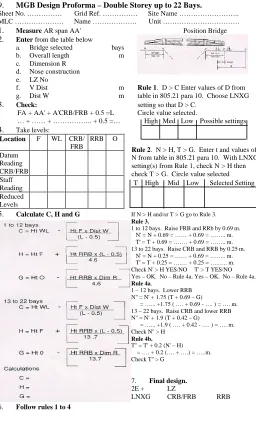
805.21 - MEDIUM GIRDER BRIGING (MGB) 1. MGB Ld Class, No of Bays and Length
SINGLE SPAN
Single Storey Double Storey Double Storey LRS (2)
SER MLC
Max length (m) No of bays
Max length (m) No of bays (1)
Max length (m) No of bays
(a) (b) (c) (d) (e) (f) (g) (h)
1 100(W) 9.8 5 27.4 10 31.1 12
2 70(T) 9.8 5 31.1 12 45.7 20
3 60(T) - - 32.9 13 -
-4 60 9.8 5 31.1 12 49.4 22
4 50 9.8 5 34.8 14 -
-5 40 13.4 7 38.4 16 -
-6 30 15.2 8 42.1 18 -
-7 24 17.1 9 45.7 20 -
-8 20 18.9 10 47.6 21 -
-9 16 22.6 12 49.4 22
NOTE: 1. For double storey brs the length of two ends of br (2e) must be added. 2. Data for LRS short post. For long post, only MLC 60.
Insert – Engineers
2. MGB Slope and Fatigue Data
SER CONFIGURATION MLC LENGTH CROSS SLOPE
(Unlded)
INITIAL FATIGUE LIFE
1 Single storey 60
70(T) 100(W) 9.8m 9.8m 9.8m 1:10 1:20 0 10,000 5,000 7,500
2 Double storey 60
60(T) 70(T) 100(W) 31.1m 32.9m 31.1m 27.4m 1:20 1:20 1:20 0 10,000 7,500 5,000 3,000 3 Double Storey Link
Reinforced Short Post
60 70(T) 70(T) 100(W) 49.9m 45.7m 49.9m 31.1m 1:20 1:20 0 0 10,000 10,000 5,000 4 Double Storey Two Span
With Span Junction
60 70(T) 100(W) 51.2m 51.2m 36.6m 1:20 1:20 0 10,000 3. Abbreviations
AR Angle of repose LRP Landing Roller Pedestal
A(A’) Loc of AR peg on far (home) bank LNH Launching Nose Heavy Baseline Line at grd level joining FRB and RRB and extended to F and O, or
the line at grd level joining RB and O and extended to F.
LNL Launching Nose Lt
BP Bottom Panel LNR Launching Nose Roller
8-48
BSB Bank Seat Beam LNXG Launching Nose Cross Girder
CRB Centre Roller Beam LR Launching Roller
DS Double Storey O Pt distance R from
RB/CRB/FRB
DU Deck Unit RB Roller Beam
E End of br RRB Rear Roller Beam
ETP End Taper Panel FRB Front Roller Beam F (F’) Loc of end of br pegs LRS Link Reinforcement Set 4. Summary of Distances
C Height of water below (neg) line joining banks (F-FRB) at a dist. W from FRB.
L LZ D Height of bottom of ETP above line joining banks (F-FRB)
at a distance W from FRB
R Max distance from RB/CRB/FRB to tail of br during const
G Height of grd at 0 relative to baseline T Height of Tail of br at 0 relative to baseline H Height of grd at F relate to baseline V Max dist. between FRB/CRB and LRP for DS brs
during de-launch when using a launching nose LZ Br Length (also F-F’) W Distance of Front of ETP from FRB at max
deflection 5. Dimensions of MGB components
a. Roadway width – 4.01 m b. One bay of br – 1.83 m long
c. End of br – 4.6 m long d. Ramp unit – 3.1 m long
Insert – Engineers