NONRESIDENT
TRAINING
COURSE
October 1997
Information Systems
Technician Training Series
Module 3—Network Communications
NAVEDTRA 14224
NOTICE
DISTRIBUTION STATEMENT A: Approved for public release; distribution is unlimited. Although the words “he,” “him,” and
PREFACE
By enrolling in this self-study course, you have demonstrated a desire to improve yourself and the Navy. Remember, however, this self-study course is only one part of the total Navy training program. Practical experience, schools, selected reading, and your desire to succeed are also necessary to successfully round out a fully meaningful training program.
COURSE OVERVIEW: In completing this nonresident training course, you will demonstrate a knowledge of the subject matter by correctly answering questions on the following subjects: Network Administration, LAN Hardware, and Network Troubleshooting.
THE COURSE: This self-study course is organized into subject matter areas, each containing learning objectives to help you determine what you should learn along with text and illustrations to help you understand the information. The subject matter reflects day-to-day requirements and experiences of personnel in the rating or skill area. It also reflects guidance provided by Enlisted Community Managers (ECMs) and other senior personnel, technical references, instructions, etc., and either the occupational or naval standards, which are listed in the Manual of Navy Enlisted Manpower Personnel Classifications and Occupational Standards, NAVPERS 18068.
THE QUESTIONS: The questions that appear in this course are designed to help you understand the material in the text.
VALUE: In completing this course, you will improve your military and professional knowledge. Importantly, it can also help you study for the Navy-wide advancement in rate examination. If you are studying and discover a reference in the text to another publication for further information, look it up.
1997 Edition Prepared by DPC(SW) Walter Shugar, Jr. and RMCS(SW/AW) Deborah Hearn.
Published by
NAVAL EDUCATION AND TRAINING PROFESSIONAL DEVELOPMENT
AND TECHNOLOGY CENTER
Sailor’s Creed
“
I am a United States Sailor.
I will support and defend the
Constitution of the United States of
America and I will obey the orders
of those appointed over me.
I represent the fighting spirit of the
Navy and those who have gone
before me to defend freedom and
democracy around the world.
I proudly serve my country’s Navy
combat team with honor, courage
and commitment.
CONTENTS
CHAPTER PAGE
1. Network Administration . . . .1-1 2. LAN Hardware . . . .2-1
3. Network Troubleshooting. . . 3-1
APPENDIX
I. Glossary . . . AI-1
II. Glossary of Acronyms and Abbreviations . . . AII-1 III. References Used to Develop the TRAMAN. . . AIII-1
INDEX . . . . . . INDEX-1
SUMMARY OF THE RADIOMAN
TRAINING SERIES
MODULE 1
Administration and Security—This module covers Radioman duties relating to administering AIS and communication systems. Procedures and guidance for handling of classified information, messages, COMSEC material and equipment, and AIS requirements are discussed.
MODULE 2
Computer Systems—This module covers computer hardware startup, including peripheral operations and system modification. Other topics discussed include computer center operations, media library functions, system operations, and troubleshooting techniques. Data file processes, memory requirements, and database management are also covered.
MODULE 3
Network Communications-This module covers network administration, LAN hardware, and newtwork trobleshooting. Related areas discussed are network configuration and operations, components and connections, and communication lines and nodes.
MODULE 4
Communications Hardware—This module covers various types of communications equipment, including satellites and antennas. Subjects discussed include hardware setup procedures, COMSEC equipment requirements, distress communications equipment, troubleshooting equipment, satellite theory, and antenna selection and positioning.
MODULE 5
CREDITS
Trademark Credits
ARCnet is a registered trademark of Datapoint Corporation.
Ethernet is a registered trademark of Xerox Corporation.
Novell is a registered trademark of Novell, Inc.
UNIX is a registered trademark of X/Open Company Ltd.
Windows 3.11 is a registered trademark of Microsoft Corporation.
Windows 95 is a registered trademark of Microsoft Corporation.
INSTRUCTIONS FOR TAKING THE COURSE
ASSIGNMENTS
The text pages that you are to study are listed at the beginning of each assignment. Study these pages carefully before attempting to answer the questions. Pay close attention to tables and illustrations and read the learning objectives. The learning objectives state what you should be able to do after studying the material. Answering the questions correctly helps you accomplish the objectives.
SELECTING YOUR ANSWERS
Read each question carefully, then select the BEST answer. You may refer freely to the text. The answers must be the result of your own work and decisions. You are prohibited from referring to or copying the answers of others and from giving answers to anyone else taking the course.
SUBMITTING YOUR ASSIGNMENTS
To have your assignments graded, you must be enrolled in the course with the Nonresident Training Course Administration Branch at the Naval Education and Training Professional Development and Technology Center (NETPDTC). Following enrollment, there are two ways of having your assignments graded: (1) use the Internet to submit your assignments as you complete them, or (2) send all the assignments at one time by mail to NETPDTC.
Grading on the Internet: Advantages to Internet grading are:
• you may submit your answers as soon as you complete an assignment, and
• you get your results faster; usually by the next working day (approximately 24 hours).
In addition to receiving grade results for each assignment, you will receive course completion confirmation once you have completed all the
assignments. To submit your assignment answers via the Internet, go to:
http://courses.cnet.navy.mil
Grading by Mail: When you submit answer sheets by mail, send all of your assignments at one time. Do NOT submit individual answer sheets for grading. Mail all of your assignments in an envelope, which you either provide yourself or obtain from your nearest Educational Services Officer (ESO). Submit answer sheets to:
COMMANDING OFFICER NETPDTC N331
6490 SAUFLEY FIELD ROAD PENSACOLA FL 32559-5000
Answer Sheets: All courses include one “scannable” answer sheet for each assignment. These answer sheets are preprinted with your SSN, name, assignment number, and course number. Explanations for completing the answer sheets are on the answer sheet.
Do not use answer sheet reproductions: Use only the original answer sheets that we provide—reproductions will not work with our scanning equipment and cannot be processed.
Follow the instructions for marking your answers on the answer sheet. Be sure that blocks 1, 2, and 3 are filled in correctly. This information is necessary for your course to be properly processed and for you to receive credit for your work.
COMPLETION TIME
PASS/FAIL ASSIGNMENT PROCEDURES
If your overall course score is 3.2 or higher, you will pass the course and will not be required to resubmit assignments. Once your assignments have been graded you will receive course completion confirmation.
If you receive less than a 3.2 on any assignment and your overall course score is below 3.2, you will be given the opportunity to resubmit failed assignments. You may resubmit failed assignments only once. Internet students will receive notification when they have failed an assignment--they may then resubmit failed assignments on the web site. Internet students may view and print results for failed assignments from the web site. Students who submit by mail will receive a failing result letter and a new answer sheet for resubmission of each failed assignment.
COMPLETION CONFIRMATION
After successfully completing this course, you will receive a letter of completion.
ERRATA
Errata are used to correct minor errors or delete obsolete information in a course. Errata may also be used to provide instructions to the student. If a course has an errata, it will be included as the first page(s) after the front cover. Errata for all courses can be accessed and viewed/downloaded at:
http://www.advancement.cnet.navy.mil
STUDENT FEEDBACK QUESTIONS
We value your suggestions, questions, and criticisms on our courses. If you would like to communicate with us regarding this course, we encourage you, if possible, to use e-mail. If you write or fax, please use a copy of the Student Comment form that follows this page.
For subject matter questions:
E-mail: [email protected] Phone: Comm: (850) 452-1501
DSN: 922-1501 FAX: (850) 452-1370 (Do not fax answer sheets.) Address: COMMANDING OFFICER
NETPDTC N311
6490 SAUFLEY FIELD ROAD PENSACOLA FL 32509-5237
For enrollment, shipping, grading, or completion letter questions
E-mail: [email protected] Phone: Toll Free: 877-264-8583
Comm: (850) 452-1511/1181/1859 DSN: 922-1511/1181/1859
FAX: (850) 452-1370 (Do not fax answer sheets.) Address: COMMANDING OFFICER
NETPDTC N331
6490 SAUFLEY FIELD ROAD PENSACOLA FL 32559-5000
NAVAL RESERVE RETIREMENT CREDIT
Student Comments
Course Title:
Information Systems Technician Training Series Module 3—Network Communications
NAVEDTRA: 14224 Date:
We need some information about you:
Rate/Rank and Name: SSN: Command/Unit
Street Address: City: State/FPO: Zip
Your comments, suggestions, etc.:
Privacy Act Statement: Under authority of Title 5, USC 301, information regarding your military status is requested in processing your comments and in preparing a reply. This information will not be divulged without written authorization to anyone other than those within DOD for official use in determining performance.
CHAPTER 1
NETWORK ADMINISTRATION
Upon completing this chapter, you should be able to do the following:
Describe how to establish communications with remote terminals and monitor system transmissions.
Describe how to start up, monitor, and terminate network processing.
Explain how to change network software configurations and how to analyze network hardware configurations.
Explain how to install and test software and how to perform system restorations.
Explain how to evaluate network requests.
Describe the procedures used to calculate network capacity.
Explain how to determine communications protocols and how to design a network.
Welcome to the wonderful world of networking. Networking has opened the world to connectivity. Networking gives an individual the capability to communicate and connect with another individual or another system in order to share resources.
The end result is to establish communications between two PC computers or two entirely different systems. The process used to reach that point can be done many ways. Once you have established connectivity and are communicating, then you will need to monitor the systems transmission to ensure the two computers are, in fact, communicating successfully. Some of the factors that will have to be taken into consideration are:
. What type of hardware will be needed
. What operating system (OS) will be used
. What applications will be needed
. What type of cabling will be used
NETWORK OPERATIONS
Networks consist of nodes that are interconnected by links. These nodes and links usually cover a
relatively small geographical area, commonly known as a local area network, ranging from a few feet to a mile. Nodes are the hardware, such as computers, terminals, hard disks, printers, and so on. Links are the communications media, such as twisted-pair wire, coaxial cable, or fiber optic cable that connects the nodes.
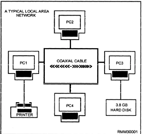
A network could be made up of 13 PCs, a server with a hard disk, 3 printers, and a plotter. Another network could be made up of 6 PCs (one of which is the network server) and a laser printer. Both are networks. When you connect individual PCs together (via cable), and each PC is allowed access to the other’s information and/or resources, you have created a network (see figure 1-1). By connecting PCs in this fashion, you are able to share all sorts of things. Examples are information in files; software, such as word processors, spreadsheet programs, and utilities; and peripheral devices, such as hard disks, printers, plotters, and fax machines.
A network gives you the capability of transferring data, files, programs, you name it, from one PC to another or even from one network to another. You can transfer a report or listing to any printer you desire on the network, provided you have access to the printer. How is that for flexibility? By connecting your PC into a network system, you can execute application programs stored on the server’s hard disk without having to worry about disk space or keeping track of diskettes. You can exchange files and programs with other users directly without copying them onto a diskette. Can you begin to see the power and flexibility built into a network system?
COMMUNICATIONS WITH REMOTE TERMINALS
[image:14.623.74.310.463.686.2]The ability to connect to the LAN through the use of remote terminals gives you great flexibility, whether it is being able to check your E-mail via a modem or check the status of the LAN by connecting to the network as a
Figure 1-1.—Connecting PCs to form a local area network.
remote console. The remote capabilities will increase productivity. The network supervisor can manage the system by establishing communications through a remote terminal.
Logins from Remote Locations
Remote access refers to logins from remote locations. These login procedures are accomplished by dialing into an access server (a special modem or computer) and logging in through this server.
The network modems that can be used as remote access servers must have a network interface card (NIC) compatible with the network to which the modem is providing access. Remote connections often require special timing considerations, because many network transactions must happen within a very limited time period.
Remote Console
A networking utility that enables a network supervisor to manage a server from a workstation or from a remote location using a modem. The supervisor can give commands and accomplish tasks just as if all the commands were being given directly at the server by simulating a direct connection to the server.
NETWORK STARTUP/SHUTDOWN
Keeping the system running is the most visible aspect of system administration. You’re the one they will call when the system has gone down (crashed). We will discuss the normal UNIX booting (startup) and shutdown processes. Shutting down and bringing up a UNIX system is actually very simple.
System Startup
Every time the system is booted, a series of steps must be performed before the system becomes available to users. Booting is the process of bringing a computer system up and making it ready to use.
The process begins when some instructions stored in ROM are executed which load the program boot from the boot partition into system memory. Boot loads the bootable operating system, which is also called the bootable kernel. The bootable kernel starts the init (initialization) program.
INIT.— One of the first things init does is check
configured, it is told what types of hardware devices to expect. Init will search for and attempt to initialize each physically attached device. Any device that does not initialize or that is missing will be marked as nonexistent and the driver disabled. Even if the device is later reconnected, it will be unusable until the system is rebooted.
When all is ready, the kernel verifies the integrity of the root filesystem and then mounts it. Init does the rest of the work that is needed in preparing the system for users. This includes mounting the remaining local disk partitions (those found in the file /etc/checklist); performing some filesystem cleanup operations (fsck); turning on the major UNIX subsystems, such as accounting and the print service; starting the network; mounting remote file systems; and enabling user logins.
SYSTEM MODES.— There are two primary
modes of system operation: single-user and multi-user. Single-user is a system state designed for administrative and maintenance activities which require complete and unshared control of the system. Single-user mode is sometimes called the maintenance mode. Single-user mode is entered via manual intervention during the boot process. Sometimes, however, the system will enter single-user mode if there are problems in the boot process that the system cannot handle on its own. Multi-user allows many users to all log onto the same CPU. Users can access different applications simultaneously or even the same application simultaneously. The kernel manages the different users by scheduling the use of the processing time as well as swapping programs and data in and out of memory through virtual memory to disk. The most important fact to remember is that the number of concurrent users depends on the amount of memory installed in the computer. Each user has a certain amount of memory set aside for his or her work, unless everyone is willing to tolerate slow response time from the network.
System Shutdown
While there are many occasions when shutting down or rebooting the system is appropriate, neither operation should be performed indiscriminantly. While it is generally not something to worry about, there is a degree of hardware fatigue associated with turning a computer system off and on again, and it is often better to let it run 24 hours a day than to shut it down at night.
REBOOTING.— There are only four common
situations in which rebooting the system is called for:
If you make changes to any of the system software or configuration files that are examined or executed only when the system is booted, you must reboot for these changes to take effect.
Some devices, especially printer and modem ports, can become confused enough that resetting them is only accomplished by re-initializing the system.
If the system has been up and running constantly for over a week, it is wise to bring the system down to single-user mode and run fsck. If any fixes are made to the root partition, the system must be rebooted.
If the system console becomes irretrievably hung, the system must be rebooted.
SHUTTING THE SYSTEM DOWN.— There are
two proper ways to shut down the operating system: shutdown and reboot. As a last resort, the system can be shut down by turning off the power to the CPU. This method is recommended only under emergency conditions because of its detrimental impact on system files and certain types of hard disk drives. These disk drives expect their floating heads to be parked prior to shutdown. Powering off the system could cause the heads to crash and cause irreparable damage to the disk.
Shutdown.— This command is the most often used
method of initiating a orderly system shutdown. It is the safest, most considerate, and most thorough to initiate a halt, reboot, or return to single-user mode. The command will send messages to each user’s terminal at progressively shorter intervals as the time for shutdown approaches. The messages tell the time of the shutdown.
Reboot.— This command terminates all currently
executing processes except those essential to the system, then halts or reboots the system. When invoked without arguments, reboot syncs all disks before rebooting the system. The command does not send a message out to the users, unless you use the message option.
MONITOR
l
l
l
To maintain a history of the performance of your system. Studying this history could point out potential failures long before they occur.
To provide a statistical basis for new equipment requests. Management is more likely to purchase new equipment if you can demonstrate that the current equipment will not meet the company’s needs.
To enable you to tune your network for optimum performance. This is especially true on larger networks with more than one file server. In some cases, you can provide a perceived increase in throughput by simply transferring tasks from one server to another.
Various network operating systems (NOSs) have their own utility programs to monitor what processing is taking place on their network. You can use these programs to monitor the status of your network, and some utilities give you the capability to monitor a particular job request.
REVIEW AUDIT LOGS
The main importance of reviewing audit/event logs is to monitor the security of the system. Besides, C2 Security compliance requires that the system be monitored (audited) continuously. Whether it pertains to the system – what hardware was accessed, security – identify who logged on (logged-in), or application – what software was accessed; usage must be tracked.
The term auditing refers to the process of recording events, such as file access, creations, deletions, the addition of print jobs, and so on, and using that information to detect usage violations or to confirm that network procedures are operating correctly.
A network administrator, by using the audit logs, can track what files were accessed, when they were accessed (date and time), by whom, and even what transactions were performed. Some logs even show you if the transaction was or was not successful with some type of message.
NETWORK CONFIGURATION
Equipment, the connections, and equipment settings for a network comprise the network configuration. The equipment refers to the hardware (computers, peripherals, boards, and cables), but may also include software under certain circumstances.
Because of equipment compatibility and interoperability, a system administrator needs to know considerable detail about all of the equipment that comprises the network. This information may include model numbers, memory specifications, enhancements, and so on. This information must be maintained, or conflicts between the equipment may occur. Most networking systems include a utility for recording system configuration information and updating it as the net work changes.
Record the current settings for each component as part of the configuration information. Avoid conflicts when deciding on specific settings. A conflict can arise because two boards want to use the same memory location or interrupt.
SYSTEM PARAMETERS
System parameters must be verified prior to installation and startup to avoid any conflicts. The majority of the conflicts involve system interrupts. An interrupt is a mechanism by which one computing element, such as a modem or a program, can get the attention of another elements. Interrupts may be generated by hardware or software.
Hardware Interrupt
There are 16 interrupt request lines (IRQs) for hardware interrupts in a PC environment. Each device attached to a computer can have an IRQ assigned. When the device wants service from the CPU, it signals on this line and waits.
IRQs have different priority levels, and the higher priority lines are assigned to the most important functions on the PC. By responding to IRQs according to their assigned priority, an operating system or interrupt handler can ensure that no vital activities are interrupted.
IRQ values for a device may be set through software or by manually setting them through the use of jumpers or DIP switches on the expansion board for the device. When configuring devices, it is important that you do not have two devices that use the same IRQ.
Software Interrupt
There are software interrupts for handling specific requests and for performing specific actions (for example, determining memory size). Interrupts can provide access to more functions (for example, DOS interrupt 2AH provides for network control functions).
SOFTWARE CONFIGURATIONS
All of the software that will be installed on the network will be configured for use on the system. Unfortunately, the manufacturers can’t configure the software to function properly on each and every system. It will be up to you to make configuration changes to get the optimum performance from the specific software that will be loaded on the network.
These changes can include one or more of the following: l l l l l Available memory
Type of peripheral (e.g., disk or tape drives, printers, etc.)
Number of users
Access speeds
Available disk space
Before making any changes to the software, ensure that there are adequate backups available to restore the system if problems are encountered. The most important thing to remember, when making changes, is to read the installation instructions that were supplied by the manufacturer first.
NETWORK PARAMETERS
If you think about the network, its performance is governed by both the hardware and software. The hardware has certain limitations that are set by the manufacturer and can’t be changed. You can’t speed up disk or memory access times, no matter what you do. The software, however, can be changed to help make the network run better.
Setting Parameters
Although the software is designed to run at the optimal rate, because each system is different there are some changes that can be made. Changes to these settings can allow the system to run even better, using all of its resources.
Some of these setting changes include:
Adjusting memory partitions
Drive/directory access
N u m b e r o f u s e r s
This is by no means a complete list of possible changes that can be made; refer to the operator’s manual for your specific software for changes that can be made.
Modifying Parameters
The modification of the network parameters on your specific system will depend on the software being used. Each manufacturer sets up the software to run at optimal performance. There will be times that the network’s performance falls off because of adding additional equipment, creating the need to change the parameters. When the parameters must be changed, always refer to the operator’s manual for the specifics.
A number of parameters can be changed to improve the network’s performance, including increasing the amount of memory used for disk sharing, print spooling, and printing. By increasing the buffer used for transferring files between the file server and workstations, the file server does not have to perform as many send operations and can perform other network procedures more quickly. By increasing the size of the buffer used for handling user requests, more user requests can be processed and the network can perform faster.
NETWORK PORT CONFIGURATION
A port is a connection on the back of the computer where you connect peripherals, switches, networks, or other devices. The port provides the electrical and physical interface between the device and the computer. There are two types of ports:
l
l
Parallel: A hardware connection used to send or
receive a lot of data over a short distance. These ports typically send eight bits of data simultaneously.
Serial: A hardware connection that is used to
send data one bit at a time and is very good for sending information over a long distance.
Port Address or Name
will have at least enough storage allocated to handle the data being written or read at the port.
A port name can be used instead of an address to refer to a port. A name is normally easier to remember than an address. Operating systems sometimes have predefine names associated with certain ports. For example, DOS reserves COM1 and LPT1 to refer to the first serial and parallel ports, respectively.
ANALYZE CONFIGURATION
Analyzing the configuration of the network can be accomplished in two different ways. The first and simplest way happens when the computer is turned on; the operating system goes out and checks the configuration. The second way is accomplished by using an application to test whether a remote device is properly connected to the system. The use of an application is the best way to analyze the configuration.
The application tests the remote device by sending out a signal to each device and waiting for the signal to return. This process is called “pinging.” The ping sent out is called an echo message, and the reply is called an echo reply message. The application sends out the echo message and, if the device is properly connected, it sends back an echo reply message. The receipt of this echo reply indicates that there is a viable connection. Some version of application software reports on how long it took to receive the echo reply and any lost replies. These reports provide information about the traffic and noise levels on the network.
SYSTEM RESOURCE LIMITS
The advantage of a network is it allows several people to share resources, both hardware and software. Hardware resources refer to printers, disk drives, CD-rom drives, scanners, and modems. Software resources include operating system, drivers, applications (word processing, database, etc.), management software, and data files. To avoid problems, such as slow response time and unavailability of resources, you must know the limits of the system resources.
Hardware Limits
The limitation involved with hardware is going to be waiting. A particular piece of peripheral equipment can be accessed by one user at a time. Only one job can be printed at a time, and only one user can be using a single modem at a time. This small inconvenience of access outweighs the cost of several different pieces of the same type (i.e., several printers or modems).
Software Limits
No matter which software package, whether application, mail, or operating system, there is a limited number of users that can use the software at one time. It is far cheaper to buy one multi-user package that allows for 25 users than to purchase 25 individual copies. But, it might run just a bit slower than an individual copy.
NETWORK SOFTWARE
Networks require the interaction of software and hardware. The system software to operate and control the network must be specifically designed for network operation. The application software/programs to solve user problems must also be specially designed to run on a network. Between the system software and the application software/programs, two pieces of software are needed. One is the telecommunications access software. It provides application programs access to the network so they can send and receive data. The other is the teleprocessing monitor, which is the interface between the telecommunications access software and the application programs. It handles the details of integrating these two. To install the system software, as with any software, follow the installation instructions supplied with the software.
SYSTEM SOFTWARE
It takes special system software to handle the unique and dynamic workloads of a network. This special software is called network system software. The network system software is sometimes referred to as the network operating system (NOS). It is different from the type of system software you normally use on your stand-alone PC. Network system software must be able to handle multiple users, multiple peripherals, network security, and be able to share information and application software, just to name a few differences. Normally, network system software runs on the network server. It includes such things as the network’s operating system software, communications software, and all the programs needed to manage the sharing of information and resources on the network. Without it, there would be no way to coordinate and manage the many components of a network into a functioning whole.
simultaneously. An example of multitasking is to have the network server transfer a message (using a program called E-mail) from one PC to another, save a 50-page document to hard disk, and send a report to a printer, in rapid succession. Only systems with multiple processors, such as a system with two 386 or 486 microprocessors, can process information simultaneously.
Network system software provides utility
programs, such as electronic mail (or e-mail). E-mail
gives network users the ability to send messages to one another over the network. If for some reason you needed to send a message to all the network users, E-mail is capable of sending your message to multiple users. Other utility programs sort, merge, and print files.
Network system software also provides data
protection. This includes data security/integrity and
backing up of files. Data security is a must if you are to limit access to sensitive and classified information. Data integrity prevents files from being updated by more than one user at a time. There are a number of ways you can control access to information on the network. One way is to divide the shared hard disk into several different sections, similar to making logical partitions. Once the different areas have been established, you can specify how the user can access them. Generally, the different levels of access can be designated for either private, shared, or public use. They are defined as follows:
. PRIVATE USE Only one user is allowed to access and make changes to the data in this area. For example, all of PO1 Smith’s work is located in the area \SMITH. Only PO1 Smith has access to this area, and only she can make changes.
. SHARED USE All users are allowed to access and make changes to the data in this area. For example, a shared area called \ADMIN could contain correspondence that can be updated by all the command’s Yeomen.
. PUBLIC USE All users are allowed to access this area; however, they cannot make any changes to the data. For example, the area called \DIRECTIV contains all command directives. You would want your users to be able to view the data but not be able to make any changes.
Security and data protection are provided by
identification and password security. When the users
log on the system, they must enter their correct
identification numbers along with their passwords (as a double check) to gain access to information. Another reason why data must be made secure is to prevent unintentional damage that can result when more than one user accesses and changes the same information at the same time. In a case such as this, neither user would know what the other had done, and the result would be corrupted data. To prevent this, network software often provides you with some type of locking capability. This locking feature prevents others from accessing the file or record when you are working on it.
To ensure a well-managed (network), the data must not only be secure, it must also be backed upon a regular basis. Files must be backed up if all the information on the network server’s hard disk is to be saved in the event of a hard disk failure, a sudden power surge, or loss of power. Tape backup systems are very effective in that not only the tapes but also the tape units themselves can be stored off-site, which provides for additional security.
APPLICATION SOFTWARE
In addition to network system software, users of (network) require application software to carry out their specific requirements. You are familiar with many of the application software functions/packages available. They include word processing programs, database management programs, spreadsheet programs, computer aided design (CAD) programs, tutorials, and so on. Application software shared on a network is different from the software you use on your individual or stand-alone PC. It is specially designed to work on a network—to handle the demands of many users and to share resources while serving many users. It can also provide data security features, such as file or record locking and password recognition. Because network versions of application software are designed to be used by many users, a network software license agreement often costs more than a standard license.
Before leaving this section, you need to know a few other things about network software. Network system software features often vary from one network system to another. The system software can also dictate what hardware components CAN and CANNOT be used, and how the network CAN or CANNOT be configured.
SOFTWARE INSTALLATION
software. You will normally find this information on the side of the box and sometimes even on the back of the box the software comes in. The following requirements and recommendations will normally be listed:
Any other system/hardware requirements that may be needed will also be listed. As an example, these requirements might include: one CD-ROM drive; microphone, for voice annotation feature; a mouse or compatible pointing device; 2400 or higher baud modem (9600 baud modem recommended); headphones or speakers; and type of messaging software required to use e-mail; etc.
Once you have determined all of the above information, you will need to determine whether it will be run on a network as shared. Before you install the software, you need to read the installation instructions that come with the software application in their entirety. It is strongly suggested that you read a file normally called the “READ. ME” file, because that is where you will find the most up-to-date information (changes) that have been made to the application.
SOFTWARE TESTING
Once the software is installed on the network, it must be tested. The reason for the testing is to make sure that all aspects of the program work. There are two avenues for testing the software: an independent testing company, and end-users.
The advantage of an independent testing company is that it will use a more comprehensive and systematic testing method. Testing aimed at the generic network user is the disadvantage of the testing company.
Using end-users has both advantages and disadvantages when it comes to testing the software. An advantage is that the end-users will test all facets of the software. A disadvantage is the haphazard methods of most end-users when it comes to testing the software.
SYSTEM RESTORATION
The network is the most error-prone of the system components. Usually, multiple vendors are involved, and too few qualified personnel are available to support all the implemented networks. Due to these inherent problems with the network, system degradation is a part of operation, and getting the system back into normal operation is of great importance.
Three primary methods are used to provide service restoration after system degradation. They are as follows:
l Redundancy. Redundancy refers to duplicate hardware and network facility segments that are available at all times. If the primary path fails, a secondary path can continue network operation.
l Rerouting. Rerouting is the transmission of information along alternative paths. The end-to-end transmission initially required is still obtained.
l Reconfiguration. Reconfiguration is the manual or automatic reconfiguration of equipment and/or lines to achieve the original end-to-end connections. Reconfiguration may be the most costly method in time because it requires knowledgeable personnel and the appropriate switching of equipment.
NETWORK DESIGN
The first step in designing a network is to decide whether or not a network is needed. This decision is made easier by soliciting network requests from the command. Once the decision is made to design and install a network, you need to look at the capacity and reliability of the network and the design options.
Many design options are available for designing and building a LAN. Four interrelated factors contribute to this great flexibility. They are physical layout (topology), access method (protocol), physical connection (cabling), and networking operating system (NOS). There is one additional factor to be considered when designing a network, the need for security. This need for security is met by the implementation of a firewall.
NETWORK REQUESTS
Before committing the money to install a network, you need to research the need for a network for the command. The best way to conduct this research is by using a network request. Always make sure you have all the available information to guide your planning. The following are some guidelines to use when beginning to plan for a network:
Calculate your needs as completely as possible. This will help you decide what components and services will need to be included in the network.
Determine what resources are available at your command for planning, implementing, and running a network.
Determine who needs access to the network and where these people are located. This information will help determine whether a network is a necessary or feasible solution for the command’s needs. It will also provide information regarding cabling requirements.
Get to know the current usage and needs in detail. This information will also help decide whether a network is the best solution.
Get a detailed drawing of office locations, existing wiring, and possible server locations. After gathering and evaluating the information, the decision can be made as to whether or not a network is the way to go. If it is decided to go with a network, it is time to determine what resources are available.
CALCULATING NETWORK CAPACITY
After you’ve determined the available resources, use only a portion of these for your working calculations. This downsizing will protect you against the losses of these resources.
The amount by which you should decrease your estimates depends on the possible costs if your network is a failure and on how stable the resources are. A general rule to follow is to assume that your available resources will be anywhere from 10 to 50 percent less than estimated. Let’s say, that you have 25 PC workstations available to connect to the network. You should plan on connecting 22 (12% less than available), which would leave you with 3 spare workstations. Another example would be: if your NOS is capable of having 250 accounts, reducing this quanity by 10% (25) will help reduce the time that the users will be waiting for the network to respond to their request.
The opposite of this rule is applied when it comes to the cost calculations. When you decide how much time and money it is going to cost, it is a good idea to add an amount or a percentage to the calculations. Projects like networks never seem to be completed on time or at cost, due to unforeseen circumstances.
LAN CONFIGURATIONS (TOPOLOGIES)
The physical arrangement of a LAN’s components is called its configuration or topology. The three major types of LAN configurations, or topologies, are the
star, the bus, and the ring. You can also create hybrid
topologies by combining features of these configurations. For example, several bus networks can be joined together to form a ring of buses.
Each topology requires LAN components to be connected in a different arrangement. These components are also referred to as nodes. Remember, a node is any point on a network where data can be sent (transmitted) or received—a workstation, server, and so on.
The Star Network
shown in figure 1-2. Only one cable is required from the central computer to each PC’s network interface card to tie that workstation to the LAN. The star is one of the earliest types of network topologies. It uses the same approach to sending and receiving messages as our phone system. Just as a telephone call from one person to another is handled by a central switching station, all messages must go through the central computer or network server that controls the flow of data. You can easily add new workstations to the network without interrupting other nodes. This is one of the advantages of the star topology.
Another advantage of star topology is that the network administrator can give selected nodes a higher priority status than others. The central computer looks for signals from these higher priority workstations before recognizing other nodes. Also, the star topology permits centralized diagnostics (troubleshooting) of all functions. It can do this because all messages must first go through the central computer. This can prove invaluable for ensuring network security has not been breached. So much for the good news; now for the bad news, or the disadvantages of the star network. Of all the topologies, the star is the least reliable because it has a single point of failure. The network relies mainly on the central computer for all functions. If it fails, all nodes also stop functioning, resulting in failure of the entire network. This is precisely the same weakness multi-user computer systems have that rely on a central processor.
The Bus Network
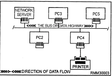
[image:22.616.78.299.487.699.2]The bus topology is like a data highway. That is, all components or nodes are connected to the same cable,
Figure 1-2.—A star network topology.
and the far ends of this cable never meet (see figure 1-3). Bus LANs are best suited to applications involving relatively low usage of the bus coupled with the need to pass relatively short messages from one node to another. In many such networks, the workstations check whether a message is coming down the highway before sending their messages. Since all nodes share the bus, all messages must pass through the other workstations on the way to their destinations. Each node checks the address attached to the message to see if it matches its own address. Bus topologies allow individual nodes to be out of service or to be moved to new locations without disrupting service to the remaining nodes.
Unlike the star topology, where dozens of cables come together at the central computer causing logistical problems, bus cabling is simple. The bus topology is very reliable, because if any node on the bus network fails, the bus itself is NOT affected, and the remaining nodes can continue to operate without interruption. Many of the low-cost LANs use a bus topology and twisted-pair wire cabling.
A disadvantage of the bus topology is that generally there must be a minimum distance between workstations to avoid signal interference. Another disadvantage is that nodes must contend with each other for the use of the bus. Simultaneous transmissions by more than one node are NOT permitted. This problem, however, can be solved by using one of several types of systems designed to control access to the bus. They are collision detection, collision avoidance, and token passing, which we will discuss shortly. Also, there is no easy way for the network administrator to run diagnostics on the entire network. Finally, the bus network can be easily compromised by an unauthorized network user, since all messages are sent along a common data highway. For this reason, it is difficult to maintain network security.
[image:22.616.336.574.536.698.2]Figure 1-4.—A ring network topology.
The Ring Network
In a ring network, all of the components or nodes are connected to the main cable, and the cable forms a ring, as shown in figure 1-4. This topology allows a node to send a message to another node on the ring. However, the message must be transmitted through each node until it reaches its destination. Messages proceed from node to node in one direction only. Should anode fail on the network, data can no longer be passed around the ring unless the failed node is either physically or electronically bypassed. Using bypass software, the network can withstand the failure of a
workstation by bypassing it and still be able to maintain the network’s integrity. One of the major issues in a ring topology is the need for ensuring all workstations have equal access to the network.
One of the major disadvantages of ring topologies is the extreme difficulty of adding new workstations while the network is in operation. Normally, the entire network has to be brought down while a new node is added and cabling reattached. However, this particular problem can be overcome by initially setting up the network with additional connectors. These connectors enable you to add or remove nodes while the network remains intact and in operation. The addition of the connectors is accomplished with the addition of a multistation access unit (MAU). The MAU is a wiring concentrator which allows workstations to be either inserted or bypassed on the ring.
The Distributed Star (Tree) Network
The distributed star or tree topology (figure 1 -5) can provide many of the advantages of the bus and the star topologies. It connects workstations to a central point, called a hub. This hub can support several workstations or hubs which, in turn, can support other workstations. Distributed star topologies can be easily adapted to the physical arrangement of the facility site. If the site has a high concentration of workstations in a given area, the system can be configured to more closely resemble a
[image:23.615.64.523.439.706.2]star topology. If the workstations are widely dispersed, the system can use inexpensive hubs with long runs of shared cable between hubs, similar to the bus topology.
PROTOCOLS
Network protocols are an important component; they define how networks establish communications between elements, exchange information, and terminate communications. Protocols have two major operational functions. They establish the circuit for transmission (handshaking) and for the transmission itself. Transmission is conducted subject to the line dicipline. The line discipline is the sequence of operations that actually transmits and receives the data, handles the error-control procedures, handles the sequencing of message blocks, and provides for validation for information received correctly.
Two representative protocols, which control line d i c i p l i n e , a r e : t h e B i n a r y S y n c h r o n o u s Communications Protocol (Bisync) and the Synchronous Data Link Control (SDLC).
and protocol. The principal access methods are contention and token passing.
Contention
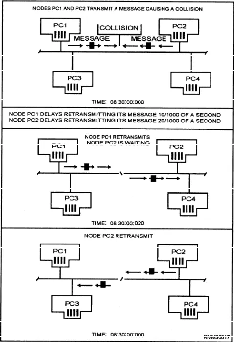
The contention method features Carrier Sense Multiple Access (CSMA) and Carrier Sense Multiple Access with Collision Detection (CSMA/CD). (See figure 1-6.) Access for both is on “a come, first-served basis. The CSMA scheme is very similar to a citizens band (CB) radio. Stations with data to send listen to the channel and wait until it is clear to transmit. With CSMA/CD, if two or more workstations transmit simultaneously, their messages will collide. As soon as a workstation detects a collision, it ceases transmission, monitors the network until it hears no other traffic, and then retransmits. Most contention networks assign a unique retry algorithm to vary the wait-and-retry period. This algorithm reduces the likelihood that after a collision, two workstations will transmit retries simultaneously.
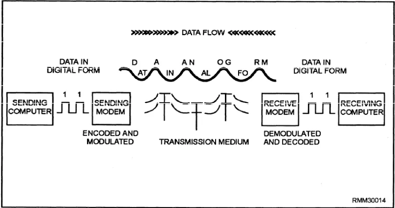
l Bisync is a half-duplex protocol that transmits strings of characters at lower speeds over dial-up circuits. Information movement is one direction at a time, with each data transfer being answered by an acknowledgement.
l SDLC is a control procedure that sends multiple blocks of data and returns a single acknowledgement for many blocks, thereby increasing the amount of time spent transmitting data. The bits that are put before and after the message at the transmitting end are removed at the receiving end, so only the message is presented to the user.
The hardware chosen for the network plays apart in the choice of network protocol. Most users and many of the vendors that build clone-type equipment would like to see universal interfaces. Others feel that the availability of different specifications will lead to a proprietary set of equipment, even though they favor the overall IS0 specifications (which are covered later in this chapter).
ACCESS METHODS
[image:24.615.333.572.345.694.2]Another decision to be made is which access method to use. Access methods are the arrangements used to ensure that each workstation has fair and equal access to the network. The access method that will be used is governed primarily by the network’s topology
Token Passing
Token passing is an orderly access method (figure 1-7). Each workstation passes on the opportunity to transmit to its closest neighbor, until a station is found with a message to send. This permission to transmit is called a token. When a workstation with data to send is handed a token, part of the token is changed, indicating it is carrying a message, and then data is transmitted with the token. The token is then passed around the network, and every station checks to see if the message is intended for them. The receiving station copies the message from the token but then passes the unchanged token along the network. When the transmitting station receives the same token, it knows the message has been passed around the network. The transmitting station erases the message and puts the empty token back into circulation on the network. The amount of information that may be transmitted during possession of the token is limited so that all workstations can share the cable equally.
Network Standards
[image:25.614.310.546.504.688.2]These access methods (CSMA/CD, CSMA/CA, and token passing) with their transmission medium (twisted-pair wire, coaxial cable, or fiber optic cable), are just one of several aspects (or levels) of an entire LAN structure. The topologies and network access methods just presented only establish a way to connect workstations or nodes together and how to pass along packets of data. These packets of data may be programs, data, system or personal messages, and so on. Above this hardware/software level are a number of other levels that are just as important in a LAN’s design. These are the levels that define how the LAN system manages its resources, how a user like yourself is able to log onto another node’s hard disk, how a common laser
Figure 1-7.—A ring network using the token passing access method.
printer is used by all nodes, how one file is passed among many users, and so on. If order and discipline are to be maintained on the network, standards or protocols must be established and adhered to. This allows the LAN to function in an efficient and effective manner.
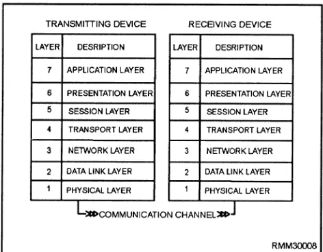
Over the past few years, a number of network standards or protocols have been developed by the International Standards Organization (ISO). They provide some level of uniformity among computer manufacturers and network vendors. ISO is one of several governing organizations in this field that has developed a series of protocols (rules to live by) to ensure compatibility for the many different vendors who design network hardware and software products. IS0 has defined a seven-layer architecture. These seven layers of standards, shown in figure 1-8, define a generalized architecture called the Reference Model of
open Systems Interconnection. It is also known as
the OSI reference model or OSI model. The primary purpose of the OSI model is to provide a basis for coordinating the development of standards that relate to the flexible interconnection of incompatible systems using data communications facilities.
The OSI model does NOT define any one vendor’s particular network software as such, nor does it define detailed standards for any given software. It simply defines the broad categories of functions that each of the seven layers should perform. The OSI model can include different sets of standards at each layer that are appropriate for given situations. For example, in a very simple data communications system, one that uses a simple point-to-point link, the software at the
[image:25.614.46.278.543.717.2]level layers (say 5, 6, and 7) might be very simple or possibly nonexistent. However, in a very complex data communications system, all seven software layers may be implemented. Although there is no requirement for any hardware or software vendor to adhere to the principles set forth in the OSI model, there is a worldwide trend in the computer industry toward acceptance and conformance to these standards.
About now, you may be asking yourself, what are these seven software layers (shown in figure 1-8), and why all the need for protocols? Don’t all computers work in binary? Do they not all have operating systems? If a computer wants to communicate with another system, do you not simply connect them together using some type of cable? The answers to these questions are yes, yes, and yes; however, the commonalities seem to stop there.
Ideally, if the hardware, network software, application software, and cabling were all supplied by the same manufacturer, we would have relatively few problems to contend with when we design and implement a network. Everything would work together rather smoothly. However, a computer manufacturer’s architecture can make it difficult to interconnect h a r d w a r e o f f e r e d b y o t h e r c o m p e t i n g manufacturers/vendors. The protocols used by communications devices are also highly complex and are often completely different from one manufacturer to another. Then, there is the network software. Network software from one LAN vendor usually won’t work on a competitor’s network, nor will the application programs. Even the cabling must be selected for a specific local-area network.
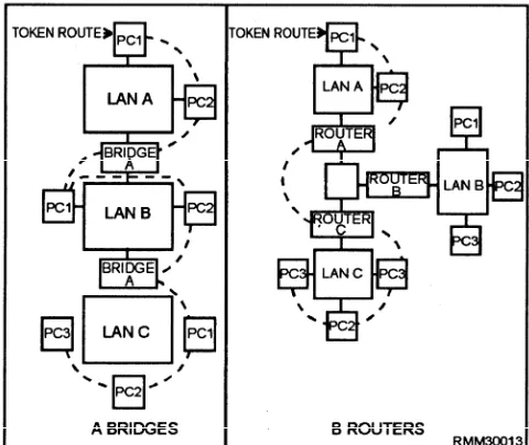
We could go on and on explaining the many incompatibilities that exist within these different areas, but the good news is that many hardware and software manufacturers/vendors provide interfaces. These various types of interfaces (bridges, gateways, routers, and so on) allow networks to be compatible with one another. At this point, we briefly talk about the seven software layers defined in the OSI model to give you some idea of what they are and why they are needed. To illustrate how the OSI model works, we are using the analogy of sending a letter using the U.S. postal system.
Layer l—The physical layer is concerned with
the transmission of the unstructured raw bit stream over a physical meduim. It addresses the electrical, mechanical, and functional interface to the carrier. It is the physical layer that carries the signals for all the higher layers, as follows:
Voltages and pulse encoding of bits
Media and media interface (cables, connectors, NIC, and so on)
Line discipline (full- or half-duplex)
Pin assignments
In our mail analogy, the mail truck and the highway provide the services of the physical layer.
Layer 2—The data link layer provides error-free
transmission of information over the physical medium. This allows the next higher layer to assume virtually error-free transmission over the link. The data link layer is responsible for getting data packaged and onto the network cable. It manages the flow of the data bit stream into and out of each network node, as follows:
. Creates and recognizes frame boundaries
l Checks received messages for integrity
. Manages channel access and flow control
. Ensures correct sequence of transmitted data The data link layer detects, and when possible, corrects errors that occur in the physical layer without using the functions of the upper layers. It also provides flow-control techniques to ensure link-buffer capacity is not exceeded. In our analogy, the data link layer is concerned with sending the mail trucks onto the highway and making sure they arrive safely.
Layer 3—The network layer decides which
physical pathway the data should take, based on network conditions, priorities of service, and other factors. Software on the network interface card must build the data packet so the network layer can recognize and route the data to the correct destination address. It relieves the upper layers of the need to know anything about the data transmission and switching technologies used to connect the systems. It is responsible for establishing, maintaining, and terminating connections across the intervening communications facility, as follows:
Addresses messages
Sets up the path between communicating nodes on possibly different networks
Routes messages among networks
*
l
l
Controls congestion if too many packets are on the network
Translates logical addresses or names into physical addresses
Has accounting functions to count packets orbits sent by users to produce billing information This layer acts in our postal service analogy, like the regional mail distribution centers throughout the country. The trucks are directed to the centers and are routed along the best path to their final destinations.
Layer 4—The transport layer ensures data units
are delivered error-free, in sequence, with no losses or duplications. It relieves higher layer protocols from any concern with the transportation of data between them, as follows: l l l l l
Message segmentation—accepts data from the session layer, splits it up into smaller units, and passes the units down to the network layer
Establishes and deletes host-to-host connections across the network
Multiplexes several message streams onto one channel and keeps track of which message belongs to which connection
Provides reliable end-to-end delivery with acknowledgment
Provides end-to-end flow control and window management
The transport layer functions are provided by the mail truck dispatcher, who takes over if there is a wreck out in the system. If the network goes down, the transport layer software will look for alternate routes or perhaps save the transmitted data until the network connection is reestablished.
Layer 5—The session layer allows users on
different machines to establish sessions between them. It performs the functions that enable two applications to communicate across the network, performing security, name recognition, logging, administration, and other similar functions. Unlike the network layer, this layer is dealing with the programs in each machine to establish conversations between them, as follows:
Allows two applications processes on different machines to establish, use, and terminate a connection (or session)
Performs synchronization between end-user tasks by placing checkpoints in the data stream so if the network fails, only the data after the last checkpoint has to be retransmitted
Provides dialogue control (who speaks, when, how long, and so on)
The session layer in our postal agency recognizes different zip codes and reroutes letters.
Layer 6—The presentation layer formats data to
be presented to the application layer. It can be viewed as the translator for the network. This layer provides a common representation for data that can be used between the application processes. The presentation layer relieves the applications from being concerned with data representation, providing syntax independence, as follows:
l
l
l
Encodes data in a standard way (integers, floating point, ASCII, and so on)
Provides data compression to reduce the number of bits that have to be transmitted
Provides data encryption for privacy and authentication
This layer functions like a translator who translates a letter from French into English.
Layer 7—The application layer serves as the
window for the application process to access the OSI environment. This layer represents the services that directly support users and application tasks. It contains a variety of commonly needed protocols for the following:
Network virtual terminals
File transfers
Remote file access
Electronic mail
Network management
In our analogy, the application layer is the person who writes or reads the letter.
CABLING
would be fewer hassles when it came time to figure out such things as line speeds, line capacities, variations in line distortion, and so on. However, there area number of types, ranging in cost and capabilities. In the following paragraphs, we examine the advantages and disadvantages of twisted-wire pairs, baseband and broadband coaxial cabling, and fiber optic cabling.
Twisted-wire Pairs
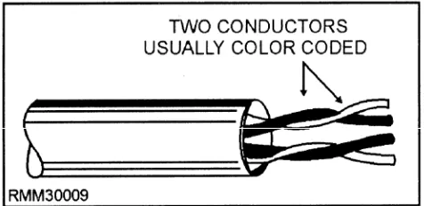
Twisted-wire pairs, also known as twisted-pair wire or cable, is by far the least expensive transmission media. It consists of two insulated wires twisted around each other so that each wire faces the same amount of interference (noise) from the environment (see fig. 1-9). Unfortunately, this noise becomes part of the signal being transmitted. Twisting the wires together reduces but does not eliminate the noise.
Twisted-pair wire comes in a wide range of gauges and pairs. Wire has an American Wire Gauge (AWG) number based on its diameter. For network purposes, 22- and 24-gauge wires are the two most common types of twisted-pair media. Some local-area networks use the same inexpensive, unshielded twisted-pair cables telephone companies use. Others require a higher data grade quality. It’s not uncommon to have several hundred pairs (and, in some cases, thousands) of wires placed in a single cable. Normally, each twisted-wire pair in a cable can accommodate a single phone call between two people or between hardware devices.
[image:28.613.66.304.589.705.2]The advantages of using telephone wires are their relative low cost and their availability. Their disadvantages include susceptibility to signal distortion errors and the relatively low transmission rates they provide over long distances. Twisted wire can handle a data flow of up to approximately one megabit per second (Mbps) over several hundred feet. For a small local-area network with a limited number of users, twisted-pair is an ideal choice because it is both inexpensive and easy to install. A phenomenon called
Figure 1-9.—Twisted-wire pairs (2 wire pairs shown).
crosstalk exists in twisted-wire pairs whenever
transmission occurs at a high rate of speed. Crosstalk is taking place whenever you can hear someone else’s conversation in the background; say Mr. Frost telling Mrs. Christmas what a great recipe he has for southern fried chicken, or Mrs. Brush telling Mr. Smith what a large fish she caught in the Gulf of Mexico, while you’re trying to carry on a conversation with your party. With voice communications this really isn’t a problem; however, crosstalk can inhibit the high-speed transmission required for data communications.
Twisted-wire pairs used in data communications are either private or public lines. Private lines are those provided by the user. Public lines are those provided by a common carrier such as American Telephone and Telegraph (AT&T). Generally, public lines are used whenever distances are great or the terrain or other environmental factors prohibit the use of private lines. Public lines may be either switched lines or leased lines.
Switched lines are used whenever the amount of
data to be transmitted is short in duration or when many locations must be contacted for relatively short periods of time. There is a drawback. The telephone company cannot guarantee you exactly which path or switching equipment such a connection will use. Therefore, the speed and quality of the switched connection are questionable.
Leased lines come into play when the connection
time between locations A and B is long enough to cover the cost of leasing, or if higher speeds than those available with switched lines must be attained. Leased lines can also be conditioned by the telephone company to lower the error rate and increase transmission speeds. Conditioned leased lines typically operate at speeds of up to 64,000 bits per second (bps). Very-high-speed connections are also available from the common carrier. These are designated T1, T2, T3, and T4, and offer transmission rates of 1.5, 6.3, 46, and 281 million bits per second (Mbps), respectively.
Coaxial Cables
Coaxial (or coax) cable, the medium used by most cable television companies, was developed primarily because of the crosstalk in twisted-wire pairs when transmission occurs at a high rate of speed. While coax is more expensive than twisted-pair, it can transmit data significantly faster, over much longer distances, and with less electrical interference.
an insulating layer, a shielding layer, and a weather proof outer jacket, as shown in figure 1-10. It is almost as easy to install as twisted-pair, and is the preferred medium for many of the major local-area networks. Coaxial cable is used extensively in local-area networks whenever the distance involved is relatively short, generally less than 2 miles for baseband LANs and 10 miles for broadband LANs. It is used in both baseband and broadband networks. Wait a minute! You say you want to know what the terms baseband and broadband mean and how they relate to networks? Not to worry; we explain them to you a little later in the text, but for now, all you need to know is that they both deal with the way data is transmitted (in the form of electrical signals) through some type of medium.
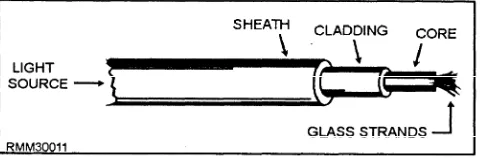
Fiber Optic Cable
[image:29.619.309.549.48.127.2]Fiber optic cable is to coaxial cable is to twisted-pair as the F-18 Hornet is to the Corvette is to the model T. It is the newest of the communication mediums, one that was spurred by the development of laser technology. Fiber optic cable (shown in fig. 1-11) consists of thousands of clear glass fiber strands, each approximately the thickness of a human hair. Transmission is made possible by the transformation of digital data into modulated light beams, which are sent through the cable by a laser light-emitting diode (LED) type device at incredibly fast speeds. Transmission rates available (as of 1990) range up to approximately 1 billion (or giga) bits per second (Gbps), with speeds over 2 Gbps possible. When thinking in terms of frequencies, light frequencies are extremely high. They are approximately 600,000 times that of the highest television channel. In terms of data communications, the higher the frequency of the signal, the more information it can carry. Put simply, every hairlike fiber within a fiberoptic cable has the capacity to carry many hundreds of local-area network channels simultaneously. When dealing with fiber optic cable, you will hear such terms as:
Figure 1-10.—Coaxial cable,
l
l
[image:29.619.43.283.571.709.2]*
Figure 1-11.—Fiber optic cable.
Monomode— Single fiber cable
Multimode— Several fibers within a cable
Graded index— A variation of multimode
Some of the major advantages of fiber optics over wire media include speed, size, weight, longevity, and resistance to tapping without being noticed. Since it carries no electrical current, it is immune to electrical interference of any kind, and there is no worry of it being a shock hazard.
One big disadvantage of fiber optic is the tighter restrictions on how much the cable can be bent. Other disadvantages include higher cost, and the inability to add on new workstations while other stations are active. Although it is relatively easy to splice the fiber optic cable and add new stations, the network or a portion of the network must be down while preparing the splice. On the other hand, if your activity has serious interference problems, or has a need for absolute network security, or the need to send signals several miles, then fiber optics might be the only solution.
Cable Selection