CORBA based Middleware for Cooperating
Mobile Robots
Colin Ryan B.Tech.
September 2000
A Dissertation submitted in partial fulfilment of the requirements for the Degree of M.Sc. in Computer Science
Declaration
I, the undersigned, declare that this dissertation is entirely my own work, except where otherwise accredited, and that it has not been previously submitted for a degree at this or any other university or institution.
_____________________
Colin Ryan
Permission to Lend and/or Copy
I hereby declare that Trinity College may lend or copy this dissertation upon request.
_____________________
Colin Ryan
Abstract
An embedded system is an autonomous information processing system that
determines or controls to a large extent the behaviour of a larger system. The
proliferation of embedded systems applications is increasing daily, yet most
implementations are largely proprietary and utilise very few existing software
standards in implementing their external interfaces. For a particular class of
embedded system, those in use in mobile environments, the use of wireless
communications protocols is a fundamental requirement.
The aim of this research is to investigate the applicability of the Object
Management Group’s Common Object Request Broker Architecture (CORBA)
to designing and implementing middleware (ORBs) to present interfaces to
embedded systems. The CORBA standard enables the construction of distributed systems of multiple components with complex interactions and
hence supports the building of distributed architectures modelling real-world
systems. The project also uses a wireless protocol to assess the suitability of
CORBA to embedded systems that operate in mobile environments. The
applicability of the CORBA standard is assessed with a canonical application
utilising the Lego Mindstorms Robotics kit.
Having designed and built the test system outlined above, the suitability of the
utilised technologies to the project environment, and hence to that of
embedded systems in mobile environments, is assessed. Conclusions are
drawn as to system performance and robustness as well as exploration of
Acknowledgements
I would like to thank my supervisor, Dr. Vinny Cahill, for all his help and guidance through the year. Thanks to Jim, Andy and Ray of the DSG group for their assistance at various stages of this work and all my classmates for a great year and barrel of laughs (and several of beer).
Table Of Contents
1 INTRODUCTION ...1
1.1 Embedded Systems ... 1
1.2 Mobile Devices ... 2
1.3 Common Object Request Broker Architecture (CORBA) ... 3
1.4 Applying CORBA to Embedded Systems ... 4
1.5 Project Objective ... 6
1.6 Design Overview ... 7
1.7 Project Achievements ... 8
1.8 Roadmap ... 9
2 BACKGROUND ...11
2.1 Embedded Systems ... 11
2.1.1 Overview ... 11
2.1.2 Engineering Constraints ... 13
2.1.3 Embedded Systems in Distributed Environments ... 13
2.2 The Common Object Request Broker Architecture (CORBA) ... 15
2.2.1 Overview ... 15
2.2.2 The CORBA ORB ... 16
2.2.3 Interface Definition Language... 17
2.2.4 CORBA Services ... 18
2.3 The General Inter-ORB Protocol... 19
2.3.1 Overview ... 19
2.3.3 The GIOP Message Set ... 23
2.3.4 Transport Assumptions... 30
2.4 Object References ... 31
2.5 CORBA and Embedded Systems ... 33
2.5.1 Overview ... 33
2.5.2 Embedded CORBA Research... 35
2.6 The Lego Mind Storms Robotics Invention System... 37
2.6.1 Overview ... 37
2.6.2 The RCX Brick ... 38
2.6.3 The Development Process and Tools ... 39
2.6.4 LegOS and the Layered Network Protocol... 40
2.7 Mobile Applications... 42
2.7.1 Overview ... 42
2.7.2 Communications Characteristics ... 42
3 DESIGN...45
3.1 Overview... 45
3.2 The Data Representation Syntax... 47
3.3 The ORB Message Set ... 48
3.3.1 Client Initiated Messages ... 48
3.3.2 Server Initiated Messages... 50
3.3.3 Common Messages... 51
3.4 The ORB Transport Protocol ... 52
3.5 Communication End-Points ... 53
3.6 An Object Addressing Format ... 53
3.7 The IIOP to ESIOP Bridge ... 57
3.8 The Environment Specific ORB on the RCX (nanOrb) ... 59
4 IMPLEMENTATION...63
4.1 Implementation Goals ... 63
4.2 The Application and its IDL specification... 64
4.3 The Client Implementation... 65
4.4 The Gateway Implementation ... 66
4.5 The nanOrb ESIOP implementation ... 69
4.6 The RCX ORB implementation - nanOrb ... 69
4.7 Difficulties Encountered ... 72
5 EVALUATION ...74
5.1 Overview... 74
5.2 Efficiency ... 75
5.4 Architecture Comparison ... 78
5.5 Improving the nanOrb Architecture ... 80
6 CONCLUSION...81
6.1 Work Completed ... 81
6.2 Work Remaining ... 82
6.3 Further Research... 82
Table of Figures
Figure 1 The Target Architecture ...7
Figure 2 The Object Management Architecture ...15
Figure 3 Object Request Being Sent Through the ORB...17
Figure 4 GIOP Defined Primitive Data Types...21
Figure 5 Octet Sizes of Primitive Data Types...22
Figure 6 The 1.1 GIOP Messages ...23
Figure 7 The GIOP Protocol Header IDL ...24
Figure 8 The GIOP 1.1 Request Header IDL ...25
Figure 9 The GIOP 1.1 Request Header IDL ...26
Figure 10 The GIOP Cancel Request Header IDL ...27
Figure 11 The GIOP Locate Request Header IDL ...28
Figure 12 The GIOP Locate Reply Header IDL...29
Figure 13 The Interoperable Object Reference IDL ...32
Figure 14 The structure of LNP packets...41
Figure 15 The nanOrb IOR Profile ID...56
Figure 16 The IIOP to ESIOP Half-Bridge...58
Figure 17 The nanOrb Hierarchy ...60
Figure 18 The nanOrb Application Architecture ...64
Figure 19 The nanOrb application IDL ...65
Figure 20 The Client Application ...66
Figure 21 Gateway translating IIOP to ESIOP requests...68
Figure 22 Sample output in response for a “right (6)” invocation ...68
Figure 23 The nanOrbDemo IOR...70
Chapter One
Introduction
The overall goal of this report is to investigate the suitability of CORBA middle-ware technology to resource-constrained embedded systems with a particular focus on mobile environments. The aim being to implement a minimal ORB (more specifically an ‘environment specific’ ORB), on a severely resource limited platform (the LEGO Mindstorms RCX), along with an associated Environment Specific Inter-ORB Protocol (an ESIOP) to facilitate message based CORBA communication with that ORB. This implementation is referred to throughout this document as the ‘nanOrb’ implementation. This chapter introduces the key areas of interest to the nanOrb project and outlines the project objectives and achievements. Finally a roadmap of the rest of this document is presented.
1.1 Embedded Systems
specifics. These result in systems consisting only of the most minimal of hardware resources (processing power and memory) necessary to support their function. Hence the software engineering process must be highly efficient and is tightly constrained. Any form of inter-system communications is typically implemented at a very low-level and consisted of some proprietary communications protocol.
The LEGO Mindstorms Robotics Invention System was chosen as the target embedded system for this report, as it accurately reflects the characteristics of an extremely resource constrained embedded system. At the centre of this robotics toolkit is the RCX brick, which contains a Hitatchi HD6433292 micro-controller and 32k of external RAM. These resources are obviously insufficient to accommodate a full ORB implementation. The RCX brick can communicate with another RCX or indeed an appropriately equipped PC via an embedded infrared transceiver. This transceiver is quite limited in its range, having only the 9-volt power-supply of the RCX to power it. As such the environment provides a device with minimal processing and volatile memory capabilities, in conjunction with a rudimentary communication mechanism.
1.2 Mobile Devices
with implementing more and more functionality, and consequently manifests much greater complexity. There is hence a recent shift towards applying the more high-level abstract design procedures and supporting infrastructures that are used in conventional distributed software systems to these mobile applications and (embedded) devices with a view to facilitating easier and more standardised development.
1.3 Common Object Request Broker Architecture (CORBA)
The Object Management Groups Common Object Request Broker Architecture (CORBA) specifies an infrastructure that “provides interoperability between software objects in a heterogeneous, distributed environment” [1] and, to a large extent, transparent to the programmer. The aim of this architecture is to allow computer systems using different hardware, operating systems, and programming languages to communicate transparently and reliably. Hence a COBRA implementation enables the transparent communication between software objects (via a set of well defined interfaces), which may be implemented using any third generation programming language (for which an IDL mapping has been defined) and ultimately hosted on any distributed operating system.
apply only for the duration of the time the object is in use). A device making a server object available may indeed by a client of another, and vice versa.
The central component of any CORBA implementation is the Object Request Broker (ORB). It implements the communications infrastructure necessary to facilitate, identify and locate objects, handle connection management and reliably deliver data between these objects. This ORB Core is the most crucial part of a CORBA implementation; it is responsible for implementing the communication of requests and their results. In addition to the ORB itself, the current CORBA 2 specification [1] describes various augmenting services, providing functionality such as transaction support and object naming resolution, which although complementary to the core functionality are not ultimately required by it.
1.4 Applying CORBA to Embedded Systems
There are numerous ORB products available in the marketplace today, many of which have been built with a particular focus on performance. Although these implementations may successfully facilitate the building of reliable distributed applications, they are typically designed to implement the full CORBA specification. The difficulty with these implementations, in the context of embedded systems, is the excessive demands they make on the host systems and other environmental resources. These far exceed those available to the majority of embedded applications. Hence there is a need for more efficient and/or specifically tailored CORBA implementations if CORBA is to be used in the embedded environment.
The OMG’s ‘minimumCORBA’ specification, as described in the 'Minimum CORBA RFP’ [2], specifies a CORBA model for environments in
which implements basic client/server functionality, whilst removing the aforementioned peripheral services, with the intention of bringing CORBA into the domain of the embedded application. The specification ultimately specifies features of the full CORBA specification, which may be omitted in a reduced ORB implementation.
For even smaller embedded systems, which may not have enough system resources to accommodate the still relatively sizeable (approx 50k) Minimum CORBA implementation, another option exists. CORBA enabling libraries have recently emerged on the commercial market. These small footprint libraries can be as small as 15k in size [3], as much as ten times smaller than a full ORB implementation. These libraries, often called ‘engines’ [3], enable CORBA communication at a much lower level than conventional CORBA clients and servers. It is important to point out the difference between the simple byte-streaming service of a standard TCP/IP protocol stack implementation and the much greater service that CORBA functionality provides, enabling the networking of application software objects and their invocation data in a distributed environment.
In all cases a CORBA implementation is dependent on an underlying transport protocol and implicitly a network. It ultimately assumes a minimum capability of this and the system hardware. The majority of current implementations are based on the TCP/IP protocol stack, which provides the underlying connection-oriented transport that the CORBA defined inter-ORB messaging specification, the General Inter-ORB Protocol (GIOP) expects. Indeed a CORBA 2.0 compliant implementation must implement an IP mapping of the GIOP. This implementation is called the Internet Inter-ORB Protocol (IIOP) and is the standard protocol used by all compliant ORBs, hence enabling programs built with different ORBs to communicate.
specific” implementations [4]. Environment specific protocols enable the use of CORBA over transport protocols other than TCP/IP and ultimately allow the use of protocols that are optimised for specific environments.
1.5 Project Objective
The key objective of this project is to investigate the suitability of CORBA to embedded systems through exploring its implementation on a severely resource constrained system. To investigate this, an Environment Specific Inter-ORB Protocol (an ESIOP) and embedded ORB (“nanOrb”) are designed, implemented and accessed using a simple application. Through documenting and analysing the design process, the different configuration and customisation options within the implementation are illustrated. The implementation of this system not only ultimately demonstrates that the CORBA specification can be applied in this domain, but also highlights the difficulties involved.
1.6 Design Overview
The end design of an embedded CORBA implementation should facilitate normal CORBA clients making invocations on the embedded service via the conventional IIOP mechanisms. Therefore some form of bridging function is needed between the CORBA specified Internet Inter-ORB Protocol (IIOP) and the Environment Specific Inter-ORB Protocol (ESIOP). This bridging should ideally be transparent to the client (that is the client should not require any special knowledge of the environment specific implementation). In this way the client is appears to directly invoke operations on the embedded server.
Figure 1 The Target Architecture
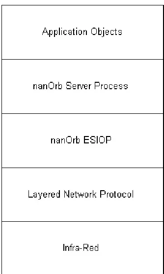
1.7 Project Achievements
A design for enabling the aforementioned functionality has been produced and facilitates the transparent invocation of embedded server object methods, from the client. The work in this report has been kept focussed on implementing the ESIOP and embedded ORB functionality. The bridging functionality has been implemented as a CORBA server application (as opposed to the ORB encompassed solution described in Figure 1) in order to demonstrate the design. Whereas a more complete solution would implement a non application-specific bridge as part of an ORB implementation, the time constraints involved would not permit this. This architecture necessitates that the gateway implements the specified IDL interface, but this should not be the case in a more complete solution.
Figure 2 The nanOrb Architecture
This current implementation illustrates the embedded device acting as a server for normal CORBA clients by translating between the necessary IIOP and ESIOP messages. It defines a message-set for the ESIOP
implementation and the data encoding rules. It also supports the
demonstration on inter-embedded system invocations via the ESIOP. It does not as yet facilitate the RCX making client requests of normal CORBA
1.8 Roadmap
The remainder of this document is divided, by chapter, according to the different work objectives of this research. Chapter two provides a background for each of the technologies utilised. The Common Object Request Broker Architecture is described in more detail, with particular attention to its more recent application to Embedded Systems, including several recent projects in this area. The GIOP specification is also described in more detail, detailing its individual components and messaging functionality. The LEGO Mindstorms Robotics Invention System is presented in more detail and the various development tools and environments available for it are reviewed. This chapter does not endeavour to fully explain each of these fields in its entirety, instead references are provided, where appropriate, to facilitate further reading.
Chapter three outlines the design objectives involved in mapping the GIOP specification onto an Environment Specific Inter-ORB Protocol and implementing embedded ORBs. Each of the design objectives is explored in detail and then developed through applying it to the Mindstorms environment. The intention is to illustrate the various configurations and customisations that are possible, and how they will ultimately effect the implementation.
The implementation of a test application (“nanOrb”) is described in chapter four. This application is used to verify the design presented previously. The technologies used and the application architecture is described in detail. Each of the components of the final application is documented along with the difficulties encountered and how they were overcome.
optimisations that can be made when implementing an ESIOP. The justifications for each of these are investigated and the ramifications explored. Ultimately this chapter describes the degree to which this work was successful in verifying CORBA’s success.
Chapter 2
Background
This chapter describes the main technologies relevant to this research, as outlined in the previous chapter. A number of relevant research papers and commercial products are also outlined, with a view to establishing the current ‘state-of-the-art’ in these areas. The overall aim of this chapter is to give the reader a context within which to place this work and aid further reading and/or development.
2.1 Embedded Systems
2.1.1 Overview
manufacturing systems and even such safety critical systems as airplane avionics.
The very simplest embedded systems are typically charged (programmed) with performing a simple function or set of functions to meet a single predetermined purpose. In the more complex embedded systems the operation of the embedded system is determined by some compiled code (a program), which enables the embedded system to do execute the logic of a specific application. This ability to program the system means that the same system, where flexible enough, can be used for a variety of different purposes. In some cases a microprocessor may be designed in such a way that application software for a particular purpose can be added to the basic software in a second process, after which it is not possible to make further changes: this is sometimes referred to as ‘firmware’.
The growth in utilization of programmable processors in embedded systems has largely been caused by the increase in availability of powerful, inexpensive processors and low-cost memory. However, perhaps the most exciting catalyst to this growth is the utilization of application oriented embedded systems within the Internet.
influence all embedded software implementations and hence how they might communicate.
2.1.2 Engineering Constraints
It is the physical resources of the embedded system that ultimately drive its final software implementation (be they originally cost or otherwise constrained). These constraints include specifications such as the target processor and its instruction set, memory availability (both RAM and ROM), and others arising from embedded operating systems/firmware and input and output capabilities and requirements [6]. These constrained systems are a direct result of the nature of the end product (or device) in which the system will operate. Household appliances for example, are more and more likely to utilise embedded system technology, yet due to the extremely competitive, cost-driven markets in which these manufacturers operate, the systems themselves are as economic, and implicitly constrained, as possible.
2.1.3 Embedded Systems in Distributed Environments
In the context of this report we will describe a distributed embedded system as “a system in which individual embedded systems running applications and communicating via some network medium are physically separated” [7]. As embedded systems are used more and more, (“Approximately 3 billion embedded CPUs are sold each year, with smaller (4-, 8-, and 16-bit) CPUs dominating by quantity and aggregate dollar amount” [8]), they increasingly need to communicate and interoperate with desktop and client-server installations [9].
be linked together via a separate high-speed serial bus such as the Controller Area Network (CAN) bus, which facilitates a greater degree of distribution and supports data rates of up to 1 Mbps. In order to support still further distribution, WAN protocols, such as the prevalent TCP/IP stack, are implemented in suitable devices. It is still, however, often considered far too expensive for smaller systems. Ultimately, although the underlying communications technology may not utilize a physical-connection, as the demand for mobility support increases, modern networks are based more and more on wireless communication.
Embedded Systems operating in distributed environment are also frequently subject to real-time constraints. As such, these systems must be designed so that tasks are always executed by a specified deadline. The particular deadline may a specific time, a time interval or indeed a discrete event [10]. This last statement describes the two key approaches to real-time systems design, the event-driven and time-driven models. The greater the frequency of these tasks and the potential for failure on missing the deadlines, the more the application exhibits ‘hard real-time’ requirements. Conversely, if missing a deadline will not necessarily compromise the system, the application is said to have ‘soft real-time’ requirements [10].
2.2 The Common Object Request Broker Architecture
(CORBA)
2.2.1 Overview
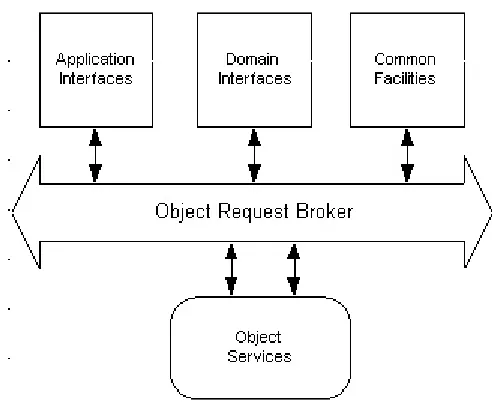
[image:24.595.172.418.517.718.2]The Object Management Group (OMG) was established in 1989 to create standards for distributed object computing. Its standards were intended to “allow interoperability of objects, component, and applications in a heterogeneous networked environment” [11]. Early work resulted in the Object Management Architecture (OMA), an abstract object model, providing concepts of object concepts and terminology. The Common Object Request Broker Architecture (CORBA) is an open distributed-object computing infrastructure that specifies a concrete object model, based on the OMA model. Its basic task is to handle requests between clients and object implementations, in a distributed environment. CORBA automates many common network programming tasks such as “object registration, location, and activation; request de-multiplexing; framing and error handling; parameter marshalling and de-marshalling; and operation dispatching” [1].
CORBA allows applications to communicate with one another no matter where they are located or who has designed them. CORBA 1.1 was introduced in 1991 by the OMG and defined the Interface Definition Language (IDL) and the Application Programming Interfaces (API) that enable client/server object interaction within a specific implementation of an Object Request Broker (ORB). It did not however, provide for the inter-working of different vendors ORBs, which typically used proprietary data representation and marshalling schemes.
CORBA 2.0 [1], adopted in December of 1994, defines true interoperability by specifying how ORBs from different vendors can interoperate using the General Inter-ORB Protocol (GIOP) specification, the standard implementation of this specification being the Internet Inter-ORB Protocol (IIOP), which utilises the TCP/IP protocol stack. All CORBA 2.0 compliant ORB implementations must support IIOP. This support facilitates a standard inter-orb communications mechanism.
2.2.2 The CORBA ORB
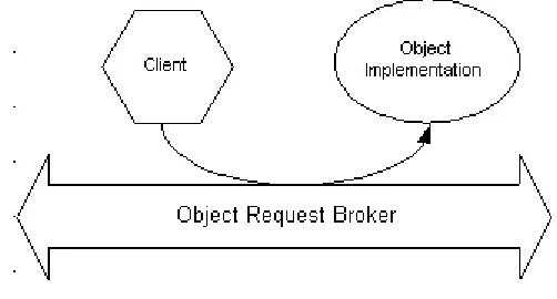
The core of CORBA is the ‘ORB core’, or middleware (‘Middleware’ is the software that resides between an application program and the base operating
systems and networking functions. Its purpose is to shield application
developers from complex low-level coding). The OMG defines the ORB as
In so doing, the ORB provides interoperability between applications on different machines in heterogeneous distributed environments.
Figure 4 An Object Request Being Sent Through the Object Request Broker
2.2.3 Interface Definition Language
The IDL was originally part of the Open Software Foundation's Distributed Computing Environment (DCE). It described function interfaces for Remote Procedure Calls (RPCs), so that a compiler could generate proxy and stub code that marshalled function parameters between machines. This same model is used in CORBA to define interfaces to remote objects and hence generate stub and proxy classes, which can be used by the programmer to provide the distributed object functionality. The programmer uses these classes in the normal way, without having to worry about their internal functionality, and object distribution is achieved.
2.2.4 CORBA Services
At the heart of every CORBA implementation, is the ORB core, that which provides the basic objects references and invocation functionality, hence enabling a client to transparently invoke the services of distributed objects implementations. In addition to this basic middleware functionality, the OMG has adopted a number of value-adding functions represented by middleware services called the Common Object Services (COS). CORBA services greatly extend the functionality provided by the core and some of are essential for the development and deployment of distributed applications. These services provided include, amongst others, centralised object name resolution, distributed event services and transactional support.
The OMG Naming Service is the simplest of the standard CORBA services. It essentially provides a mapping from object names to references. It is essentially a well-known repository that stores named object references. The key benefit of the OMG Naming Service is its distributed capabilities, and that it allows for stored object references to be accessed through a CORBA environment. Servers advertise themselves with the Naming Service by providing an object reference and an associated name at run-time, hence enabling clients to use the Naming Service to locate objects in a CORBA environment.
connections from one or more suppliers, and one or more consumers. An event is defined as any piece of data that has been generated as a result of some activity. The key is that any event received from one of the suppliers is transmitted to every consumer.
The Object Transactional Service enables transactional functionality in the CORBA environment. It is, in essence, a distributed transaction manager. It supports the inter-working of object-oriented and procedural transactional applications and includes support for the industry X/Open transactional standard.
2.3 The General Inter-ORB Protocol
2.3.1 Overview
The GIOP specification can be conceptually divided into three primary components:
1) The Common Data Representation 2) The GIOP Message Set
3) Transport Requirements
2.3.2 The Common Data Representation
The Common Data Representation (CDR) provides a common syntax for the transfer of IDL defined data. It defines the low-level binary, “on-the-wire” format of inter-ORB communications (ultimately byte streams).
The CDR standard itself has three key features:
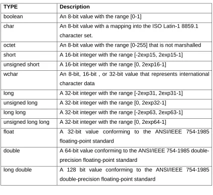
1) Variable Byte Addressing - The CDR supports both ‘little-endian’ and ‘big-endian’ architectures as there is no guarantee, in the heterogeneous distributed environment in which CORBA operates, that any two communicating devices will use the same byte addressing rules. Using CDR, the sender does not have to perform any byte swapping; this is the sole responsibility of the receiver. The actual byte-order of a message is flagged in the message protocol header, so the receiver knows how the message contents must be interpreted.
TYPE Description
boolean An 8-bit value with the range [0-1]
char An 8-bit value with a mapping into the ISO Latin-1 8859.1 character set.
octet An 8-bit value with the range [0-255] that is not marshalled short A 16-bit integer with the range [-2exp15, 2exp15-1]
unsigned short A 16-bit integer with the range [0, 2exp16-1]
wchar An 8-bit, 16-bit , or 32-bit value that represents international character data
long A 32-bit integer with the range [-2exp31, 2exp31-1] unsigned long A 32-bit integer with the range [0, 2exp32-1] long long A 32-bit integer with the range [-2exp63, 2exp63-1] unsigned long long A 32-bit integer with the range [0, 2exp64-1]
float A 32-bit value conforming to the ANSI/IEEE 754-1985 floating-point standard
double A 64-bit value conforming to the ANSI/IEEE 754-1985 double-precision floating-point standard
[image:30.595.83.513.86.480.2]long double A 128 bit value conforming to the ANSI/IEEE 754-1985 double-precision floating-point standard
Figure 5 GIOP Defined Primitive Data Types
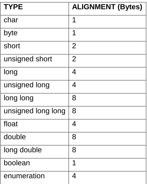
3) Naturally Aligned Primitive Types – THE CDR specifies that primitive data types should be aligned on their natural byte boundaries (that is the way most machine architectures would align them). Whereas this process is somewhat inefficient in its consumption of bandwidth, it is ultimately more efficient than a more compact representation, as data can be unmarshalled by simply ‘pointing’ at its binary value in memory. The alignment of a primitive data type is equal to the size of that type in bytes. Hence, a type of size N bytes must be positioned in an octet stream where the index is a multiple N. A gap may also be inserted in the stream to preserve this alignment.
TYPE ALIGNMENT (Bytes)
char 1
byte 1
short 2
unsigned short 2
long 4
unsigned long 4
long long 8
unsigned long long 8
float 4
double 8
long double 8
boolean 1
[image:31.595.172.412.110.410.2]enumeration 4
Figure 6 Octet Sizes of Primitive Data Types
2.3.3 The GIOP Message Set
2.3.3.1 Overview
The GIOP specification defines a set of eight messages (since version 1.1), which are considered sufficient to accomplish the functional objectives of CORBA. Whereas, s only two of these messages are actually required to achieve the basic remote invocation objectives of CORBA, the remaining six provide various, complimentary, functionality.
[image:32.595.167.431.320.511.2]
Figure 7 The 1.1 GIOP Messages
The FRAGMENT message was added in version 1.1 of the GIOP specification, to allow for the more efficient marshalling of data by the sender.
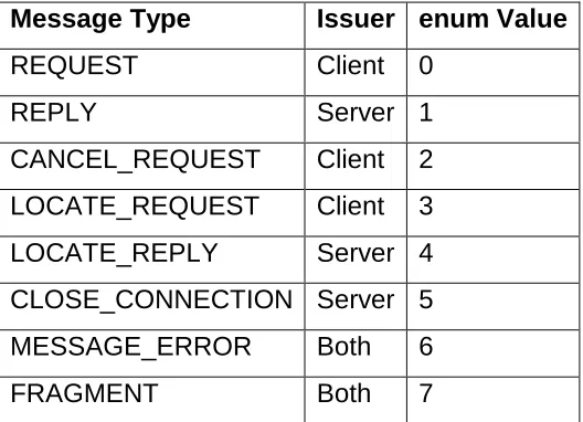
2.3.3.2 The GIOP Protocol Header
In order to transmit a GIOP message, the sender will fist include the protocol message header, a 12-byte header consisting of five fields, and then the message body, which is specific to the type of message being sent.
Message Type Issuer enum Value
REQUEST Client 0
REPLY Server 1
CANCEL_REQUEST Client 2
LOCATE_REQUEST Client 3
LOCATE_REPLY Server 4
CLOSE_CONNECTION Server 5
MESSAGE_ERROR Both 6
Module GIOP {
struct Version {
octet major;
octet minor;
};
enum MsgType_1_1 {
Request, Reply, CancelRequest, LocateRequest,
LocateReply, CloseConnection, MessageError, Fragment };
struct MessageHeader_1_1{
char magic[4];
Version GIOP_version;
octet flags;
octet message_type;
unsigned long message_size;
[image:33.595.96.398.68.382.2]}; };
Figure 8 The GIOP Protocol Header IDL
• The first four bytes always contain the characters ‘GIOP’, to indicate the message type.
• The fourth and fifth bytes contain the Major and Minor version numbers as binary values.
• The sixth byte is a flag, the least significant bit of which signifies whether the message is in big endian (0) or little-endian(1) encoding. The second bit is used to flag fragmentation.
• The seventh byte is used to indicate the type of the GIOP Message and corresponds to the numeric value of the appropriate
MsgType_1_1 enumeration.
2.3.3.3 The Request Message
The request message is used to encode object invocations and send them to the server. A complete request message consists of the aforementioned GIOP protocol header, a request message header and also the request message body. The latter two forming the GIOP message body.
module GIOP {
struct RequestHeader_1_1 {
IOP::ServiceContextList service_context;
unsigned long request_id;
boolean response_expected;
octet reserved[3];
sequence<octet> object_key;
string operation;
Principal requesting_principal;
};
};
Figure 9 The GIOP 1.1 Request Header IDL
• The ‘service_context’ is an IDL defined structure used by services such as transactional and security services to implicitly pass service information with requests and replies, transparent to the client.
• The ‘request_id’ field is an unsigned long integer value, used to uniquely identify a particular request, and also to relate response messages to their request messages.
• The ‘response-expected’ field is used to indicate whether a server response is expected in reply to a particular request. The value is set to false (0) for IDL specified ‘one-way’ functions.
• The ‘object_key’ field is the object key from the Interoperable Object Reference (IOR). This is a server specified value and has no relevance outside of the server’s scope.
• The ‘operation’ field contains a string value which indicates the relevant method to be invoked on an object
• The requesting principal field is used for security purposes in order to identify the requester. It is now deprecated, as the service context provides this information.
The body of the request message is an octet sequence containing the encoded IDL specified ‘in’ and ‘out’ parameters for the requested operation.
2.3.3.4 The Reply Message
The reply message is sent by a server in response to a client request. A complete reply message consists of the GIOP protocol header, a reply message header and also the reply message body. The latter two forming the GIOP message body. The reply message indicates the success or failure of a request, and (in the case of the former) also includes any IDL defined ‘out’ parameters of the associated method invocation.
module GIOP {
enum ReplyStatusType {
NO_EXCEPTION, USER_EXCEPTION,
SYSTEM_EXCEPTION, LOCATION_FORWARD
};
struct ReplyHeader {
IOP::ServiceContextList service_context;
unsigned long request_id;
ReplyStatusType reply_status;
}; };
• The ‘service_context’ field is used in the same way in the reply header as in the request header.
• The ‘request_id’ field returns the uniquely identifier of the associated request, hence a client does not have to wait for once request to complete before making another.
• The ‘reply_status’ field contains one of the ‘ReplyStatusType’ enumeration values and indicates the result of the request. The ‘LOCATION_FORWARD’ reply is used when a server cannot fulfil a particular request, but advices the client to try another address.
The body of the reply contains an octet sequence containing any ‘out’ parameters for the requested operation.
2.3.3.5 The Cancel Request Message
The ‘Cancel Request’ message is sent by a client to a server to indicate that the client no longer requires, or expects, a response to a particular request. A complete ’Cancel Request ‘message consists of the GIOP protocol header and the ‘Cancel Request’ message header.
module GIOP{
struct CancelRequestHeader{
unsigned long request_id;
}; };
The message header contains only the unsigned long ‘request_id’ field, which indicates the particular request to be cancelled. The server does not acknowledge the ‘Cancel Request’ message.
2.3.3.6 The Locate Request Message
The ‘Locate Request’ message is sent by a client to a server to determine whether a particular Interoperable Object Reference is valid. More specifically, it is a more bandwidth efficient method (as opposed to sending a complete request message) of determining of whether or not an object is available at a particular address. A complete ’Locate Request ‘message consists of the GIOP protocol header and the ‘Locate Request’ message header.
module GIOP{
struct LocateRequestHeader{
unsigned long request_id;
sequence <octet> object_key;
}; };
Figure 12 The GIOP Locate Request Header IDL
2.3.3.7 The Locate Reply Message
A server sends the ‘Locate Reply’ message to a client in response to the ‘Locate Request’ message. A complete ‘Locate Reply’ message consists of the GIOP protocol header, the ‘Locate Reply’ message header and the ‘Locate Reply’ message body.
module GIOP{
enum LocateStatusType{
UNKNOWN_OBJECT,
OBJECT_HERE,
OBJECT_FORWARD
};
struct LocateReplyHeader{
unsigned long request_id;
LocateStatusType locate_status;
}; };
Figure 13 The GIOP Locate Reply Header IDL
The message header contains an unsigned long ‘Request Identifier’ field and the ‘locate_status’ field, indicating the result of the ‘Locate Request’ message. The message body then contains the Interoperable Object Reference (IOR) of the requested object
2.3.3.8 The Close Connection Message
2.3.3.9 The Message Error Message
The ‘Message Error’ message can be sent by wither the client or server. It is sent when the protocol header of a received GIOP message indicates a protocol version that is not supported by the recipient.
2.3.3.9 The Fragment Message
If a GIOP client decides to use fragmentation, the first part of a request or response message is sent with the fragment bit in the protocol header set to true. The ‘Fragment’ message is used after these messages to pass further fragments of encoded data and also indicate whether more fragments are to follow. The ‘Fragment’ message exists to avoid necessitating the client marshalling of large messages in their entirety, before sending them.
2.3.4 Transport Assumptions
The GIOP specification makes certain assumptions of the underlying transport protocol [1]:
• It provides a reliable connection oriented service. A connection-oriented transport allows a host to open a connection to by specifying the address of the receiver. This process will typically return an identifying handle to that connection, which can then be used for the duration of communication without the need to specify the address for every the message sent.
• Connections must be full duplex. Upon a connection being
• The transport is reliable. The transport should ensure that any messages sent over a connection are received at the destination without duplication.
• The transport provides a byte-stream abstraction. The transport should ultimately be viewed as a ‘data-pipe’, once established. In this way, a communicating host can view a connection as a continuous stream of bytes and not have to deal with underlying networking issues such as fragmentation and re-transmission.
2.4 Object References
The CORBA specification describes an object reference as “an object name that reliably denotes a particular object” [11]. The ultimate aim of this reference is to facilitate the client utilizing the object in a location and implementation transparent way. The General Inter-ORB Protocol uses the Interoperable Object Reference (IOR) to identify objects.
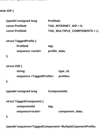
The IOR is a data structure that provides information on the type of object it references, the underlying transport protocols that support contacting it and optional further service information. The IOR is structure is defined in a flexible manner. This flexibility is intended to facilitate the addition of support for multiple transport protocols and their associated optional data.
optionally be included within a ‘TaggedProfile’ and is used to communicate extra service specific information.
module IOP {
typedef unsigned long ProfileId;
const ProfileId TAG_INTERNET_IOP = 0;
const ProfileId TAG_MULTIPLE_COMPONENTS = 1;
struct TaggedProfile {
ProfileId tag;
sequence <octet> profile_data; };
struct IOR {
string type_id;
sequence <TaggedProfile> profiles; };
typedef unsigned long ComponentId;
struct TaggedComponent {
componentId tag;
sequence<octet> component_data; };
[image:41.595.105.462.103.559.2]typedef sequence<TaggedComponent> MultipleCoponentProfile; };
Figure 14 The Interoperable Object Reference IDL
Hence an IOR can be defined for a server object, which contains end-point information for each specific protocol the server supports as well as optional extra ‘TaggedComponent’ data. In this way a server implementation can support existing and future protocols in a single published IOR.
order to identify a communications end-point using the TCP/IP transport, this will contain Hostname or IP address and a port number, thus enabling a client to locate a server implementation via the TCP/IP protocol.
2.5 CORBA and Embedded Systems
2.5.1 Overview
As has been described previously, the majority of implementations of the full CORBA specification consist not only of the ORB core functionality, but also several of the aforementioned CORBA services. Hence, these implementations tend to be quite large, in terms of their storage and memory requirements, and also computationally intensive to execute, even on modern day desktop computers. These implementations are hence not suitable to use in heavily resource constrained embedded systems.
The first of the two aforementioned options, the OMG Minimal CORBA standard, defines a subset of the full CORBA standard, which facilitates the implementation of more efficient and smaller footprint ORBs. The core changes in the standard are the removal of most of the dynamic facilities for creating and using objects; this decision was based on the assumption that “The background of embedded systems tends to require design-time decisions on resource allocation, object location and creation. Together with pre-determined patterns of interaction, this yields a much more predictable system environment” [2].
The standard attempts to “minimise the specification of unnecessary or costly services, whilst retaining maximum compatibility” [2] with the existing full CORBA specification. Support for the full set of CORBA IDL is retained; hence there is no barrier to implementations utilising any existing external CORBA services, when running in larger CORBA systems.
The second approach to facilitating embedded CORBA, is much lower level approach utilising an efficient ‘protocol engine’ to enable CORBA (GIOP) compliant communications on an embedded system. This ‘engine’ may be in the form of a third-party library or a proprietary implementation. These ‘engines’ ultimately facilitate the basic construction and deconstruction of GIOP compliant packets along with their transmission over the underlying protocol.
2.5.2 Embedded CORBA Research
There is a lot of research work in progress in the embedded CORBA domain. The focus of these efforts cover the two main approaches outlined previously, those of the minimumCORBA specification and customised low-level GIOP communications, utilizing both the Internet Inter-ORB Protocol (IIOP) and other Environment Specific Inter-ORB Protocols (ESIOPs). This section introduces some of the most relevant works and compares them to the focus of this report.
There are several commercial and research derived high-performance CORBA products in existence. ORB products such as ORBit [12], ORBacus [13], OmniORB [14] and the ACE ORB [15] are all built with a focus on high-performance.
The ACE ORB, for example, is a product of high-performance and real-time CORBA research at U.C.L.A. [16]. The ACE ORB (TAO), pronounced "dau", is an open source CORBA 2.2 compliant, C++ implementation. It more recently includes a minimumCORBA compliant implementation, which as a result of its component structure and open-source form does lend itself to application and customisation in the embedded environment.
The difficulty with all the aforementioned CORBA implementations is that although they are very efficient, their memory footprints and resource demands are still far too excessive for the more constrained of embedded systems.
The K-ORB Project [18] is one minimumCORBA research effort that is very relevant to this project. The project describes a minimumCORBA framework that facilitates the building of ORBs tailored to the particular requirements of the target environment. It implements a ‘pluggable framework’ facilitating the utilisation of different components of the K-ORB system as required. Using this architecture multiple networking protocols are facilitated and hence ESIOPs accommodated. This model and its architecture have been leveraged throughout this work and it is anticipated that the two projects will be integrated in the future.
For the more severely constrained of embedded systems however, all of these full minimumCORBA implementations are unattainable. GIOP compliant protocol engines can provide more efficient ORB core functionality for these devices. Products such as Sunsofts IIOP Protocol Engine [19] and IONA Technologies IIOP engine [3] enable IIOP messaging on these devices.
The [20] paper describes an environment specific CORBA implementation based on the Controller Area Network (CAN) bus. The report describes a “Compact Common Data Representation (CCDR)” [20] format, an optimised version of the CORBA CDR specification, which enables more efficient use of the small payload of the CAN bus (8 byte) message payloads, hence compromising processing speed for bandwidth efficiency. It further describes a customised (reduced) messages set, based on two of the eight GIOP specified messages, and message header format (again with a focus on increasing bandwidth efficiency). This work is an excellent demonstration of the environment driven constraints and resultant customisations that characterise embedded system development and hence will feature in any environment specific CORBA implementation.
2.6 The Lego Mind Storms Robotics Invention System
2.6.1 Overview
The Lego Mindstorms Robotics Invention System is a product manufactured by the Lego Company. It consists of conventional Lego bricks, along with a ‘programmable brick’ and several motors and actuators (touch and light sensors), which, collectively provide the building blocks of a simple but powerful robotics kit. Users can program and compile programs for constructed robots, using a PC based application, and download these to the robot via a wireless infrared link, which utilises the PC’s serial (RS-232) port and a small infrared transceiver (tower).
Group, which was originally started by Seymour Papert [21], the creator of the LOGO language/teaching environment.
Whereas the originally intended way to program Mindstorms robots was using the provided PC application, several language ports now exist which facilitate much greater flexibility and control in building applications. These range from Visual Basic enabling COM controls [22] to the NQC (‘Not Quite C’) language [23], a C like low-level language and even to replacement firmware in the form of pbForth [24]), tinyVM [25] and legOS [26].
2.6.2 The RCX Brick
The RCX brick is the battery powered programmable micro-controller that is the heart of the Mindstorms kit. It is contained in a single brick that is capable of operating three motors, three sensors, and the infrared communications interface. At the core of this brick is a Hitachi HD6433292 micro-controller that contains 16K of ROM and 512K or RAM and runs at a speed of 16Mhz. A further 32K of external RAM is also contained in the brick.
The 16K on-chip ROM contains a driver that is run when the RCX is first powered up. This driver facilitates the downloading of firmware to the RCX. The standard firmware occupies 16K of memory and facilitates downloading of user-compiled programs to the RCX that can then be interpreted and executed by the firmware.
2.6.3 The Development Process and Tools
The standard development environment supplied with the Mindstorms kit supports some simple but useful programming. It is a graphical environment, which allows the user to drag and drop RCX actions and events as building blocks for an RCX application. Once built the program is compiled to byte-code and downloaded to the robot, where the firmware of the RCX interprets this byte-code and controls the RCX (or the robot which is connected to) accordingly. The standard firmware itself controls the hardware interrupts, multi-threading and IR Port communications but is relatively limited from the developer’s perspective.
There are various tools in existence that facilitate the extension of the RCXs capabilities via replacing different portions of the architecture. The simpler varieties provide replacement compilation environments for the developer. The Not Quite C (NQC) language [23] and the ‘spirit.ocx’ COM control Holdren, 2000 #13] are two such examples which provide a more procedural programming environment, but still fall far short of exploiting the hardware’s full capabilities. There are also some TCL and Perl language interfaces that facilitate the run-time control of the robots.
2.6.4 LegOS and the Layered Network Protocol
LegOS essentially provides a multitasking (pre-emptive) operating system for the RCX. The operating system and its programs are written in standard C (with some C++ support) and then cross-compiled for the Hitachi chip using a GNU built compiler. Once the basic operating system is compiled and downloaded to the RCX as a replacement firmware, user programs can be compiled, downloaded and executed.
The development environment offers almost complete C language support, including semaphores, multi-threading, floating point emulation and the ability to store multiple programs (these programs are dynamically linked with the underlying legOS operating system).
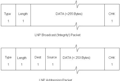
The most interesting feature of the more recent releases of the legOS environment however, is the Layered Network Protocol (LNP). LNP provides a simple networking abstraction to the underlying infrared transport mechanism. It facilitates the transmission of up to 255 bytes of data along with a checksum, to ensure integrity (this is known in LNP as an integrity packet). This mechanism acts like a broadcast channel for all listening hosts (where a host can be either an RCX brick or a PC enabled with the standard LEGO infrared tower). The protocol silently discards erroneous packets.
The API also provides an addressing mechanism where 2 bytes of the 255-byte payload of the integrity packet are used for addressing information, hence enabling the sending of a 253 byte addressed packet. A single byte is used for the source and destination addressing information. Each byte is then bit-masked to provide port information on each node. Hence it is possible to describe a host-port pairing to identify a communication end-point.
is assigned to, or an integrity (broadcast) packet. It is this transporting mechanism, coupled with the programming capabilities of the legOS environment, which makes the Mindstorms environment particularly suitable to an ESIOP implementation. That is, a server process can be created to handle data for a particular port on a specific host, that host-port pairing being a uniquely identifiable LNP transport end-point.
2.7 Mobile Applications
2.7.1 Overview
The advent of wireless communications technology and the subsequent proliferation of devices utilizing it have many ramifications for computer software, particularly distributed applications. There is a broad range of devices utilizing the technology, each with their individual characteristics. The one common attribute of these devices is their need for portability, if they are to support true mobility. Devices such as laptop computers, Personal Data Assistants (PDAs) and mobile phones are typical examples. These devices must be smaller in physical dimensions and lighter in weight, than their fixed-location (tethered) counterparts if they are to be used in a mobile environment and still strive to provide the same service to the user. The electronic component manufacturing industry has largely met these requirements, through the constant downsizing of chipsets and other device components, such as displays and battery-packs.
In conjunction with the requirements these technologies make of their physical attributes, they have large implications for the nature of the applications they host and indeed the way they are used. Whereas these applications can, and do, provide all the same functionality as their tethered counter-parts, they can also provide much further benefits to the user (such as location based services).
2.7.2 Communications Characteristics
wireless communications mechanism upon which these devices depend or not quite so unconstrained, they are subject to the limitation (or ‘coverage area’) of their infrastructure. A mobile phone user could for example potentially attempt to use the device anywhere on the planet whereas this attempt will only be successful if a supporting cellular network is available.
Not only must the wireless transport be available before communication can be attempted, but it must also remain available for the duration of the devices usage. This may seem like an obvious statement, but when the fact that the device may be moving (and the ‘coverage area’ of the underlying network is not) is considered along with the dynamic nature of most wireless communication mechanisms, it cannot be assumed. Radio-based mechanisms are subject to the inherent random nature of mobile radio devices; factors such as interference and signal reflection can practically annihilate a strong signal. This constitutes a significant departure from the assumptions of most fixed-network transports.
Chapter 3
Design
This chapter introduces the design goals relevant to building an Environment Specific Inter-ORB Protocol (ESIOP) and further develops these in the context of the LEGO Mindstorms environment. The aim is to not only introduce the generic ESIOP design process, but also to detail its application in the context of a specific environment.
3.1 Overview
The overall goal of this project is to investigate the suitability of CORBA middleware technology to resource-constrained embedded systems with a particular focus on mobile environments. The aim being to implement a minimal ORB (more specifically an ESIOP engine), on a severely resource limited platform (the LEGO Mindstorms RCX), along with an environment specific messaging protocol (an ESIOP implementation) to facilitate CORBA based communication with that ORB.
Hence this design must describe an Environment Specific ORB messaging protocol that includes:
1. A data representation syntax that specifies which of the standard IDL defined data types are supported and how they are encoded for transmission.
2. An ORB message set that is suitable to the environment. Some form of mapping between the GIOP message set and this set is also required if full CORBA functionality is to be supported.
3. An ORB transport mechanism which can provide the reliable byte-streaming service that CORBA implementations expect
4. A communication end-point mechanism such that individual server implementations can be reliable located.
5. An Object Addressing format that facilitates the reliable addressing of objects in the environment.
Once these, and hence the messaging protocol, have been defined the embedded ORB implementation can be addressed. The design of this embedded ORB, nanOrb, must support the aforementioned message set and provide as consistent an API as possible to the embedded applications it supports.
3.2 The Data Representation Syntax
The data representation standards for the ESIOP implementation must be defined. These must typically identify a distinct sub-set (or the full set) of the IDL defined data-types to support and an encoding syntax of each of these. The possibility of using a compact format (similar to that described in [20]) was explored, but is unnecessary due to the MTU size of the LNP transport being far more generous (253 bytes) than that of the CAN bus (8 bytes) used in the Kim project. The resource constraints in this application environment are more processing and storage than transport oriented. Hence, for the nanOrb implementation, a GIOP-like data representation scheme is implemented, preserving the natural memory alignment of data-types on 32-bit boundaries. The formats of the messages are based on version 1.1 of the GIOP standard. The full set of IDL defined primitive data types are supported.
3.3 The ORB Message Set
In any environment specific implementation a functional subset (or the full set) of the GIOP message set must be defined. In order to consistently present full CORBA services to clients, the functionality of the GIOP messages must be supported in some way. Rather than implementing the full GIOP message set in the nanOrb design, a subset of the standard 8 GIOP 1.1 specified messages set is identified that is deemed suitable to the environment.
As a consequence of the extreme resource constraints on the RCX, the memory footprint of the ESIOP engine must be kept minimal, if it is to work at all. A minimal number of messages are implemented in order to provide basic functionality and demonstrate the applicability of the CORBA to the environment. The number of these messages may be expanded in the future, but first it is necessary to determine how much of the limited memory resources these will consume and prove the concept. It is important to remember that ultimately, when implementing embedded CORBA, there will be a trade-off between the amount of memory utilized to provide CORBA functionality and the amount available for implementing application logic.
3.3.1 Client Initiated Messages
REQUEST – This message encodes an object invocation from a client to a
developed in future implementations, to provide, for example, security and transactional support.
Note; It is should be noted that this service contextual information could potentially be processed on the gateway (bridging) host, hence keeping the embedded ORB footprint to a minimum.
LOCATE_REQUEST – This message is used to check the validity of an
object reference and if a server will support a particular reference. The server may reply with a LOCATION_FORWARD type reply if it does not support an object locally. In particular this message is used in conjunction with an ‘Interface Repository’ (the Interface Repository provides run-time resolution of server implementations), so that a client can use a single ‘well-known address’ to resolve object references via the LOCATION_FORWARD reply. The request message will perform the same functionality although in a more expensive manner, that is, with a greater message payload (which contains all the invocation data, as opposed to just the Object Reference). It is, however, more expensive in the context of the Mindstorms environment, and many embedded systems (as our primary constraints are memory-footprint and processing oriented), to implement the processing necessary to facilitate the functionality of another message, than to send a greater sized packet over the underlying transport. Hence this message is not implemented in this design. It is worth noting that the ‘LOCATE’ functionality could be used by an IIOP client when talking to a gateway (or discovering it) to facilitate mobility support.
CANCEL_REQUEST – This message is sent by a client to cancel a previous
3.3.2 Server Initiated Messages
REPLY – This message is sent by the server if the ‘RESPONSE_EXPECTED’
flag is set in the request message. This can be used to return the results of an object invocation (where ‘OUT’ parameters are specified in the IDL) or simply a status. There is a REPLY_STATUS field in the header that can be used to indicate NO_EXCEPTION, hence reducing the need for a MESSAGE_ERROR message. This message is implemented. It is important, however, that the gateway’s call, to an RCX based object, is non-blocking. That is, the server should not wait for the receipt of a REPLY message before continuing. This is a departure from the GIOP model, but necessary due to the inherent unreliability of the infrared environment. Were the underlying transport of the ESIOP reliable, this optimisation would not be necessary.
LOCATE_REPLY - This message is sent from the server in response to
LOCATE_REQUEST message. It contains the results of a location attempt. It is not implemented, for the aforementioned reasons. It would not add any extra functionality in the RCX, and accommodating it would only serve to increase the memory consumption of the embedded ORB implementation. Again, it may be useful in facilitating location forwarding for IIOP clients using a gateway to request services of embedded devices (such as the RCX) in a mobile environment, where these devices may be in communication with different gateway’s at different times, depending on their location.
CLOSE_CONNECTION – This message is used to inform a client that it
and hence may need to notify clients as it reaches its concurrency limit and wants to cease offering its service temporarily.
This highlights another potential optimisation in an ESIOP application. If a single, or multiple interconnected, gateway(s) exist, which are aware at all times of the number of connections an embedded server is supporting, these gateways could assume responsibility for managing maximum numbers of connections, hence ‘protecting’ the servers from overloading, without the need for the server’s to implement this functionality.
3.3.3 Common Messages
MESSAGE_ERROR – This message is sent when either party detects an
error-condition as a result of a message. This is usually because of the incorrect formation of the message, or it’s containing an unsupported version number. This message is typically implemented, although the REPLY message does contain the functionality of flagging message errors. This message is implemented in the nanOrb environment, to facilitate the raising of exceptions when packets are incorrectly assembled and sent to the RCX. This will allow for the differentiation between the lack of an IR link and a ‘bad packet’ being the cause of a non-response from the RCX.
MESSAGE_FRAGMENT – This message is used when request or reply
3.4 The ORB Transport Protocol
Whereas the GIOP standard does not specify the transport protocol to be used, it does make certain assumptions as to the nature of this underlying transport mechanism. It expects a connection-oriented protocol, which the RCX network protocol, the Layered Network Protocol (LNP), does not provide. Through the provision of a connection-oriented transport, the need for acknowledgements of GIOP messages is alleviated. The lack of this functionality has some important implications for designs of this nature.
Any RCX based ESIOP implementation cannot make these same reliable transport assumptions, as the underlying communications medium (Infra-red) and environment cannot reliably facilitate a true connection-oriented service. A ‘best-effort’ implementation was attempted (whilst assessing the technology) involving an extra layer of abstraction between the ES-IOP and LNP layers, providing a TCP like timeout and re-transmit function. This did not provide and significant improvements over the simple LNP functionality, once the RCX was sufficiently out-of-range or subject to destructive interference, re-transmission provided no improvement.
Another solution, which is more inclined to correcting IR transmission problems, would involve the RCX based robot reorienting itself between attempts to establish communication (to aid finding a better line of transmission to the tower) or perhaps even retracing its navigation steps so as to return to the last known location of reliable communications (the cost of buffering commands and how to retrace them then becomes a constraining factor). These approaches are not included in the current implementation.
tower, but could perhaps provide a good demonstration of mobility support in a CORBA environment.
3.5 Communication End-Points
The concept of a communications end-point is necessitated within the underlying transport of any GIOP implementation. This end point must, typically, uniquely identify a server process on a particular host, which implements the functionality specified in the IDL interface for an object. Without this functionality, it is difficult to envisage an embedded device being able to provide a CORBA service to clients. In the case of IIOP this endpoint ultimately consists of an IP address and port number. LNP provides a very similar addressing mechanism (as described in chapter 2) where communication end-points are specified as host address, host port pairings. Using this system an individual packet can be addressed to a specific port (and hence a specific process) on a specific LNP host. An LNP host can be either an LNP enabled PC (using the LEGO Infra-Red tower) or an LNP enabled RCX brick. This system can be related very clearly to the IIOP addressing model, and facilitates the specification of LNP supporting Interoperable Object References.
3.6 An Object Addressing Format
The format of an IOR includes a specific ORB’s internal object reference as well as a transport based address for locating that ORB and hence the object (the IOR data structure is covered in more detail in chapter 2).
Any environment specific ORB implementation must specify a format for IOR’s. In the nanOrb architecture for example, not only does the client require an IOR for the gateway in order to communicate requests, but a means is required to locate object implementations within the embedded environment. As previously stated, the underlying transport must provide some means of identifying communication end-points, these are used to facilitate the protocol specific ‘Tagged Profile’ in an environment specific IOR format.
As a result of the current architecture implementing application-specific gateway functionality, it is not actually necessary to implement any further IOR support. The IIOP IOR for this gateway provides all the addressing information the client requires in order to make an object invocation on the RCX and the gateway is aware of the available servers. It is however necessary to further develop this architecture if true embedded CORBA functionality is to be supported in the nanOrb environment.
There were two possible IOR formats considered in this design process. The first involves extending the IIOP based IOR for the IIOP-ESIOP gateway host. This would involve adding a new ‘Tagged Component’ to the IIOP Profile ID, which would contain LNP addressing specifics enabling the gateway host to resolve RCX object references to specific RCX Host Address-Port pairs. Whereas this would enable the accurate addressing of the RCX from the Gateway, it is not a very exte