www.elsevier.com/locate/jmmm
Author’s Accepted Manuscript
The effect of magnetic annealing on barrier
asymmetry in Co
40
Fe
40
B
20
/MgO magnetic tunnel
junctions
G. Feng, J.F. Feng, J.M.D. Coey
PII:
S0304-8853(09)00435-1
DOI:
doi:10.1016/j.jmmm.2009.04.059
Reference:
MAGMA 55465
To appear in:
Journal of Magnetism and
Magnetic Materials
Received date:
25 September 2008
Cite this article as: G. Feng, J.F. Feng and J.M.D. Coey, The effect of magnetic annealing on
barrier asymmetry in Co
40
Fe
40
B
20
/MgO magnetic tunnel junctions, Journal of Magnetism
and Magnetic Materials, doi:
10.1016/j.jmmm.2009.04.059
Accepted manuscript
Contents lists available at ScienceDirectJournal of Magnetism and Magnetic Materials
journal homepage: www.elsevier.com/locate/agee
The effect of magnetic annealing on barrier asymmetry in Co
40Fe
40B
20/MgO magnetic
tunnel junctions
G. Feng* J.F. Feng and J.M.D. Coey
CRANN and School of Physics, Trinity College Dublin, Dublin 2, Ireland
A R T I C L E I N F O A B S T R A C T
Elsevier use only
Article history: Received date here
Received in revised form date here Accepted date here
Available online date here
Keywords: Magnetic tunnel junctions; Tunneling magnetoresistance; MgO barrier
We demonstrate that high quality magnetic tunnel junctions with Co40Fe40B20 electrodes and crystalline MgO barriers, which show a 230% tunnelling magnetoresistance ratio at room temperature, can be successfully fabricated by using a target-facing-target sputtering technical and present the results on the change of barrier asymmetry after the annealing at different temperatures. Bias voltage dependence of magnetoresistance ratio for Co40Fe40B20/MgO magnetic tunnel junctions is highly asymmetrical in the as-deposited states and becomes more symmetrical after magnetic annealing. It also exhibits a shift of the tunneling magnetoresistance maximum to a positive bias voltage under the low temperature annealing. © 2009 Elsevier B.V. All rights reserved.
______________
* Corresponding author. Tel.: 353 1 8963034; fax: 353 1 8963037.
E-mail address: gfeng@tcd.ie.
1. Introduction
Since the significant TMR values were reported in 1995[1-2], magnetic tunnel junctions (MTJs) emerged as a promising component for magnetic sensors and magnetic random access memory (MRAM). The application of MgO tunnel barriers in magnetic tunnel junctions has recently enhanced tunnel magnetoresistance (TMR) values to more than 200% at room temperature [3-5]. With its high magnetic field sensitivity, good MTJs with MgO barriers are suitable MTJ applications. The high TMR in these devices is due to the spin filter effect of the crystalline MgO barrier. The barrier is relatively transparent for the majority spin electrons injected from an oriented bcc Fe or Fe-Co electrode but attenuates the minority spin electrons, as result of the different symmetry of the ↑ and ↓ wavefunctions [6-7].
Usually two steps are essential in order to obtain high TMR ratio for Co40Fe40B20/MgO MTJs, the formation of crystallized MgO barrier and post magnetic annealing. Molecular beam epitaxy is the most effective way to fabricate MTJs with crystalline barrier. S. Yuasa et al has reported 180 % TMR in full epitaxial Fe (001) / MgO (001) / Fe (001) MTJs [3]. However it is a challenge to produce highly oriented (001) MgO barrier just by sputtering. In 2004, Stuart Parkin’s group from IBM [4] demonstrated high TMR in sputtered MgO based MTJs for the first time by preparing crystallized MgO barrier using reactive magnetron sputtering4. Shortly after that, the Japanese company Anelva [5] introduces another commercial solution to produce high quality MgO-based MTJs. In this technique, Co40Fe40B20 produced by conventional DC sputtering is used as the ferromagnetic (FM) layer, and the MgO barrier is grown directly by RF sputtering from an MgO target. The sputtering system has a unique feature of large distance and offset configuration between substrates and targets. Furthermore, compared with conventional sputtering system, the sputtering gas pressure can be reduced by one order of magnitude in
their sputtering tools. By using this sputtering technique, a highly oriented thin (001) MgO layer can be grown on the top of the amorphous ferromagnetic layer. Here we report the successful fabrication of high TMR Co40Fe40B20/MgO MTJs by using the target-facing-target (TFT) sputtering techniques and the change of barrier asymmetry after the annealing at different temperatures.
2. Experiment
Single barrier MTJs were grown by magnetron sputtering (DC and RF) on thermal-oxidized Si substrates in a Shamrock deposition system (base pressure around 3 X 10• 7 Torr), which consists of two sputtering chambers. All the metal layers are deposited in the main sputtering chamber and the MgO barrier layer was deposited by RF sputtering from a target-facing-target (TFT) gun. In order to establish exchange bias, the wafers were placed in an in-plane magnetic field of 5 mT during the metal deposition. Junctions with the size of 100 X 100 ì m2 to 20 X 20 ì m2 were fabricated by UV-lithography and Ar ion milling techniques. The annealing process was performed in a vacuum furnace under a magnetic field of 800 mT. The typical temperature ramp-up rate and dwell time were 100C/min and 90 minutes. X-ray diffraction measurement was conducted for structural characterization by using a Philips analytical X-pert Pro diffractometer with Cu Ka radiation. The magnetic property was measured by alternating gradient force magnetometer (AGM). The transport properties were measured by a standard four-point method.
3. Results and discussions
Accepted manuscript
2 Author name / Journal of Magnetism and Magnetic Materials 00 (2009) 000–000are shown in Figure 1. For the as-deposited MTJs (Fig. 1 (a) and (c)), the switching of the pinned layer and free layers is not well defined due to the weak exchange bias after sputtering. The exchange field (Hex) is only 23 mT and coercivity (Hc) of the free layer is 7 mT. The
small difference between Hex and Hc for the as-deposited MTJs leads
to simultaneous magnetization reversal of the free and pinned ferromagnetic layers. This means that a full antiparallel configuration between free and pinned layers can not be realized before annealing, which results a small TMR ratio of only 18%. A huge increase of the TMR ratio from 18% to 230% can be achieved after annealing at 350oC for 1 hour under an 800 mT field, as shown in Fig. 1 (b). The Hc for the free layer is around 1 mT. A large Hex
around 40 mT was established after the annealing process. Therefore a well-defined and stable anti-parallel configuration between free and pinned layers was realized from 40 mT to 0 mT (Fig. 1 (d)).
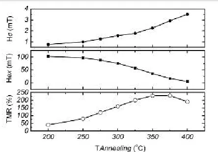
The annealing temperature effect on the TMR ratio, exchange bias (Hex) and coercivity of the free layer (Hc) are summarized in Fig. 2. By
increasing annealing temperature (Ta) up to 375oC, the TMR ratio
increases linearly from few percent in the as-deposited state to 230%. The TMR begins to drop at 4000C. This is mainly thought to be due to the diffusion of Mn and Ru into the MgO barrier [8]. Also as we can see, Hex decreases with the increasing annealing temperature,
but the Hc of CoFeB layer increases. At low Ta, for example 200oC, the
annealed samples show a Hex of 103 mT and Hc of 0.77 mT. After
annealing at 375oC, although H
ex decreases to 17 mT and Hc increases
to 3 mT, the bottom pinned and top free CoFeB can still switch independently following the change of magnetic field. A Hex of 5 mT
and Hc of 3.5 mT can be seen for the samples annealed at 400oC. The
small difference between those two values results in simultaneous magnetization reversal of pinned and free layer. No perfect anti-parallel configuration can be obtained in this case. This could be another reason for the drop of TMR ratio at high annealing temperature.
Fig. 1. The room temperature magnetoresistance and magnetization loop for as-deposited (a), (c) and annealed (b), (d) MgO-based magnetic tunnel junctions.
Fig. 2. Annealing temperature dependence of TMR ratio, Exchange bias field (Hex) and free layer coercivity (Hc).
Fig. 3 (a) shows the normalized TMR ratio as a function of applied bias voltage for a 325oC annealed sample. The TMR ratio decreases with the increasing negative / positive bias voltage and dropped to half its value at 600 mV at negative bias (- V1/2) and about 900 mV at positive bias (+ V1/2). A relative large ÄV1/2 of 300 mV, which is defined as the difference between - V1/2 and + V1/2, indicates a highly asymmetrical bias dependence for the samples annealed at this temperature. At the same time, the maximum value of the TMR wasn’t obtained at zero bias but at +15 mV (as shown in the inset).
[image:3.612.322.544.62.217.2]Accepted manuscript
Fig. 3. (a) Normalized TMR ratio as a function of bias voltage for a 325oC annealed sample (b) Energy diagram for the MgO-based MTJs with a asymmetrical barrier.
The bias dependence of the TMR ratio curves for the SMTJs annealed at different temperature have been put together in Fig. 4 (a) and (b). A clear change from asymmetric bias dependence to a more symmetric one can be observed with increasing annealing temperature. The samples annealed at 200oC show a ÄV
1/2 of 620 mV (with a -V1/2 =480 mV and ÄV1/2 = 1100mV). The value of ÄV1/2 decreases to 160 mV after annealing at 350oC. The bias dependence curve becomes more symmetric. Figure 4 (b) is compilation of bias dependence curves in the low bias region. The shifts of maximum MR (Vbias) were 42 mV and 0 mV for samples annealed at 200oC and 350oC respectively.
Fig. 4. Normalized TMR ratio as a function of bias voltage for sample annealed at different temperatures (a) high bias region (b) low bias region
[image:4.612.67.289.63.377.2]The shift of maximum TMR (Vbias) has been reported in single barrier AlOx-based MTJs, which is explained in two different ways, but not in the case of MgO-based MTJs. Sato et al[11] consider Co-Al interdiffusion and a change in band structure after annealing as a possible cause; Oepts et al[12] believe the barrier asymmetry Äφ can be the reason for the asymmetric bias dependence and shift of maximum MR according to their observations. The calculations of the later group clearly showed the change from asymmetric to symmetric bias with decreasing Äφ. They also assumed the change of the barrier height (Äφ) was related to oxidation time in the preparation of the AlOx barrier.
Fig. 5. Demonstration of the asymmetric bias dependence changing with the value of Äφ based on Opets’ calculations.
[image:4.612.324.534.540.699.2]Accepted manuscript
4 Author name / Journal of Magnetism and Magnetic Materials 00 (2009) 000–000course, the results should be interpreted only as an indication of the effect of the asymmetry of potential barrier on asymmetry of the TMR versus bias voltage in our MgO-based MTJs. The changing of the bias dependence curves with decreasing Äφ is very similar to its evolution with the increasing annealing temperature. So it is reasonable to speculate that the shift of maximum TMR (Vbias) could be a result of the change of Äφ during the annealing process. A large difference of barrier height between the bottom and top electrodes (Äφ) for as-deposited or low-temperature annealed samples will result in a shift of the maximum TMR (Vbias) to positive bias. With the increasing annealing temperature (T1 > T2 > T3 as indicated in Fig. 5), Äφ decreases. The maximum TMR (Vbias) will shift to zero bias as the bias dependence curves become more symmetric.
4. Conclusion
We observed the symmetry change of the bias dependence and the shift of maximum TMR in high TMR MgO/CoFeB MTJs during the annealing process. The junctions annealed at 200oC show a large ÄV1/2 of 620 mV. This value decreases to 160 mV after annealing at 350oC. The shifts of maximum MR (V
bias) also decrease from 42 mV to 0 mV when the annealing temperature increases from 200oC and 350oC respectively. The change of asymmetric bias dependence and shift of maximum MR can be attributed to the barrier asymmetry (Äφ) change during the annealing process based on Opets’ calculations.
Acknowledgements
This work was supported by European Biomagsens program and the Science Foundation Ireland as part of the CINSE program.
References
[1] J.S. Moodera, L.R. Kinder, T.M. Wang, R. Merservey, Phys. Rev. Lett. 74 (1995) 3273.
[2] T. Miyazaki, N. Tezuka, J. Magn. Magn. Mater. 139 (1995) L231.
[3] S. Yuasa, T. Nagahama, A. Fukushima, Y. Suzuki, and K. Ando, Nat. Mater. 3, (2004) 868
[4] S. S. P. Parkin, C. Kaiser, A. Panchula, P.M. Rice, B. Hughes, M. Samant, and S-H Yang, Nat. Mater. 3 (2004) 862.
[5] D. D. Djayaprawira, K. Tsunekawa, M. Nagai, H. Maehara, S. Yuasa, Y. Suzuki, and K. Ando, Appl. Phys. Lett. 86 (2005) 092502.
[6] W.H. Butler, X.-G. Zhang, T.C. Schulthess, and J.M. MacLaren, Phys. Rev. B 63 (2001) 054416.
[7] J. Mathon and A. Umerski, Phys. Rev. B 63 (2001) 220403
[8] X. Y. Liu, D. Mazumdar, W. F. Shen, B. D. Schrag, and G. Xiao, Appl. Phys. Lett. 89 (2006) 023504
[9] X. Zhang, B. Z. Li, G. Sun, and F. C. Pu, Phys. Rev. B 56 (1997) 5484 [10] T.Noizaki et al., Phys. Rev. Lett, 96 (2006) 027208
[11] M. Sato, H. Kikuchi, and K. Kobayashi, IEEE Trans. Magn. 35 (1999)2946 [12] W. Oepts, M. F. Gillies, R. Coehoorn, R. J. M. van de Veerdonk, and W. J. M. de