Table of Contents
Section 1 INTRODUCTION
The Manual ••••••••••••••••• _ •••••••••••••••••••••••••••••••••••••••••••••••• 1-1 How to Use this Manual ••••••••••••••••••••••••••••••••••••••••••••••••••••• 1-1 An Architectural Overview •••••••••••••••••••••••••••••••••••• ~ ••••••••••••• 1-2 The CPU, RAM, and ROM •••••••••••••••• , •• ~ ••••••••••••••••••••••••••••••••••• 1-5
Memory Cartridges •••••••••••••••••••••••••••••••••••••••••••••••••••••••••• 1-5 The Display Processor and Graphics Coprocessor ••••••••••••••••••••• ~ ••••••• 1-5 The Custom Sound-Processor •••••••••• ' •••••••. _ ••••••••••••••••••••••••••••••• 1-6 The Keyboard Processor and Associated Devices ••••••••••••••••••••••••••.•••• 1-6 I/O Devices •••••••••••••••••••••••••••••••••••••••••••••••••••••••••••• eo • • • 1-6
The Expansion Unit ••••••••••••••••••••••••••••••••••••••••••••••••••••••••• 1-7 Section 2
INTRODUCTION TO ReM BIOS OPERATION
How to Use the ROM BIOS Entry Points •••••••••••••••••••• ~ •••••••••••••••••• 2-1 Recommended Programming Techniques ••••••••••••••••••••••••••••••••••••••••• 2-1 Industry-Compatible Functions •••••••••••••••••••••••••••••••••••••••••••••• 2-1 System Interrupts •••••••••••••••••••••• ~ ••••••••••••••••••••••••••••••••••• 2-2 Mindset-Native Entry Points •••••••••••••••••••••••••••••••••••••••••••••••• 2-3 How this Manual Groups BIOS Functions •••••••••••••••••••••••••••••••••••••• 2-9
Section 3
INDUSTRY-COMPATIBLE BIOS FUNCTIONS
Page
1DH ••••••••••••••••••••••••••••••••••••••• 3-42
Video Parameters -- Interrupt
Diskette Parameters -- Interrupt 1EH •••••••••••••••••••••••••••••••••••• 3-42 Video Graphics Characters -- Interrupt 1FH ••••••••••••••••••••••••••• ~ •• 3-43 Hardware Interrupt Priorities ••••••••••••••••••••••••••••••••••••••••••••• 3-43
Section
4
MIHDSET-HATIVE GRAPHICS OPERATION
Overview of Graphics Operation ••••••••••••••••••••••••••••••••••••••••••••• 4-1
Two Processors . . . 4-1 Screen Orientation ••••••••••••••••••••••••••• ~ ••••••••••••••• •.••••••••••• 4-2
Display Processor Operation •••••••••••••••••••••••••••••••••••••••••••••••• 4-2
Screen Format Control ... -... 4-2 Double Buffering ....•..•..•..•••••..•••••.•••.•••••••.•••••••.••••••••••• 4-3 Color Palette Control ••••••••••••••••••••••••••••••••• ~ ••••••••••••• ••••• 4-4
Display Interrupt Control and VBLANK Operations •••••••••••••••••••••••••• 4-5 External Video Synchronization ••••••••••••••••••••••••••••••••••••••••••• 4-1 Descriptions of Display Processor BIOS Commands •••••••••••••••••••••••••••• 4-8 Effect of Display Processor,~lbmmands on Graphics
Coprocessor Operation ... . ~~~; ~ ... , ...•.... . 4-23 The SET SCREEN MODE and SWITCH ACTIVE BUFFER Commands ••••••••••••••••••• 4-23 The SET PALETTE Command ••••••••••••••••••••••••••••••••••••••••••••••••• 4-23
The Display Interrupt ••••••••••••••••••••••••••••••••••••••••••••••••••.• 4-24
Graphics Coprocessor Operation: Image Creation and
Block Transfer Operations ••••••••••••••••••••••••••••••••••••••••••••••• 4-24 Collision and Clip Detection •••••••••••••••••••••••••••••••••••••••••••• 4-24 Custom-Character-Set Operations ••••••••••••••••••••••••••••••.••••••••••• 4-26 Graphics Techniques ••••••••••••••••••••••••••••••••••••••••••••••••••••••• 4-21 Initialization and Mode Selection ••••••••••••••••••••••••••••••••••••••• 4-21 Double-Buffered Video RAM Operation •••••••••••••••••• ~ •••••••••••••••••• 4-28 Object Definition, Location, and Status ••••••••••••••••••••••••••••••••• 4-28 Collision and Clip Detection •••••••••••••••••••••••••••••••••••••••••••• 4-28
Block Transfer •••••••••••••••••••••••••••••••••••••••••••••••••••••••••• 4-29 Interrupt Handling •..••.•••••••••••.••••••••••••••••••••••••••••••••••••• 4-29
Orientation of Screen Images •••••••••••••••••••••••••••••••••••••••••••• 4-30 Descriptions of Graphics Coprocessor BIOS Commands •••••••••••••••••••••••• 4-30
Section 5
CUST<M SOUND-PROCESSOR OPERATION
Overview of Sound-Processor Operation •••••••••••••••••••••••••••••••••••••• 5-1 Sound-Processor Operating Modes •••••••••••••••••••••••••••••••••••••••••••• 5-1
Music Mode Operation ••••••••••••.•••.•••••••••••••••••••••••••••••••••••• 5-1
Sound Effects/Music Mode Operation ••••••••••••••••••••••••••••••••••••••• 5-2
Max Voice Mode Operation ••••••••••••••••••••••••••••••••••••••••••••• •••• 5~2 See-Through Mode Operation ••••••••••••••••••••••••••••••••••••••••• · •••••• 5-2 Sine Table Address Mask Operation •••••••••••••••••••••••••••••••••••••••••• 5-2
Noise Mask Operation ••••••••••••••••••• ~ ••••••••••••••••.••• , •••• ••••••••••• 5-3
.,
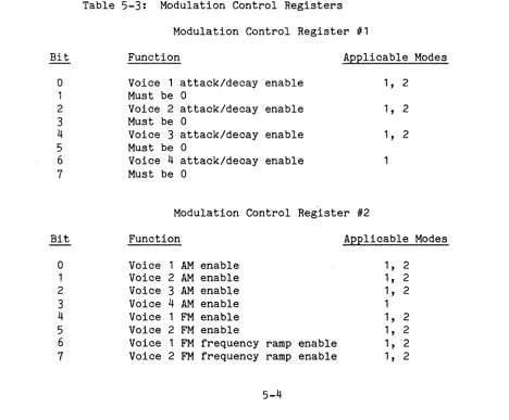
Custom Sound-Processor Registers •••••••••••••••••••••••••••••••••••••••••••. 5-3Modulation Control Registers ••••••••••••••••••••••••••••••••••••••••••••• 5-4 Attack/Decay Control ••••••••••••••••••••••••••••••••••••••••••••••••••••• 5-5 AM Control ••••••••••••••••••••••••••••••••••••••••••••••••••••••••••••••• 5-5 FM Control ••••••••••••••••••••••••••••••••••••••••••••••••••••••••••••••• 5-6 FM Frequency Ramping ••••••••••••••••••••••••••••••••••••••••••••••••••••• 5-6 Descriptions of Sound-Processor Commands ••••••••••••••••••••••••••••••••••• 5-6
Section 6
KEYBOARD OPERATION
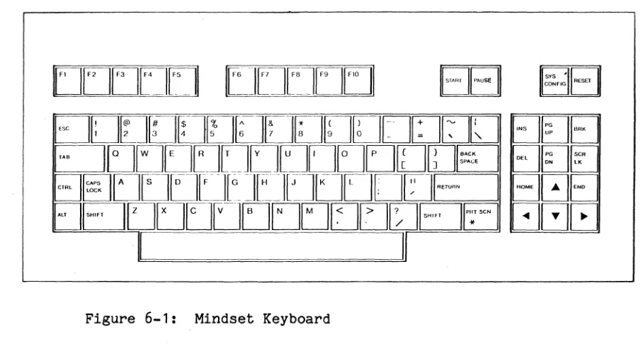
Introduction .•••••••••••••.••.••..••. ' .••..•.••••••••••••••••••••••••••••••• 6-1 Keyboard Compa ti bil i ty ••••••••••••••••••••••••••••••••••••••••••••••••••••• 6-1
The SYS CONFIG Key ••••••••••••••••••••••••••••••••••••••••••••••••••••••••• 6-2 Section 7
HINDSET REAL-TIME CLOCK OPERATION
Overview of Real-Time Clock Operation •••••••••••••••••••••••••••••••••••••• 7-1
I
Descriptions of Real-Time Clock Commands ••••••••••••••••••••••••••••••••••• 7-1
Section 8
RAM CARTRIDGE OPERATION
Overview of RAM Cartridge Operation •••••••••••••••••••••••••••••••••••••••• 8-1 Descriptions of RAM Cartridge Operation Commands ••••••••••••••••••••••••••• 8-3
Section 9
HIRDSET-NATlVE COMMUNICATIONS
Overview of Mindset-Unique RS-232-C Communication Capabilities ••••••••••••• 9-1 Descriptions of RS-232-C and Modem Commands •••••••••••••••••••••••••••••••• 9-1
Section 10
MISCELLABEOUS BIOS COtMANDS
Appendix C
TABLE OF KEYBOARD SCAN CODES
Appendix D
SYSTEM MEMORY HAP
Appendix E
SYSTEM STACK USAGE
Software Interrupts ... e . • • • • • • • • . • • • • • • • • • • • • • • • • • • • • • • • • • • • E-1 Ha~dware Interrupts •••••••••••.••••.••••••••••••••••••••••••••••••••••••••• E-4
Appendix F
SOURD FREQUENCY TABLE
Appendix G
Figure 1-1: Figure 4-1: Figure 4-2: Figure 4-3: Figure 4-4: Figure 6-1 : Figure 6-2: Figure 10-1:
List of Figures
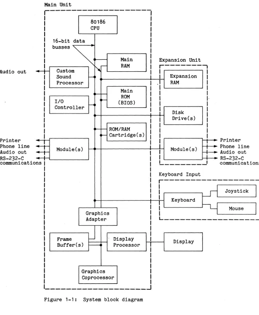
System block diagram . . . • . . . • . . . 1-4
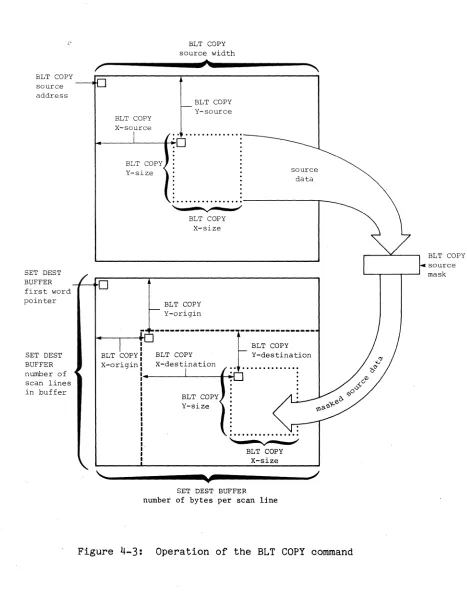
Definition of bits within a color palette entry •••••••••••••• 4-4 Screen layout of the Mindset Personal Computer ••••••••••••••• 4-6 Operation of the BLT COPY command •••••••••••••••••••••••••••
4-31
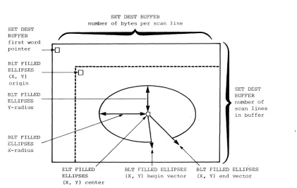
Operation of BLT FILLED ELLIPSES command •••••••••••••••••••• 4-61
Mindset keyboard ••••••.•.•••••••••••••.•••••••••••••••••••••• 6-1
Table 2-1 : Table 3-1 : Table 4-1 : Table 4-2: Table 5-1 : Table 5-2: Table 5-3: Table 5-4: Table 5-5: Table 8-1 : Table 8-2:
List of Tables
Interrupt Vectors •.•••••••••••••••••••••••••••••••••••.•••••• 2-2
Hardware Interrupt Priorities ••••••••••••••••••••••••••••••• 3-43 Graphics Display MOdes ••••••••••••••••••••••••••••••••••••••• 4-9 Mindset Graphics Modes •••••••••••••••••••••••••••••••••••••• 4-29 Custom Sound-Processor Operating Modes ••••••••••••••••••••••• 5-1 Frequency Control Conversion Factors ••••••••••••••••••••••••• 5-4 Modulation Control Registers ••••••••••••••••••••••••••••••••• 5-4
CSP Selection . . . 5-1
Section 1 INTRODUCTION
. THE MANUAL
This manual explains the operation of the Mindset Personal Computer from the point of view of an applications programmer. This manual refers to the appli-cations programmer as "the user".
The descriptions in this manual are of basic operations in the Mindset com-puter. Many descriptions involve loading registers in the Intel 80186 micro-processor and interpreting bit fields in status registers. Familiarity with assembly language programming is therefore fundamental to understanding the descriptions in this manual.
You may find the following references useful while reading this manual: 1. Intel 80186 Hardware Reference Guide
2. Intel iAPX 86/88 186/188 User's Manual
3.
Principles of Interactive Computer Graphics, by Newman and Sproull. (This is a standard graphics reference book, useful for defining terminology used in this manual.)This manual emphasizes the use of software entry points (as opposed to direct hardware access) to avoid hardware-dependent programming. Hardware-dependent programming causes problems when the hardware is changed and upgraded. The use of software entry points protects against program obsolescence.
HOW TO USE THIS MANUAL
This manual is organized from general to specific. In each section and in the manual as a whole, introductory material comes first and operational details are described later.
Some conventions used in this manual are:
Section 2 is an introduction to ROM Basic Input/Output System (BIOS) opera-tion. The ROM BIOS provides all the fundamental commands on the Mindset computer.
Section 3 describes the industry-standard BIOS functions that the Mindset com-puter provides. This section also describes the incompatibilities between the industry-standard and MindsetBIOS systems.
Section 4 describes Mindset-unique graphics operations. These operations go far beyond industry-standard graphics capabilities and support diverse graph-ics creations.
Section 5 describes custom sound-processor (CSP) operations in the Mindset computer. As with the graphics operations, Mindset provides a number of fun-damental procedures in sound generation that support the production of a wide variety of sound creations.
Section 6 gives some basics on keyboard operations and features. Section 7 describes the real-time clock and its operations.
Section 8 covers RAM/ROM cartridge features and operations in the Mindset computer~
Section 9 details the communications capabilities of the Mindset computer. Section 10 covers miscellaneous BIOS commands offered on the Mindset computer. Finally, Appendices A through G provide error messages, ASCII codes, keyboard scan codes, a system memory map, system stack usage information, a sound fre-quency table, and a sound generator sine-value table.
AN ARCHITECTURAL OVERVIEW
The Mindset computer system consists of a main system board/unit, the key-board, an optional expansion unit, and a display (not supplied).
The main system board includes the Intel 80186 CPU, the display processor, the graphics coprocessor, two frame buffers, the custom sound-processor, the
input/output (I/O) controller, the main read-only memory (ROM), the main random-access memory (RAM), and the bus interconnections structure.
The main system board is housed in the main System Unit. The main System Unit also houses two cartridge slots and the main double- and single-width I/O mod-ule ports. Cartridges can be plugged into the main unit to provide additional RAM and/or ROM features.
The Expansion Unit contains additional RAM, the one or two disk drives, and the expansion double- and single-width liD module ports.
Modules that plug into the main unit or Expansion Unit include an RS-232-C Module, a Stereo Sound Module, a Printer Interface Module, and two types of Modem Modules.
The display for the Mindset computer can be a red-green-blue (RGB) monitor, a composite video monitor, or a television set.
Main Unit
r---I
80186
I
I CPU
I
I 16-bit data I
I I
Main
I
.--Iludio out
buss.s ~
4
Custom ~- RAMSound i
Printer Phone line Audio out RS-232-C cOlDIDunicatio
~
Processor I
Main I
...--
-
ROM II/O ~
(BIOS) 1
~ 1
Controller I
I
i
ROM/RAM 1
...--
-1
~ Cartridge(s)
I
=+
Module(s)I
=+
I1
ns 1
I 1 1 I I I
I
Graphics I
Adapter 1
I
J
11
Frame Display 1
Buffer(s) ~ Processor
I
I I I
Graphics I
Coprocessor I
I
---~--~
Figure 1-1: Syste~ block diagram
Expansion Unit
r---,
I I
I Expansion I -I RAM I 1
1 I
I
I·
I 1
I
Disk I1 1 Drive(s) 1
1 1
I 1
I 1
I
!
PrinterModule(s)
:
Phone lineI Audio out
i
I
L _______
..J
RS-232-C cOlDIDunicatio Keyboard Inputr---I
1 Joystick
I Keyboard
I
Mouse [image:13.612.44.561.58.686.2]THE CPU, RAM, AND ROM
The CPU of a computer is its heart. It performs the basic operations neces-sary for reading intructions and executing them. The CPU performs program execution, logical comparisons, arithmetical operations, interrupt processing, and memory storage and retrieval. The CPU directs operations in the rest of the system, delegating some operations (such as input/output) to other devices as possible.
RAM is the main storage component in the system. For example, programs and data read into the system from disk are stored in RAM. It provides quick storage and access to data regardless of position in memory.
ROM provides system operations that are more complex than the basic operations of the CPU--the program routines in system ROM are, in fact, made up of the fundamental operations provided by the CPU.
MEMORY CARTRIDGES
Memory cartridges are options that provide extra RAM, extra ROM, or both. Extra RAM supports more complex programs and larger amounts of data, while extra ROM can provide new functions to the basic system set.
THE DISPLAY PROCESSOR AND GRAPHICS COPROCESSOR
The display processor performs the chores necessary for displaying bits of information on a cathode ray tube (CRT). The image on a CRT, which consists of hundreds of individual dots (pixels), must be refreshed or updated sixty times per second. If the CPU had to do this job, it would not have much time to do anything else. Therefore, the CPU delegates the job of maintaining a video display to the display processor.
The display processor in the Mindset computer also handles the two frame buf-fers. A frame buffer is a block of memory that can store the bits that define an entire video screen image. The second frame buffer gives the user the capability of creating an image in the inactive buffer and then switching buf-fers for instantaneous screen changes. Building images in an active frame buffer may be too slow or distracting for a particular application.
The graphics coprocessor (GCP) creates the graphic images in the frame buf-fers. It supports many powerful graphics operations such as block transfers, collision pattern and clip rectangle definitions, collision and clip detec-tion, ellipse and polygon drawing, and bit selective data transfers. See Section 4 for descriptions of GCP capabilities.
THE CUST<If SOURD-PROCESSOR
The custom sound-processor (CSP) is another special-purpose processor that both relieves the CPU of work and provides dedicated hardware for special operational features. The CSP provides four modes of operation that alterna-tively optimize music generation, sound effects and music generation, the largest number of voices, and direct digita'l-to-analog sound generation. You can specify different tones and noise masks to fine-tune your sound creations. The CSP even offers frequency- and amplitude-modulation controls and
attack/decay controls for sound processing.
THE KEYBOARD PROCESSOR AND ASSOCIATED DEVICES
The keyboard processor (located in the keyboard unit) converts key strokes on the keyboard into the ASCII scan codes and specialized function codes used in the computer. In this way, the processor provides the basic input to the computer.
The real-time clock (RT clock), which is part of the keyboard processor, pro-vides the time and date for application program uses. The RT clock also has an alarm that can be set to send a special interrupt at a predetermined time and date. This alarm can also "wake up" the system--turn it on and start pre-set operations without manual initiation.
Another feature convenient for custom programming is that of programmable sys-tem light-emitting diodes (LEDs). These LEDs (one green and one yello~) can be turned on and off as desired in an application to indicate status
conditions.
A joystick or a mouse can be connected to the system as game or other appli-cation input.
IIO DEVICES
The RS-232-C Module provides numerous commands to facilitate RS-232-C communi-cations between the Mindset computer and peripheral devices (such as a
printer, external modem, or another computer, to mention a few).
Printer Interface Modules, when inserted into the Expansion Unit, support com-munications between the Mindset computer and printers.
Attaching a Stereo Sound Module adapter provides stereo sound effects when used in conjunction with the custom sound processor.
THE EXPANSION UNIT
Section 2
INTRODUCTION TO ROM BIOS OPERATION
HOW TO USE THE ROM BIOS ENTRY POINTS
The ROM BIOS (Read-Only-Memory Basic-Input/Output-~stem) provides operation routines that increase the usefulness of the Mindset Personal Computer. Each routine can be called as a basic function of the computer, just as simple addition is a basic function of a computer. To call a BIOS routine, the application program first specifies any parameters necessary for the routine and then calls the interrupt for the routine. The interrupt for a particular routine, which usually requires a specifying parameter in the AH register, is known as the entry point for that routine.
RECOMMENDED PROGRAMMING TECHNIQUES
The ROM BIOS constitutes a software interface between user applications and the system hardware. Rather than directly accessing hardware, the user should always employ the routines from the ROM BIOS to set up and control the opera-tions of the Mindset computer. However, the frame buffers are an exception and may be accessed directly as desired.
INDUSTRY-COMPATIBLE FUNCTIONS
SYSTEM INTERRUPTS
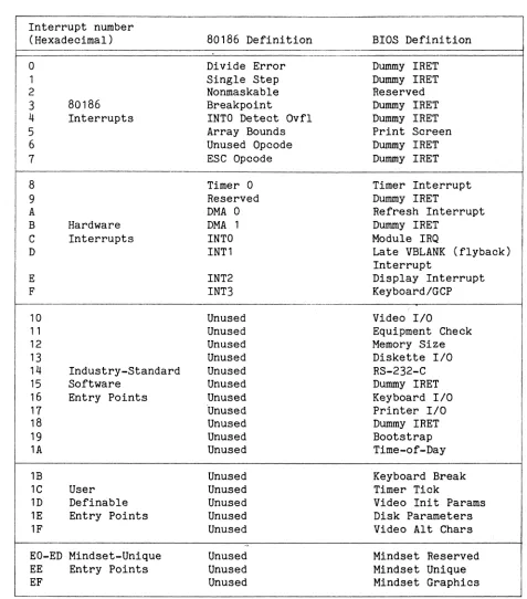
Table 2-1 lists the BIOS interrupts of the Mindset computer system.
Table 2-1: Interrupt Vectors
Interrupt number (Hexadecimal)
o
1 2 3 4 5 6 1 8 9 A B C D E F 10 11 12 13 14 15 16 11 18 19 1A 1B 1C 1D 1E 1F 80186 Interrupts Hardware Interrupts IndustrY-Standard SoftwareEntry Points
User Definable Entry Points
EO-ED Mindset-Unique EE Entry Points EF
80186 Definition Divide Error Single Step Nonmaskable Breakpoint
INTO Detect Ovfl Array Bounds Unused Opcode ESC Opcode Timer 0 Reserved DMA 0 DMA 1 INTO INT1 INT2 INT3 Unused Unused Unused Unused Unused Unused Unused 'Unused Unused Unused Unused Unused Unused Unused Unused Unused Unused Unused Unused
BIOS Definition Dummy IRET Dummy IRET Reserved Dummy IRET Dummy IRET Print Screen Dummy IRET Dummy IRET Timer Interrupt Dummy IRET
Refresh Interrupt Dummy IRET
Module IRQ
Late VBLANK (flyback) Interrupt
Display Interrupt KeyboardlGCP
(
Video 1/0
Equipment Check Memory Size Diskette 1/0
RS-232-C Dummy IRET Keyboard 1/0
Printer I/O Dummy IRET Bootstrap Time-of-Day Keyboard Break Timer Tick
[image:19.612.62.539.137.679.2]HIHDSET-NATIVE ENTRY POINTS
The following two lists present the Miridset-unique ROM BIOS commands offered under interrupts EE hexadecimal and EF hexadecimal. ("Hexadecimal" is abbre-viated to "hex" or "H" in this manual.)
The first list includes the commands under interrupt EEH, which is the entry-point interrupt for the general ROM BIOS functions. The value of register AH selects the specific command.
Command
Write TTY String
Write TTY String with Attributes
Set Display Device
Set Screen Position Get Screen Position Set Cursor
Set Display Features
Set Display Interrupt
Shape
Sync
Value of Decimal 00 01 02 03 04 05 06 07 AH Hex 00 01 02 03 04 05 06 07 Function
Writes a character string to a screen buffer.
Writes a character string with character attributes to a buffer. Sets the display for either a tele-vision or an RGB monitor and reloads the color palette. Also enables or disables color output to a television display.
Sets the screen position within the screen border.
Returns the current position of the screen within the screen border. Sets the shape of the cursor for character modes.
Enables or disables the use of gen-lock for transparent colors, enables or disables interlaced sync display, and enables or disables fixed-phase display.
Command
RT Clock Set Status
RT Clock Get Status
RT Clock Read Time
RT Clock Set Time RT Clock Read Date
RT Clock Set Date RT Clock Read Alarm
RT Clock Set Alarm
RT Clock Set Int
Reserved
ROM/RAM Cart Status
RAM Cart Format
RAM Cart Get Entry
RAM Cart Put Entry
RAM Cart Read
RAM Cart Write
Value of AH Decimal Hex
10 OA
11 OB 12 OC
13 OD
14 OE
15 OF
16 10
17 11
18 12
19 13
20 14
21 15
22 16
23 17
24 18
25 19
Function
Sets or clears the valid/invalid status of the real-time clock. Returns the valid/invalid status of the real-time clock.
Returns the time from the real-time clock.
Sets the time on the real-time clock. Returns the date from the r'eal-time clock.
Sets the date on the real-time clock. Returns the time of the
alarm-interrupt setting from the real-time clock.
Sets the time for the alarm interrupt.
Sets the interrupt pointer for the user-specified alarm-interrupt serv-ice routine.
N/A
Returns the operational data for the cartridge and reads the cartridge wait state specification into the system.
Formats a RAM cartridge to accept information and support a directory. Returns RAM cartridge file entry information from the cartridge directory.
Writes RAM cartridge file entry information to the cartridge directory.
Reads blocks of data from a RAM cartridge file.
Command RAM Cart Delete Block Reserved Reserved Reserved Reserved
Joystick Mouse lID
Get Module ID Table
Set Power Off Set LEDs Print String
Set Sound Mode
Set Sound Register
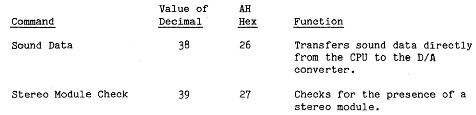
Sound Data
Stereo Module Check
RS-232-C Send Character
RS-232-C Get Character
Value of AH Decimal 26 27 28 29 30 31 32 33 34 35 36 37 38 39 40 41
Hex Function
1A Deletes blocks of data from a RAM cartridge file.
1B N/A
1C N/A 1D N/A
1E N/A
1F Reads the status of two joystickl button, mouse, or other encoder-type controls.
20 Returns a pointer to the table of the IDs of the installed modules.
21 Turns off the power to the system. 22 Turns the system LEDs on or off. 23 Prints a string of characters at the
printer. 24 25 26 27 28 29
Sets the operation mode of the custom sound processor(s).
Sets the registers that control sound proQessor operations.
Transfers sound data directly from the CPU to the system D/A converter. Checks for the presence of a Stereo Sound Module.
Writes a character to the RS-232-C output buffer.
Command
RS-232-C Set Input Buffer
RS-232-C Set Output Buffer
RS-232-C Set Com-munications Control RS-232-C Get Com-munications Control RS-232-C Get Modem Status
RS-232-C Set Com-munications Break Set Auxiliary Output Port Set Module Int
Set System Timer Rate
Get System Timer Rate
Enable/Disable Beeper
Check Beeper Enable
Set Beeper
Value of AH Decimal Hex
44 2C
45 2D
46 2E
47
2F48 30
49 31
50 32
51 33
52
34
53 35
54 36
55 37
56 38
Function
Specifies the RS-232-C input ' buffer.
Specifies the RS-232-C output buffer.
Specifies RS-232-C communications controls and interrupt enables.
Returns RS-232-C communications modem controls and interrupt enables.
Returns information on modem installations.
Sends a break signal over the RS-232-C communications line.
Sets the system auxiliary output port logic state.
Specifies the interrupt pointer for the user-specified module interrupt service routine.
Changes the rate at which the system timer interrupts.
Returns the rate at which the system timer interrupts.
Enables or disables the system beeper.
Indicates whether the beeper is enabled.
The second list presents the commands under interrupt EFH. These commands are the Mindset-unique extended graphics commands. The value of register AH
selects a specific graphics command from the following list.
Command
Set Screen Mode
Get Screen Mode
Set Transfer Mode
Get Transfer Mode
Set Destination Buffer
Get Destination Buffer
Set Write Mask
Get Write Mask BLT Copy
BLT Copy Word
Set Palette
Value of AH Decimal 00 01 02 03 04 05 06 07 08 09 10 Hex 00 01 02 03 04 05 06 07 08 09 OA Function
Selects graphics resolution, number of colors, single or double buffer-ing, and interlaced or non-interlaced operation.
Returns the current screen mode parameters.
Specifies the transparent or opaque mode and the NOT, AND, OR, or
exclusive-OR mode for GCP data transfers.
Returns the current GCP transfer mode parameters.
Specifies the address and size of the BLT destination buffer.
Returns the address and size of the current BLT destination buffer. Specifies a 16-bit write mask that enables selective bit modification during data transfer operations. Returns the 16-bit write mask.
Copies a region of the source buffer to the destination buffer.
Fills rectangular regions of the destination buffer with a user-specified 16-bit fill pattern.
user-Command BLT Polyline
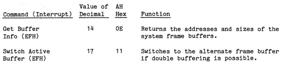
Get Buffer Info
Set Display Int Address
Get Display Int Address
Switch Active Buffer
Set Collision Pattern
Get Collision Pattern
Set Clip Rectangle
Get Clip Rectangle Set Co11ision/C1ip/ Done Detect
Get Co1Iision/Clip/ Done,Detect
GCP Wait
BLT Polygon
Value of AH Decimal 13 14 15 16 17 i8 19 20 21 22 23 24 25 Hex
aD
OE OF 10 11 12 13 14 15 16 17 18 19 FunctionDraws a series of lines of the same color into the destination buffer.
)
Returns the addresses and sizes of the system frame buffers.
Specifies the address of the user-defined display interrupt service routine that the system calls as part of each display interrupt.
Returns the address of the user-defined display interrupt service routine.
Switches to the alternate frame buffer if double buffering is possible.
Specifies the pattern that, when found, indicates a collision. Returns the current collision pattern.
Specifies the clipping bounds for graphics commands.
Returns the current clipping bounds. Sets the collision and clip enable flags and the address for the user-defined collision/c1ip/done-interrupt service routine.
Returns the settings of the colli-sion and clip enable flags and the address for the user-defined
collision/clip/done-interrupt service routine.
Waits until the block-transfer hard-ware completes its current task and then returns the collision/clip status.
Command
BLT Filled Ellipses
BLT Hollow Ellipses
Save GCP
Restore GCP
Fill Dest Buffer
Set Font Pointer
Get Font Pointer
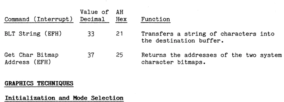
BLT String
Set Param Block Mode
Get Param Block Mode
Get GCP Status
Get Char Bitmap Address
Get BLT Memory Bounds
Value of AH Decimal 26 27 28 29 30 31 32 33 34 35 36 37 38 Hex 1A 1B lC 1D 1E 1F 20 21 22 23 24 25 26 Function
Draws a series of filled ellipses or ellipse sectors into the destination buffer.
Draws a series of hollow ellipses or elliptical arcs into the destination buffer.
Saves the current state of the graphics coprocessor in the user-specified data area.
Restores data previously saved by the Save GCP routine.
Fills the destination buffer with specified data.
Sets a pointer to a user-defined font descriptor block.
Returns the pointer to a user-defined font descriptor block.
Transfers a string of characters into the destination buffer.
Specifies the representation for cer-tain BLT command parameter blocks. Returns the current parameter block representation mode.
Returns the current GCP status word. Returns the addresses of the two system character bitmaps.
The second group of commands covered, in Section 4, are the Mindset-native graphics commands. These commands constitute the powerful graphics capabili-ties of the Mindset computer. The Mindset-unique graphics section describes the functions for both the display processor and the graphics coprocessor. Section 5 in the manual describes the custom sound-processor (CSP) operations and capabilities. The CSP provides a fundamental set of sound-processing options that give you great creative opportunities.
Keyboard operations are covered in Section 6. This section discusses the industry-standard scan codes of the Mindset keyboard and the Mindset-unique keys also provided. In particular, the single-key-operated option is
explained in detail.
The real-time clock is the subject of Section
7.
This section covers the features of the real-time clock and details the corresponding commands. Section 8 covers RAM/ROM cartridge operation. Again, the section discusses the operational features and details the corresponding commands.Mindset-native communications commands are the subject of Section 9. This section enumerates the many commands the Mindset computer provides for versa-tile RS-232-C standard communications and describes the two modem modules and their commands that enable telecommunications.
Section 3
INDUSTRY-COMPATIBLE BIOS FUNCTIONS
OVERVIEW OF COMPATIBILITY AND INCOMPATIBILITY
In the Mindset Personal Computer, access to all hardware and devices occurs through the ROM BIOS; access to the ROM BIOS is by means of software inter-rupts. These software interrupts are generally entry-point compatible with industry-standard software interrupts. This compatibility means that most programs designed for an industry-standard personal computer will run on the . Mindset computer with no special modifications.
The ROM BIOS provides a software interface between user applications and the system hardware. Rather than directly accessing hardware, the user should always use the routines from the ROM BIOS to set up and control the operations of the Mindset computer.
The Mindset computer offers features beyond those of the industry-standard computer. As an applications programmer, you should be aware of the extra features provided by the Mindset computer and how they affect compatibility with industry-standard operations. The remainder of Section 3 describes the compatibilities and incompatibilities between the Mindset and industry-standard personal computers.
MINDSET FEATURES THAT ARE INCOMPATIBLE WITH INDUSTRY STANDARDS
In some areas of operation, the Mindset BIOS routines differ from those of the industry-standard personal computer. These areas include the PRINT SCREEN interrupt command, the video IIO interrupt, the keyboard interrupt, the disk bootstrap interrupt, and the cassette interrupt.
Interrupt 05H is normally the industry-standard PRINT SCREEN command on the Mindset computer. The 80186 central processor chip, however, uses interrupt 05H to signal that an array index is outside of program-specified bounds when checked with the BOUNDS instruction.
The industry-standard video I/O interrupt (10H) is supported in both the industry-standard character modes and the Mindset-native graphics modes, but with the following differences:
• In the industry-standard character modes, the Mindset computer provides half the number of character pages (2 in 80-column mode and 4 in 40-column mode).
• Where double buffering is possible in Mindset graphics modes, the page number (O or 1) is required for the character-read- and character-write-type commands.
• In Mindset graphics interlaced modes, characters are 16 scan lines high, not 8.
• The WRITE TELETYPE command of the Mindset computer, unlike that of the industry-standard personal computer, actually does use the page number passed in BH. The industry-standard personal computer restricts the out-put of this command to the active page.
Other industry-standard reserved interrupts handled in a nonstandard way by the Mindset computer are the keyboard interrupt (09H), the disk bootstrap interrupt (19H), interrupts OAH through ODH, and the cassette BASIC interrupt
18H.
For the industry-standard computer, interrupt 09H is the keyboard interrupt. The Mindset computer reserves interrupt 09H for future use.
Interrupt 19H, the disk bootstrap interrupt for the industry-standard personal computer, is the cartridge and disk bootstrap interrupt for the Mindset compu-ter. The Mindset computer may try to boot from a ROM or ROM/RAM cartridge before it tries to boot from a diskette, depending on the priorities set on the system configuration screen.
Interrupts OAH through ODH are reserved (but not dedicated) by the BIOS of the industry-standard personal computer. The Mindset computer uses OAH through ODH for the 80186 hardware functions DMA 0, DMA 1, INT 0, and INT 1, respec-tively, as listed in Table 2-1.
The BIOS of the industry-standard personal computer specifies that interrupt 18H is for cassette I/O, but the BIOS of the Mindset computer replaces inter-rupt 18H with a dummy IRET instruction.
CHARACTER MODE OPERATION
Character mode operation of the Mindset computer is compatible with that of the industry-standard color/graphics adapter, with three exceptions:
1. The Mindset computer provides 2 pages of text storage for aO-column mode and 4 pages for 40-column mode. The industry standard is 4 pages and a pages, respectively. See Section 4, "Mindset-Native Graphics Operation", for screen format details.
2. The Mindset computer enables the user to redefine the cursor shape. The industry standard is a variable-height block cursor the width of one char-acter. See Section 4 for a description of the cursor shape definition command.
3.
The character modes of the Mindset computer provide two colors instead of the eight colors and two intensities of the industry-standard personal computer. See Section 4 for screen format details.In character modes, there is a buffer of several pages of ASCII characters with attributes. There are 4 pages in 40-column modes, and 2 pages in aO-column modes. The buffer of ASCII characters with attributes is used during early VBLANK (vertical flyback) time to draw the display buffer.
Each display page has a cursor position. The cursor for the active page (the page currently displayed) is drawn on the screen. The cursor for any other page is the location at which characters are put or read; it is not displayed. Page numbers start at
a
for the first page.Rows begin at
a
for the top row on the screen, and go to 24. ColumnS begin ata
for the left-most column on the screen, and go to either79
or39.
The format of the display page buffers in industry-standard character modes is an array of words. Each word contains an ASCII character code as the lower byte and an attribute as the upper byte. The attribute specifies
blink/no-blink and colors for the character and background. The format of the attribute byte is:
Bit(s) 7
Definition
The following list shows how the attribute specifications.are implemented on the Mindset computer:
Attribute Blink set (= 1) Foreground
=
black, Background=
anything Foreground=
color, Background=
anything Intensity set (= 1). Display on Mindset Computer Character blinks
Character is black, background is white Character is white, background is black Not implemented
Only two colors are displayed, so reverse video and blink are the only attri-butes shown on the screen. To display other colors, use the Mindset SET PALETTE command to redefine a color to be displayed instead of black (color
o
in the frame buffer) and white (color 1 in the frame buffer).GRAPHICS MODE OPERATION
The Mindset computer supports the industry-standard 320- and 640-pixel-wide graphics modes. In addition, the Mindset computer offers a number of graphics features that go far beyond the industry standard. The extended capabilities of Mindset's display processor/graphics coprocessor combination include the following:
• Flexible graphics modes:
- A 16-color, 320-pixel-wide display mode - A 4-color, 640-pixel-wide display mode
- Double-buffered modes with 2 or 4 colors for 320 pixels or 2 colors for 640 pixels
- Interlaced modes for doubled vertical resolution
• An interrupt to synchronize program activity with the screen refresh • A screen image that the user can relocate within the border area
• The ability to synchronize with and mix display with an external video input
• Support for the industry-standard personal computer 320- and 640-pixel-wide graphics modes
Characters can be drawn in all graphics modes. In modes where there is only one display page, the Mindset computer ignores page parameters related to industry-standard video commands. The cursor position determines character positioning. For character IIO routines in graphics modes, row means a char-acter row (8 pixel lines) and column means a charchar-acter column (8 pixels wide). For pixel referencing, columns begin at 0 for the left-most column and go to either 639 or 319. Rows begin at 0 and end at 199 for all industry-standard compatible modes; only in Mindset 400-scan-line modes does the row number go to 399. The system changes any illegal value for a pixel row or column to the maximum allowable.
In industry-standard graphics modes, the frame buffer picture is stored with even scan lines and odd' scan lines separated. In other words, all the even scan lines (0,2,4, ••• ) are stored first, and then all the odd scan lines
(1,3,5, ••• ). In Mindset-native graphics modes, the frame buffer is organized the same way it appears on the screen, starting with scan line 0 and continu-ing through scan line 199 or 399. Graphics operation with the Mindset com-puter is described in detail in Section 4.
DESCRIPTIONS OF INDUSTRY-COMPATIBLE INTERRUPTS
The industry-compatible interrupts are: Interrupt Name Interrupt Number
Print Screen 05H
Video IIO 10H
Equipment check 11H
Memory size check 12H
Disk IIO 13H
RS-232-C IIO 14H
Keyboard IIO 16H
Printer IIO 17H
Cassette I/O* 18H
System bootstrap 19H
Time-of-day 1AH
Keyboard break 1BH
Timer tick 1CH
Video parameters 1DH
The following sections describe each interrupt.
Print Screen -- Interrupt O5H
The Mindset print screen interrupt is identical to the industry-standard print screen interrupt. Invoking this interrupt causes the contents of the screen to be sent to the printer.
In character modes, the print screen interrupt sends the entire screen of characters to the printer.
In graphics modes, the print screen interrupt sends only characters that are drawn in some foreground color to the printer. This interrupt sends any other graphics or reverse-video characters to the printer as spaces.
Video I/O -- Interrupt 10H
The Mindset video I/O interrupt is a software interrupt entry point identical in function to the industry-standard video I/O entry point. To apply this entry pOint, the user places a function code in register AH and other param-eters in other registers as described subsequently, and calls interrupt 10H. Except where noted otherwise, all functions described below work the same in Mindset display modes as they do in industry-standard modes.
The functions provided by the video I/O interrupt are: Value of AH
Command Decimal
Set Mode 00
Set Cursor Type 01 Set Cursor Position 02 Read Cursor Position 03
"
Reserved 04
Select Active 05
Display Page
Scroll Active Page 06 Up
Scroll Active Page 07 Down
Read Attribute/ 08 Character Hex 00 01 02 03 04 05 06 07 08 Function
Specifies the video display mode.
Specifies the appearance of the cursor. Specifies the cursor location.
Returns the current cursor position. N/A
Specifies the page to be displayed.
Specifies upward movement of a part of the displayed page.
Specifies downward movement of a part of the displayed page.
Value of AH
Command Decimal Hex
Write Attribute/ 09 09 Character
Write Character 10 OA Only
Set Color Palette 11 OB
Write Dot 12 OC
Read Dot 13 OD
Write Teletype 14 OE
Current Video State 15 OF
Function
Writes the specified attribute/ character to the current cursor position.
Writes a character only to the current cursor position.
Specifies the color palette for use in industry-standard display modes.
Writes a single pixel with a specified color at a specified position.
Returns the color of a specified pixel. Writes a teletype (TTY) character to the display.
Returns the current mode, number of character columns, and active display page.
All registers except those used to return values remain unchanged after a call.
SET MODE -- Int. 10H, (AH)
=
OOHFunction: Specifies the video display mode.
Description: The SET MODE video IIO command selects one of eight display modes for use.
Input
Parameters:
Output Parameters:
In graphics modes,· the display processor initializes the display buffer by filling it with Os. In character modes, the display processor fills the display buffer with spaces and attribute value 7 (white on black), sets the display page to 0, and ini-tializes the cursor to lines 6 through 7 (see the SET CURSOR TYPE function, described next).
(AL)
None.
is the mode selected. The modes are:
Character Modes
Graphics Modes
CRT mode
Mode
0
1
2 3 4 5 6
7
Color or Black-and-Specification White (B&W)
40 x 25 B&W
40 x 25 Color (2 colors) 80 x 25 B&W
80 x 25 Color (2 colors)
320 x 200 Color (4 colors) 320 x 200 B&W
640 x 200 B&W
SET CURSOR TYPE -- Int. 10H, (AH)
=
01HFunction: Specifies the height of the cursor.
Description: The SET CURSOR TYPE video I/O command specifies the appearance of the cursor, which appears in character modes only. The cur-sor has a fixed width (one character wide) but variable begin-ning and end lines that are set with this command. For example, if you place the start and end lines at the same position, the cursor appears as a blinking horizontal line. If you put the start line at 0 and set the end line at
7,
the cursor appears as a blinking box the height and width of a standard video char-acter. (Line 0 is the top line and line 7 is the bottom line of the character position.)Input
Parameters:
Output Parameters:
The cursor blink function cannot be altered.
The system saves the cursor parameters in the BIOS data area. The parameters can be returned using the CURRENT VIDEO STATE or READ CURSOR POSITION command.
(CH) is the cursor start line, 0 to 15 decimal. Using a number greater than 7 results in no cursor display. (CL) is the cursor end line, 0 to 15 decimal. Using a
num-ber greater than 7 results in no cursor display.
SET CURSOR POSITION -- Int. 10H, (AH)
=
02HFunction: Specifies the cursor location.
Description: The SET CURSOR POSITION video 1/0 command specifies the row~ column, and page number for the cursor. A (row, column) value of (0,0) indicates the upper left corner.
Input
Parameters:
Output Parameters:
(BH) is the page number. In all modes, the display proces-sor masks (BH) to a legal page value.
(DH) is the row number, automatically limited by the SET CURSOR POSITION routine to the maximum for the current mode.
(DL) is the column number, automatically limited by the SET CURSOR POSITION routine to the maximum for the current mode.
READ CURSOR POSITION -- Int. 10H, (AH)
=
03HFunction: Returns the current cursor position.
Description: The READ CURSOR POSITION video I/O command returns the current row number, column number, start line, and end line for the cursor.
Input
Parameters:
Output Parameters:
(BH)
(CH)
is the page number, ignored if currently in a mode with only one page. In all modes, the display proces-sor masks (BH) to a legal value.
is the cursor start line. (CL) is the cursor end line.
SELECT ACTIVE DISPLAY PAGE -- Int. 10H, (AH)
=
05HFunction: Specifies the page to be displayed.
Description: The SELECT ACTIVE DISPLAY PAGE video liD command selects one of up to 2 pages (modes 2 and 3) or 4 pages (modes 0 and 1) for
display in character modes.
Input Parameter:
Output Parameters:
In Mindset-native graphics modes that allow double buffering, the SELECT ACTIVE DISPLAY PAGE command does not have the effect of the SWITCH ACTIVE BUFFER command--it cannot switch the active buffer for display. The SELECT ACTIVE DISPLAY PAGE routine does, however, select the active page for other video liD com-mands such as SCROLL ACTIVE PAGE UP, WRITE DOT, and READ DOT.
(AL)
None.
is the new page number: 0 or 1 for Mindset-native graphics modes, 0 to 3 for industry-standard modes
o
and 1, or 0 to 1 for industry-standard modes 2 and3.
(AL) has no effect in graphics modes with only 1 page. The SELECT ACTIVE DISPLAY PAGE routine masksSCROLL ACTIVE PAGE UP -- Int. 10H,(AH)
=
06HFunction: Specifies upward movement of a part of the displayed page.
Description: The SCROLL ACTIVE PAGE UP video IIO command specifies the number of lines, the upper left corner, the lower right corner, and the blank line attribute for use in the upward scroll procedure.
Input
Parameters:
Output Parameters:
The upward scroll moves the specified number of lines up within the specified rectangular area in the active page and fills the area at the bottom with spaces having a specified attribute (in character modes), or with a specified fill byte (in graphics modes).
(AL) is the number of lines to be moved at the top of the rectangular region (window) specified in (CH, CL) and
(DH, DL) below, with blank line replacements at the bottom. A value of 0 for (AL) causes the active win-dow to be filled with blank lines.
(BH) is the attribute (in character modes) or fill byte (in graphics modes) used to fill the blank lines that enter at the bottom of the scroll window.
(CH) is the row of the upper left corner of the scroll window.
(CL) is the column of the upper left corner of the scroll window.
(DH) is the row of the lower right corner of the scroll window.
(DL) is the column of the lower right corner of the scroll window.
SCROLL ACTIVE PAGE DOWN -- Int. 10H, (AH)
= 07H
Function: Specifies a downward movement of a part of the displayed page.
Description: The SCROLL ACTIVE PAGE DOWN. video 1/0 command specifies the num-ber of lines, the upper left corner, the lower right corner, and the blank line attribute for use in the downward scroll
procedure.
Input
Parameters:
Output Parameters:
The downward scroll moves the specified number of lines down within the specified rectangular area in the active page and fills the area at the top with spaces having a specified attri-bute (in character modes), or with a specified fill byte (in graphics modes).
(AL) is the number of lines to be moved at the bottom of the rectangular region (window) specified in (CH, CL) and (DH, DL) below, with blank line replacements at the top. A value of 0 for (AL) causes the active win-dow to be blanked.
(BH) is the attribute (in character modes) or fill byte (in graphics modes) used to fill the blank lines that enter at the top of the scroll window.
(CH) is the row of the upper left corner of the scroll win-dow.
(CL) is the column of the upper left corner of the scroll window.
(DH) is the row of the lower right corner of the scroll window.
(DL) is the column of the lower right corner of the scroll window.
READ ATTRIBUTE/CHARACTER -- Int. 10H, (AH)
=
08HFunction: Returns the attribute/character at the current cursor position. Description: In character modes, the READ ATTRIBUTE/CHARACTER video I/O
com-mand returns the character and attribute, corresponding to the current cursor position, which are in the ASCII/attribute buf-fer. Input for this command is the page number of the current display.
Input Parameter:
Output Parameter:
In graphics modes, the READ ATTRIBUTE/CHARACTER command compares the contents of the graphics buffer to the 8 x 8 pixel character representations stored in either BIOS ROM or user-defined bit-maps. The character may consist of any combination of fore-ground colors on a backfore-ground color. The first character that matches the contents of the graphics buffer is returned in AL. The character search starts with character O.
The READ ATTRIBUTE/CHARACTER routine returns no attribute in graphics modes.
(BH)
(AH)
is the display page number (valid for character modes and some Mindset-native graphics modes).
is the attribute of the character at the current cur-sor position (valid for character modes and some Mindset-native graphics modes).
(AL) is the character at the current cursor position (or
WRITE ATTRIBUTE/CHARACTER -- Int. 10H, (AH)
=
09HFunction: Writes an attribute/character to the current cursor position. Description: In character modes, the WRITE ATTRIBUTE/CHARACTER video I/O
com-mand puts the specified attribute and character into the ASCII/attribute buffer.
Input
Parameters:
Output Parameters:
In graphics modes, BL specifies the color. If bit 7 of BL is set, the character will be exclusive-ORed into the frame buffer. The WRITE ATTRIBUTE/CHARACTER command draws the character(s) from an 8 x 8 pixel representation stored in BIOS ROM, or from a user-defined alternate character set if the character has a numerical equivalent greater than 127.
In 400-pixel line graphics modes, the character is drawn as 8 pixels wide by 16 pixels high so that it looks the same as the characters in other modes.
(AL) is the character this command is to write.
(BH) is the display page number (valid for character modes and some Mindset-native graphics modes).
(BL) is the attribute of the character to be written (in character modes) or the color of the character (in graphics modes). If bit 7 of BL is 1 in graphics modes, then the color value specified is exclusive-ORed with the current color of the cursor position. (CX) is the number of times the character is to be written.
(All characters must remain on the same row.)
WRITE CHARACTER ONLY -- Int. 10H, (AH)
=
OAHFunction: Writes a character to the current cursor position.
Description: The WRITE CHARACTER ONLY video I/O command displays the speci-fied character at the current cursor position.
Input
Parameters:
Output Parameters:
In graphics modes, the WRITE CHARACTER ONLY command is equiva-lent to the WRITE ATTRIBUTE/CHARACTER command. BL must specify a color for the character.
In character modes, the WRITE CHARACTER ONLY command replaces the character only, leaving the corresponding attribute
unchanged.
(AL) is the character this command is to write.
(BH) is the display page number (valid for character modes and some Mindset-native graphics modes).
(BL) is the color of the character (for graphics modes only). If bit 7 of BL is 1, then the color value specified is exclusive-ORed with the current color of the cursor position.
(CX) is the number of times the character is to be written. (All characters must remain on the same row.)
Function:
SET COLOR PALETTE -- Int. 10H, (AH)
=
OBHSpecifies the color palette for use in industry-standard display modes.
Description: The SET COLOR PALETTE video 1/0 command specifies the fore-ground, backfore-ground, and/or border colors, or the color palette, for use in industry-standard graphics and character modes. The result of the SET COLOR PALETTE depends on the values placed in BH and BL, as described below. This command is not flexible or useful as the Mindset-unique SET PALETTE command; it only
provides industry-standard compatibility. Input
Parameters:
Output Parameters:
(BH) is the identification (ID) number of the palette color to be set. For graphics modes, an ID number of 0 indicates the background and border color and an ID number of 1 selects a foreground color. In character modes, an ID number of 0 indicates the border color
(an ID number of 1 is not used).
(BL) is the color value fOF the foreground, background, and/or border as determined by the identification num-ber in BH and the current display mode. The color value placed in BL when (BH) = 0 must follow the intensity/red/green/blue format described under Color Palette Control in Section 4, "Mindset-Native Graphics Operation". When (BH)
=
1, (BL) specifies one of two color palettes.None.
(BL) specifies the foreground, background, and/or bor-der colors or the foreground color palette as follows: When (BH)
=
0, (BL) specifies the border color for character modes 0, 1, 2, and3,
the background and border color for industry-standard graphics modes 4 and 5, and the foreground color for industry-standard graphics modes 6. When (BH)=
1, (BL) specifies the foreground color palette for industry-standard graph-ics modes4
and 5 only. In this case, (BL)=
0 speci-fies the red/green/yellow palette and (BL)=
1WRITE DOT -- Int. 10H, (AH)
=
OCHFunction: Writes a single pixel with a specified color at a specified position.
Description: The WRITE DOT video I/O command displays a dot (single pixel) with the specified color at the specified location on the active page.
Input
Parameters:
Output Parameters:
(AL) is the desired color value. If bit 7 of AL is a 1, then the color value is exclusive-ORed with the cur-rent color at the pixel specified by (CX) and (OX). (CX) is the column number.
(DX) is the row number.
READ DOT -- Int. 10H, (AH)
=
ODH-Function: Returns the color of a specified pixel.
Description: The READ DOT video I/O command returns the color value of a pixel specified by row and column numbers. This command has no effect in character modes.
Input
Parameters: (eX) is the column number. (OX) is the row number. Output
WRITE TELETYPE -- Int. 10H, (AH)
=
OEHFunction: Writes a teletype (TTY) character to the display.
Description: The WRITE TELETYPE video 110 command writes a specified char-acter to a specified display page using the WRI~E CHARACTER ONLY routine and then updates the cursor position.
Input
Parameters:
If the cursor position was at the right-most column on the page, the WRITE TELETYPE routine sends the character (and the cursor position) to the next line.
The WRITE TELETYPE command implements four control characters (carriage return, line feed, bell, and backspace) as follows: 1. A carriage return returns the cursor to column 0 of the
cur-rent line.
2. A line feed sends the cursor to the next line, remaining in the current column, and scrolls the entire display page up if necessary.
3.
A bell causes the beeper to beep if the beeper is enabled and causes the custom sound-processor (CSP) to emit a tone as specified by the CSP sound registers.4. A backspace moves the cursor back one column with no erase of the character, unless the cursor is already at column O. In column 0, no backspacing is possible.
If the character is a line feed, and the cursor is already on the last line of the page, the routine scrolls the page up one line and fills the new line with blanks (in character modes) or with zeroes (in graphics modes).
As implemented on industry-standard personal computers, this call is limited to operating on the active page. On the Mindset computer, the call works for any valid page number passed in BH.
CAL) is the character to be written.
CURRENT VIDEO STATE -- Int. 10H, (AH)
=
OFHFunction: Returns the status of the current video state.
Description: The CURRENT VIDEO STATE video I/O command