Headquarters, Department of the Army
ÿþýüûúùøü÷
ÿþýüûúùøü÷
ÿþýüûúùøü÷
No. 3-19.30
PREFACE...vi
Chapter 1 PHYSICAL-SECURITY CHALLENGES... 1-1 Overview ... 1-1 Automated Information Systems... 1-1 OPSEC and the Threat ... 1-3
Chapter 2 THE SYSTEMS APPROACH... 2-1 Protective Systems ... 2-1 Systems Development ... 2-2 The Integrated Protective System ... 2-5 Security Threats ... 2-6
Chapter 3 DESIGN APPROACH... 3-1 Design Strategies... 3-1 Protective Measures ... 3-1 Vehicle Bombs ... 3-2 Exterior Attack... 3-10 Standoff Weapons ... 3-13 Ballistics ... 3-16 Forced Entry... 3-17 Covert Entry and Insider Compromise... 3-19 Surveillance and Eavesdropping ... 3-20 Mail and Supply Bombs ... 3-22 Chemical and Biological Contamination ... 3-24
Chapter 4 PROTECTIVE BARRIERS... 4-1 Overview ... 4-1 Fencing ... 4-2 Utility Openings ... 4-5 Other Perimeter Barriers... 4-5 Security Towers ... 4-5 Installation Entrances... 4-6 Warning Signs... 4-8 Other Signs ... 4-8 Installation Perimeter Roads and Clear Zones ... 4-8 Arms-Facility Structural Standards ... 4-9
Headquarters Department of the Army Washington, DC, 8 January 2001
PHYSICAL SECURITY
Contents
Distribution Restriction: Approved for public release; distribution is unlimited. *This publication supersedes FM 19-30, 1 March 1979.
Page Chapter 5 PHYSICAL-SECURITY LIGHTING ... 5-1
Overview ... 5-1 Commander’s Responsibility... 5-1 Planning Considerations ... 5-2 Principles of Security Lighting ... 5-3 Types of Lighting ... 5-4 Wiring Systems ... 5-5 Maintenance... 5-6
Chapter 6 ELECTRONIC SECURITY SYSTEMS ... 6-1
Overview ... 6-1 ESS Design Considerations ... 6-2 Interior ESS Considerations ... 6-7 Exterior ESS Considerations... 6-8 ESS Alarm-Annunciation System... 6-12 ESS Software ... 6-17 Interior Intrusion-Detection Sensors... 6-18 Exterior Intrusion-Detection Sensors ... 6-29 Electronic Entry Control ... 6-39 Application Guidelines... 6-42 Performance Criteria ... 6-43 Data Transmission ... 6-44 CCTV for Alarm Assessment and Surveillance... 6-45
Chapter 7 ACCESS CONTROL ... 7-1
Designated Restricted Areas ... 7-1 Employee Screening ... 7-4 Identification System ... 7-4 Duress Code ... 7-10 Access-Control Rosters ... 7-10 Methods of Control... 7-10 Security Controls of Packages, Personal Property, and Vehicles... 7-11 Tactical-Environment Considerations ... 7-12
Chapter 8 LOCK AND KEY SYSTEMS... 8-1
Installation and Maintenance ... 8-1 Types of Locking Devices ... 8-1
Chapter 9 SECURITY FORCES ... 9-1
Page
Communications ... 9-9 Miscellaneous Equipment ... 9-9 Military Working Dogs ... 9-10 Summary ... 9-10
Chapter 10 IN-TRANSIT SECURITY... 10-1
In-Port Cargo... 10-1 Rail Cargo ... 10-4 Pipeline Cargo... 10-6 Convoy Movement ... 10-7
Chapter 11 INSPECTIONS AND SURVEYS ... 11-1
Inspections ... 11-1 Surveys ... 11-2
Appendix A METRIC CONVERSION CHART ... A-1
Appendix B SAMPLE INSTALLATION CRIME-PREVENTION HANDBOOK... B-1 Section I — Installation Crime-Prevention Programs ...B-1
Crime-Prevention Working Groups ... B-1 Crime-Prevention Officers ... B-2 Crime-Prevention Program Development ...B-2 Training ...B-5 Civilian Crime-Prevention Organizations...B-5
Section II — Criminal Analysis ...B-5
Sources of Information ...B-6 Individual Criminal Analysis ... B-9 Criminal-Analysis Procedures ... B-15 Criminal-Analysis Summary ... B-17
Section III — Command and Law-Enforcement Countermeasures ... B-17
Crime Hot Lines ... B-17 Crime Prevention Through Environmental Design ... B-18 Specialized Patrol Tactics and Surveillance ...B-25 Publicity Campaigns...B-30 Residential-Security Surveys ...B-31 Juvenile Crime Prevention ...B-34 Fraud ...B-47 Internal Theft ...B-52 Pilferage ...B-53
Section IV — Army Property at the Local Level ...B-61
Motor Vehicles ...B-61 Consumer Outlets ...B-63 Arson ...B-66
Section V — Community Crime-Prevention Programs...B-67
Neighborhood Watch Program...B-67 Operation ID ...B-71 Neighborhood Walks ...B-74 Vigilantism ...B-75 Mobile Patrols ...B-76 Project Lock ...B-76
Page
Crime-Prevention Programs...B-79 Crime Rates ...B-83 Measures of Effectiveness ...B-84 Internal Measures ...B-85
Appendix C INTELLIGENCE, COUNTERINTELLIGENCE, AND THREAT ANALYSIS ...C-1
Information Sources ...C-1 Responsibilities of US Government Lead Agencies...C-2 Information Requirements...C-4 Threat Analysis and Assessment ...C-5 Determination of the Threat Level...C-6
Appendix D CRISIS-MANAGEMENT PLAN ...D-1
Appendix E OFFICE SECURITY MEASURES ...E-1
Physical-Security Survey ...E-1 Security-Engineering Assessment ...E-1 Technical Assessment of Responses ...E-2 Physical-Security Enhancement Measures...E-2
Appendix F PHYSICAL-SECURITY PLAN ... F-1
Annexes ... F-6 Tactical-Environment Considerations ... F-7
Appendix G PERSONAL-PROTECTION MEASURES ... G-1
Personal Protection ... G-1 Working Environment ... G-2 Home Environment ... G-4
Appendix H BOMBS ...H-1
General ...H-1 Concealing Bombs ...H-1 Damage and Casualty Mechanisms ...H-1 Telephonic Threats ...H-3 Evacuation Drills ...H-3 Searching for a Suspected IED...H-6
Appendix I EXECUTIVE PROTECTION ... I-1
Supplemental Security Measures ... I-1 Executive Protection Goals ... I-1 Residential Security Measures... I-2 Transportation Measures ... I-4 Individual Protective Measures ... I-7 Combating-Terrorism Training for Executives... I-10 Travel to Potential Physical-Threat Risk Areas ... I-10 Protective Security Details ... I-10 Executive-Protection System Integration ... I-12
Appendix J RESOURCE MANAGEMENT... J-1
Page
Projected Requirements... J-1 Obligation Plan ... J-1 Types of Appropriations ... J-2
Appendix K VULNERABILITY ASSESSMENT...K-1
Assessment Considerations...K-1 THREATCON Levels ...K-2 Assessing Vulnerability ...K-3
GLOSSARY ... Glossary-1
BIBLIOGRAPHY... Bibliography-1
This field manual (FM) sets forth guidance for all personnel responsible for physical security. It is the basic reference for training security personnel. It is intended to be a “one-stop” physical-security source for the Department of Defense (DOD), the Department of the Army (DA), and other proponents and agencies of physical security.
Prevention and protection are the two primary concerns of physical security. Both serve the security interests of people, equipment, and property. These interests must be supported at all staff and command levels; and this support must be unified in joint, multinational, and interagency operations.
Support to joint, multinational, and interagency operations relies on the fact that the Army will not conduct operations alone. Additionally, force-projection operations conducted by the military will involve the integration of war-fighting capabilities with stability and support operations. This manual’s primary focus is the articulation of a balanced understanding of physical security for joint, multinational, and interagency operations throughout the environments of peacetime, conflict, and war (whether in the continental United States [CONUS] or outside the continental United States [OCONUS]).
Physical security must integrate the various capabilities of joint, multinational, and interagency operations in pursuit of a seamless connection between the strategic, operational, and tactical levels of war. Physical security must also address an expanded range of threats that embraces not only traditional threat components of war, but also nontraditional threats generated by guerrillas, terrorists, criminals, and natural or man-made disasters. In addition, physical security must address the concept of Homeland Defense due to the aforementioned threats.
Homeland Defense is the military’s role in the United States (US) government’s principal task of protecting its territory and citizens. This is accomplished by joint, interagency, and multijurisdictional organizations. Homeland Defense includes—
• Supporting domestic authorities for crisis and consequence management with regard to weapons of mass destruction (WMD).
• Protecting national-security assets (such as installations) and deploying forces and ensuring the availability, integrity, and adequacy of other critical assets.
• Deterring and defending against strategic attacks while maintaining freedom of action through antiterrorism and force-protection operations.
With this in mind, it is essential to address the five pillars of force protection—combating terrorism, physical security, personal security, law enforcement, and operations security (OPSEC). Physical security is a central component of force protection and provides an integrated venue to express support for operations. Physical security is a primary-leader task and an inherent part of all operations to protect soldiers, family members, civilians, and resources. This function directly supports the Army’s universal task list.
educated in joint, multinational, and interagency operations; and have the ability to perform physical-security functions in support of full-dimension operations.
Appendix A contains an English-to-metric measurement conversion chart. Appendix B is a sample installation crime-prevention handbook. This handbook is designed to assist commanders in developing crime-prevention programs for their installation and units.
The proponent of this publication is HQ TRADOC. Send comments and recommendations on DA Form 2028 directly to Commandant, US Army Military Police School (USAMPS), ATTN: ATSJ-MP-TD, Directorate of Training, 401 Engineer Loop, Suite 2060, Fort Leonard Wood, Missouri 65473-8926.
Physical-Security Challenges
Physical security is defined as that part of security concerned with
physical m easures designed to safeguard personnel; to prev ent
unauthorized access to equipment, installations, material, and documents;
and to safeguard against espionage, sabotage, damage, and theft. As such,
all military operations face new and complex physical-security challenges
across the full spectrum of operations. Challenges relative to physical
security include the control of populations, information dominance,
multinational and interagency connectivity, antiterrorism, and the use of
physical-security assets as a versatile force multiplier.
OVERVIEW
1-1. Reductions in manpower and funding are critical challenges to physical security. Manpower for supporting physical-security activities is reduced through deployments and cutbacks. The rapid evolution of physical-security-equipment technology also lends to physical-security challenges, which are exponentially multiplied by the introduction of the information age.
1-2. Physical-security challenges must be understood, and measures must be taken to minimize them to enhance force protection. Leaders must create order when coming upon a situation; and when they depart, some semblance of that order must remain. They must be aware of the human-dimension factors and ensure that their soldiers do not become complacent. It was human error rather than modern technology that took lives in the bombings of the African embassy. Warning was given, but not heeded. Complacency became a physical-security challenge.
AUTOMATED INFORMATION SYSTEMS
1-3. Success on past battlefields has resulted not so much from technological advances, but from innovative ways of considering and combining available and new technologies as they apply to war fighting. Some of these technologies dealt with disseminating and processing information. For example, the telegraph, the telephone, the radio, and now the computer have redefined the fire-support paradigm.
1-5. The threat to AISs and information systems security (ISS) involves deliberate, overt, and covert acts. This includes the physical threat to tangible property, such as the theft or destruction of computer hardware. Also included is the threat of electronic, electromagnetic-pulse, radio-frequency (RF), or computer-based attacks on the information or communications components that control or make up critical Army command and control (C2) infrastructures. In most cases, the threat’s target is the information itself rather than the system that transmits it. The threat comes from a range of sources, including the following:
• Unauthorized users (such as hackers) are the main source of today’s attacks, primarily against computer-based systems. The threat they pose to AIS networks and mainframe computers is growing.
• Insiders are those individuals with legitimate access to an AIS. They pose the most difficult threat to defend against. Whether recruited or self-motivated, the AIS insider has access to systems normally protected by ISS against an attack.
• Terrorists once had to operate in the immediate vicinity of a target to gain access to or collect intelligence on that target. The proximity to the target risked exposure and detection. Today, a terrorist can accomplish most target selection, intelligence collection, and preoperational planning by gaining access through a computer network. He can increase his probability of success by using computer systems to reduce his “time on target.” Terrorist access to an AIS also increases the threat of critical-data destruction or manipulation. Although his presence would be virtual, the potential for damage to Army C2 systems could be equal to or greater than that achieved by physical intrusion, especially when used as a force multiplier in conjunction with a traditional terrorist attack. Therefore, while traditional preventive measures are still needed to protect unwanted access to information, the information age has added additional concerns for the commander and new opportunities for those with hostile intent.
• Non-state- and state-sponsored groups provide additional challenges. In many cases, it is difficult to confirm state sponsorship of threat activity against an AIS, no matter how apparent the affiliation might seem. Activists of all persuasions are increasingly taking advantage of information-age technology. Neither AISs nor ISS are immune from an adversary’s interest in exploiting US military information systems or disrupting communication infrastructures. The availability of low-cost technology and the proliferation of an AIS increase the risk to the Army by potential adversaries.
• Political and religious groups are other potential adversaries to AISs and ISS. The world’s political climate is diverse and complicated. It embraces traditional mainstream political values, as well as radical religious fundamentalism and political extremism. When political or religious viewpoints also incorporate anti-US sentiment, US information infrastructures (including AISs) are increasingly at risk of penetration or exploitation by these potential adversaries.
1-6. When considering an AIS, physical security is more than just safeguarding the equipment. It includes the following elements:
• Software is marked for each system and secured when not in use. • Initial logon is password-protected (at a minimum).
• Passwords are a minimum of eight characters, using a mixture of letters and numerals.
• Access to an AIS is allowed only to authorized and cleared personnel (per AR 380-19).
1-7. Classified material is entered and transmitted only on approved devices with the following considerations:
• Approved classified devices are operated in a secured environment. • Classified devices are secured in appropriate containers when not in
use.
• Secure telephone unit–III (STU-III) keys are secured in an appropriate safe when not in use (as outlined in AR 380-19).
1-8. Additional information regarding AISs can be found in ARs 380-5 and 380-19. Required training of personnel working with an AIS is located in AR 380-19.
OPSEC AND THE THREAT
1-9. OPSEC is a process of identifying critical information and subsequently analyzing friendly actions attendant to military operations and other activities. The threat is identified using the factors of mission, enemy, terrain, troops, time available, and civilian considerations (METT-TC). The threat defines the physical-security challenges. Implementing physical-security measures supports OPSEC. Providing soundproof rooms for conducting briefings is a simple but invaluable measure.
1-10. Another issue to consider when evaluating physical-security challenges is what actions to take in case of political implications interfering with physical-security measures. In the devastating event at Khobar Towers, a warning was given but not everyone received it. It took too long to evacuate the building after the warning was issued because a cohesive plan was not in place.
The Systems Approach
Commanders must ensure that appropriate physical-security measures are
taken to minimize the loss of personnel, supplies, equipment, and material
through both human and natural threats. Commanders commonly exercise
those protective responsibilities through the provost marshal (PM) and/or
physical-security officer and the force-protection officer. The force-protection
officer must coordinate with several different agencies to complete his
mission. For example, the Army’s Intelligence and Counterintelligence
Program (see Appendix C) provides information that will be used to
complete the unit’s crisis-management plan (see Appendix D).
PROTECTIVE SYSTEMS
2-1. The approach to developing protective measures for assets should be based on a systematic process resulting in an integrated protective system. The protective system focuses on protecting specific assets against well-defined threats to acceptable levels of protection. The system is organized in-depth and contains mutually supporting elements coordinated to prevent gaps or overlaps in responsibilities and performance.
2-2. Effective protective systems integrate the following mutually supporting elements:
• Physical protective measures, including barriers, lighting, and electronic security systems (ESSs).
• Procedural security measures, including procedures in place before an incident and those employed in response to an incident. (These include procedures employed by asset owners and those applied by and governing the actions of guards.)
• Terrorism counteraction measures that protect assets against terrorist attacks.
2-3. The following determinations are made when considering system-development procedures:
• The resources available. • The assets to be protected. • The threat to those assets.
• The risk levels applicable to those assets.
SYSTEMS DEVELOPMENT
2-4. AR 190-51, DA Pamphlet (Pam) 190-51, and Technical Manual (TM) 5-853-1 are useful tools for developing protective systems using the systems approach. The key to applying these tools successfully is to use a team approach. A team may include physical-security, intelligence, and operations personnel; the installation engineers; and the user of the assets. It may also include representatives from the multinational, host-nation (HN), and local police as well as the regional security office from the embassy.
ASSETS
2-5. Protective systems should always be developed for specific assets. The goal of security is to protect facilities and buildings and the assets contained inside. The risk-analysis procedure in DA Pam 190-51 is used to identify assets. This procedure is applied to all mission-essential or vulnerable areas (MEVAs) according to AR 190-13. It represents the majority of assets with which DOD is commonly concerned. These assets include—
• Aircraft and components at aviation facilities.
• Vehicle and carriage-mounted or -towed weapons systems and components at motor pools.
• Petroleum, oil, and lubricants (POL).
• Controlled medical substances and other medically sensitive items. • Communication and electronics equipment; test, measurement, and
diagnostic equipment (TMDE); night-vision devices (NVDs); and other high-value precision equipment and tool kits.
• Organizational clothing and individual equipment stored at central-issue facilities.
• Subsistence items at commissaries, commissary warehouses, and troop-issue facilities.
• Repair parts at installation-level supply activities and direct-support (DS) units with authorized stockage lists.
• Facilities-engineering supplies and construction materials. • Audiovisual equipment, training devices, and subcaliber devices. • Miscellaneous pilferable assets (not included above) and money. • Mission-critical or high-risk personnel.
• General military and civilian populations. • Industrial and utility equipment.
• Controlled cryptographic items.
• Sensitive information (included in TM 5-853-1, but not included in DA Pam 190-51).
• Arms, ammunition, and explosives (AA&E). • Installation banks and finance offices.
RISK LEVELS
compromise. These factors are assessed by answering a series of questions leading to value and likelihood ratings.
2-7. Asset value is determined by considering the following three elements:
• The criticality of the asset for its user and the Army as a whole. • How easily the asset can be replaced.
• Some measure of the asset’s relative value.
2-8. The relative value differs for each asset. For some assets, the relative value is measured in terms of monetary cost.
2-9. The likelihood of the threat is assessed for each applicable aggressor category by considering the asset’s value to the aggressor, the history of or potential for aggressors attempting to compromise the asset, and the vulnerability of the asset based on existing or planned protective measures.
REGULATORY REQUIREMENTS
2-10. The risk level is the basis for determining the required protective measures for assets covered in AR 190-51. For each asset type, there may be physical protective measures, procedural security measures, and terrorism counteraction measures. These measures are specified by risk level. The measures identified in AR 190-51 are the minimum regulatory measures that must be applied for the identified threat level. The minimum regulatory measures for AA&E are based on the risk category established in AR 190-11.
ANTITERRORISM/FORCE-PROTECTION CONSTRUCTION STANDARDS
2-11. In accordance with DOD Instruction 2000.16, the commanders in chief (CINCs) have developed standards for new construction and existing facilities to counter terrorism threat capabilities within the area of responsibility. These construction standards have specific requirements for such measures as standoff distance, perimeter barriers, building construction, and parking. The DOD construction standard provides for minimum standards that must be incorporated into all inhabited DOD structures regardless of the identified threat. These standards provide a degree of protection that will not preclude the direct effects of blast but will minimize collateral damage for buildings and people and will limit the progressive collapse of structures. These standards add relatively little cost, may facilitate future upgrades, and may deter acts of aggression. (All services have adopted common criteria and minimum standards to counter antiterrorism/force-protection [AT/FP] vulnerabilities and terrorism threats.) Protection to identified threat levels is described in the following paragraphs. Physical-security personnel must be familiar with the CINC and DOD AT/FP construction standards because these standards may affect elements of physical-security plans and how individual facilities are secured.
THREAT IDENTIFICATION
example, the threat might be described as a moving vehicle bomb consisting of a 4,000-pound vehicle containing a 500-pound explosive. Another example would be a forced-entry threat using specific hand, power, or thermal tools. These types of threat descriptions (called the design-basis threat) can be used to design detailed protective systems to mitigate the attacks. TM 5-853-1 and DA Pam 190-51 contain procedures for establishing design-basis threat descriptions in the format described above. These procedures can be used together or separately. Threats listed in the TM will be summarized later in this chapter. When using the TM as a lone source or in conjunction with DA Pam 190-51, the following actions occur:
• When the TM process is used alone, the user goes through an identical process to that in DA Pam 190-51 up to the point where the risk level would be determined. In TM 5-853-1, the value and likelihood ratings are used differently than in DA Pam 190-51. The likelihood rating is used to determine the weapons, tools, and explosives that will be used by a particular aggressor in carrying out a specific tactic. In this procedure, higher likelihood ratings result in more severe mixes of weapons, tools, and explosives. The assumption is that the more likely the attack, the more resources the aggressor is likely to use in carrying out the attack.
• When the procedure in TM 5-853-1 is used in conjunction with the results of the DA Pam 190-51 risk analysis, the likelihood rating is taken directly from the risk analysis and applied as described above.
LEVEL OF PROTECTION
2-13. The level of protection applies to the design of a protective system against a specified threat (for example, a bomb, breaking and entering, pilfering, and so forth). The level of protection is based on the asset’s value rating from either DA Pam 190-51 or TM 5-853-1. The level increases as the asset’s value rating increases. There are separate levels of protection for each tactic. TM 5-853-1 provides detailed guidance on how to achieve the levels of protection, and Chapter 3 of this manual provides a summary of the levels of protection as they apply to various tactics.
VULNERABILITIES
distances, inadequate barriers, and building construction that cannot resist explosive effects at the applicable standoff distance.
PROTECTIVE MEASURES
2-15. Where vulnerabilities have been identified, protective measures must be identified to mitigate them. AR 190-13, AR 190-51, DA Pam 190-51, and TM 5-853-1 are effective tools for developing protective measures. The key to effective development of protective systems is a partnership between physical-security personnel and the installation engineers. Appendix E of this manual discusses information for office security, which should be listed in the physical-security plan (see Appendix F). Appendix G discusses personal-protection measures.
THE INTEGRATED PROTECTIVE SYSTEM
2-16. Protective systems integrate physical protective measures and security procedures to protect assets against a design-basis threat. The characteristics of integrated systems include deterrence, detection, defense, and defeat.
DETERRENCE
2-17. A potential aggressor who perceives a risk of being caught may be deterred from attacking an asset. The effectiveness of deterrence varies with the aggressor’s sophistication, the asset’s attractiveness, and the aggressor’s objective. Although deterrence is not considered a direct design objective, it may be a result of the design.
DETECTION
2-18. A detection measure senses an act of aggression, assesses the validity of the detection, and communicates the appropriate information to a response force. A detection system must provide all three of these capabilities to be effective.
2-19. Detection measures may detect an aggressor’s movement via an IDS, or they may detect weapons and tools via X-ray machines or metal and explosive detectors. Detection measures may also include access-control elements that assess the validity of identification (ID) credentials. These control elements may provide a programmed response (admission or denial), or they may relay information to a response force. Guards serve as detection elements, detecting intrusions and controlling access.
2-20. Nuclear, biological, and chemical (NBC) detection systems must be used to measure and validate acts of aggression involving WMD. NBC detection systems should also be used to communicate a warning.
DEFENSE
• Delay aggressors from gaining access by using tools in a forced entry. These measures include barriers along with a response force.
• Prevent an aggressor’s movement toward an asset. These measures provide barriers to movement and obscure lines of sight (LOSs) to assets.
• Protect the asset from the effects of tools, weapons, and explosives.
2-22. Defensive measures may be active or passive. Active defensive measures are manually or automatically activated in response to acts of aggression. Passive defensive measures do not depend on detection or a response. They include such measures as blast-resistant building components and fences. Guards may also be considered as a defensive measure.
DEFEAT
2-23. Most protective systems depend on response personnel to defeat an aggressor. Although defeat is not a design objective, defensive and detection systems must be designed to accommodate (or at least not interfere with) response-force activities.
SECURITY THREATS
2-24. Security threats are acts or conditions that may result in the compromise of sensitive information; loss of life; damage, loss, or destruction of property; or disruption of mission. Physical-security personnel and design teams must understand the threat to the assets they are to protect in order to develop effective security programs or design security systems. Historical patterns and trends in aggressor activity indicate general categories of aggressors and the common tactics they use against military assets. Aggressor tactics and their associated tools, weapons, and explosives are the basis for the threat to assets.
THREAT SOURCES
2-25. There are many potential sources of threat information. Threat assessment is normally a military-intelligence (MI) responsibility. MI personnel commonly focus on such security threats as terrorists and military forces. Within the US and its territories, the Federal Bureau of Investigation (FBI) has primary responsibility for both foreign and domestic terrorists. The FBI, the US Army Criminal Investigation Command (USACIDC [CID]), and local law-enforcement agencies are good sources for physical-security personnel to obtain criminal threat information. Coordinating with these elements on a regular basis is essential to maintaining an effective security program.
THREAT CATEGORIES
Aggressor Objectives
2-27. Four major objectives describe an aggressor’s behavior. Any one of the first three objectives can be used to realize the fourth. These objectives include—
• Inflicting injury or death on people.
• Destroying or damaging facilities, property, equipment, or resources. • Stealing equipment, materiel, or information.
• Creating adverse publicity.
Aggressor Categories
2-28. Aggressors are grouped into five broad categories—criminals, vandals and activists, extremists, protest groups, and terrorists. Hostile acts performed by these aggressors range from crimes (such as burglary) to low-intensity conflict threats (such as unconventional warfare). Each of these categories describes predictable aggressors who pose threats to military assets and who share common objectives and tactics.
• Criminals can be characterized based on their degree of sophistication. They are classified as unsophisticated criminals, sophisticated criminals, and organized criminal groups. Their common objective is the theft of assets; however, the assets they target, the quantities they seek, their relative efficiency, and the sophistication of their actions vary significantly. Vandals and activists may also be included under this category.
• Vandals and activists are groups of protesters who are politically or issue oriented. They act out of frustration, discontent, or anger against the actions of other social or political groups. Their primary objectives commonly include destruction and publicity. Their selection of targets will vary based on the risk associated with attacking them. The degree of damage they seek to cause will vary with their sophistication. • Extremists are radical in their political beliefs and may take extreme,
violent actions to gain support for their beliefs or cause.
• Protesters are considered a threat only if they are violent. Lawful protesters have to be considered, but significant protective measures and procedures are not normally needed to control their actions. The presence of extremists or vandals/activists at a peaceful protest increases the chance of the protest becoming violent.
• Terrorists are ideologically, politically, or issue oriented. They commonly work in small, well-organized groups or cells. They are sophisticated, are skilled with tools and weapons, and possess an efficient planning capability. There are three types of terrorists— CONUS, OCONUS, and paramilitary OCONUS.
■ CONUS terrorists are typically right- or left-wing extremists
operating in distinct areas of the US.
■ OCONUS terrorists generally are more organized than CONUS
■ Paramilitary OCONUS terrorist groups show some military
capability with a broad range of military and improvised weapons. Attacks by OCONUS terrorists are typically more severe.
2-29. Natural threats are usually the consequence of natural phenomena. They are not preventable by physical-security measures, but they are likely to have significant effects on security systems and operations. They may require an increase in protective measures either to address new situations or to compensate for the loss of existing security measures. They may reduce the effectiveness of existing security measures by such occurrences as collapsed perimeter fences and barriers, inoperable protective lighting, damaged patrol vehicles, and poor visibility. Natural threats and their effects relative to security include the following:
• Floods may result in property damage, destruction of perimeter fences, and damage to IDSs. Heavy rains or snowfalls may have similar effects even if they do not result in flooding.
• Storms, tornadoes, high winds, or rain may cause nuisance alarms to activate and cause damage to IDSs. They may limit the visibility of security personnel and may affect closed-circuit television (CCTV) systems. Winds may also disrupt power or communication lines and cause safety hazards from flying debris.
• Earthquakes may cause nuisance alarms to activate or may disrupt IDSs. They may also cause broken water or gas mains, fallen electrical or communication lines, and weakened or collapsed buildings.
• Snow and ice can make travel on patrol roads difficult, may delay responses to alarms, may impede the performance of IDSs, and may freeze locks and alarm mechanisms. Heavy ice may also damage power and communication lines.
• Fires may damage or destroy perimeter barriers and buildings, possibly leaving assets susceptible to damage or theft.
• Fog can reduce the visibility of security forces, thereby requiring additional security personnel. It may also increase the response time to alarms and reduce the effectiveness of security equipment such as CCTV systems.
Aggressor Tactics
2-30. Aggressors have historically used a wide range of offensive strategies reflecting their capabilities and objectives. These offensive strategies are categorized into 15 tactics that are specific methods of achieving aggressor goals (see TM 5-853-1). Separating these tactics into categories allows facility planners and physical-security personnel to define threats in standardized terms usable as a basis for facility and security-system design. Common aggressor tactics include—
• Moving vehicle bomb. An aggressor drives an explosive-laden car or truck into a facility and detonates the explosives. His goal is to damage or destroy the facility or to kill people. This is a suicide attack.
same as for the moving vehicle bomb with the additional goal of destroying assets within the blast area. This is commonly not a suicide attack. It is the most frequent application of vehicle bombings.
• Exterior attack. An aggressor attacks a facility’s exterior or an exposed asset at close range. He uses weapons such as rocks, clubs, improvised incendiary or explosive devices, and hand grenades. Weapons (such as small arms) are not included in this tactic, but are considered in subsequent tactics. His goal is to damage the facility, to injure or kill its occupants, or to damage or destroy assets.
• Standoff weapons. An aggressor fires military weapons or improvised versions of military weapons at a facility from a significant distance. These weapons include direct (such as antitank [AT] weapons) and indirect LOS weapons (such as mortars). His goal is to damage the facility, to injure or kill its occupants, or to damage or destroy assets.
• Ballistics. The aggressor fires various small arms (such as pistols, submachine guns, shotguns, and rifles) from a distance. His goal is to injure or kill facility occupants or to damage or destroy assets.
• Forced entry. The aggressor forcibly enters a facility using forced-entry tools (such as hand, power, and thermal tools) and explosives. He uses the tools to create a man-passable opening or to operate a device in the facility’s walls, doors, roof, windows, or utility openings. He may also use small arms to overpower guards. His goal is to steal or destroy assets, compromise information, injure or kill facility occupants, or disrupt operations.
• Covert entry. The aggressor attempts to enter a facility or a portion of a facility by using false credentials or stealth. He may try to carry weapons or explosives into the facility. His goals include those listed for forced entry.
• Insider compromise. A person authorized access to a facility (an insider) attempts to compromise assets by taking advantage of that accessibility. The aggressor may also try to carry weapons or explosives into the facility in this tactic. His goals are the same as those listed for forced entry.
• Visual surveillance. The aggressor uses ocular and photographic devices (such as binoculars and cameras with telephoto lenses) to monitor facility or installation operations or to see assets. His goal is to compromise information. As a precursor, he uses this tactic to determine information about the asset of interest.
• Acoustic eavesdropping. The aggressor uses listening devices to monitor voice communications or other audibly transmitted information. His goal is to compromise information.
• Mail-bomb delivery. The aggressor delivers bombs or incendiary devices to the target in letters or packages. The bomb sizes involved are relatively small. His goal is to kill or injure people.
• Supplies-bomb delivery. The aggressor conceals bombs in various containers and delivers them to supply- and material-handling points such as loading docks. The bomb sizes in this tactic can be significantly larger that those in mail bombs. His goal is to damage the facility, kill or injure its occupants, or damage or destroy assets. Appendix H addresses the actions to take when a bomb is suspected.
• Airborne contamination. An aggressor contaminates a facility’s air supply by introducing chemical or biological agents into it. His goal is to kill or injure people.
• Waterborne contamination. An aggressor contaminates a facility’s water supply by introducing chemical, biological, or radiological agents into it. These agents can be introduced into the system at any location with varying effects, depending on the quantity of water and the contaminant involved. His goal is to kill or injure people.
2-31. The aforementioned tactics are typical threats to fixed facilities for which designers and physical-security personnel can provide protective measures. However, some common terrorist acts are beyond the protection that facility designers can provide. They cannot control kidnappings, hijackings, and assassinations that take place away from facilities or during travel between facilities. Protection against these threats is provided through operational security and personal measures (see Appendices G and I), which are covered in doctrine relative to those activities and are under the general responsibility of the CID.
TACTICAL ENVIRONMENT CONSIDERATIONS
2-32. When determining the assets and threats, the same considerations should be given to the systems approach in the tactical environment as when in the cantonment area. The same process of determining the assets, their risk level, and any regulatory guidance apply. Identifying potential threats and the level of protection required for the assets are necessary. Commanders and leaders must also identify additional vulnerabilities and other required protective measures. Commanders are not expected to have the same physical protective measures due to the impact of resources, budget, location, and situations.
2-33. Commanders must consider the various tactics used by aggressors and use their soldiers’ abilities to counteract these tactics. Considerations for specific assets (such as military-working-dog [MWD] and explosive-ordnance-disposal [EOD] teams and their abilities to detect and disassemble a bomb) must be identified. Units must have the ability to improvise in a tactical environment. Their training and resourcefulness will compensate for shortcomings in the field.
Design Approach
Developing protective systems to protect assets depends on an effective
partnership between engineers and physical-security personnel.
Physical-security personnel need to understand the basic approaches the engineers
will take in laying out protective systems. Engineers must understand the
issues involved with ensuring that anything they lay out is compatible
with security operations and the operations of the asset users. The best
way to ensure a viable design is through teamwork. This chapter provides
a summary of the basic approaches to protecting assets against threats
(the design strategies). Understanding these strategies is critical to being
an effective team member in developing protective systems.
DESIGN STRATEGIES
3-1. There are separate design strategies for protecting assets from each tactic described in Chapter 2. There are two types of strategies associated with each tactic—the general-design and specific-design strategies. The general-design strategy is the general approach to protecting assets against tactics. The specific-design strategy refines the general-design strategy to focus the performance of the protective system on a particular level of protection. (See TM 5-853-1 for more information.)
PROTECTIVE MEASURES
3-2. Protective measures are developed as a result of the general- and specific-design strategies. These protective measures commonly take the form of site-work, building, detection, and procedural elements.
• Site-work elements include the area surrounding a facility or an asset. Technically, they are associated with everything beyond 5 feet from a building. They can include perimeter barriers, landforms, and standoff distances.
• Building elements are protective measures directly associated with buildings. These elements include walls, doors, windows, and roofs. • Detection elements detect such things as intruders, weapons, or
explosives. They include IDSs, CCTV systems used to assess intrusion alarms, and weapon and explosive detectors. These elements can also include the guards used to support this equipment or to perform similar functions.
VEHICLE BOMBS
3-3. Vehicle-bomb tactics include both moving and stationary vehicle bombs. In the case of a moving vehicle bomb, the aggressor drives the vehicle into the target. This is commonly known as a suicide attack. In a stationary vehicle bomb, he parks the vehicle and detonates the bomb remotely or on a timed delay.
GENERAL-DESIGN STRATEGY
3-4. Blast pressures near an exploding vehicle bomb are very high, but they decrease rapidly with distance from the explosion. The design strategy for these tactics is to maintain as much standoff distance as possible between the vehicle bomb and the facility and then, if necessary, to harden the facility for the resulting blast pressures. Barriers on the perimeter of the resulting standoff zone maintain the required standoff distance. The difference between moving and stationary vehicle-bomb tactics is that the aggressor using the moving vehicle bomb will attempt to crash through the vehicle barriers; the aggressor using the stationary vehicle bomb will not. Therefore, vehicle barriers for the moving vehicle bomb must be capable of stopping a moving vehicle at the perimeter of the standoff zone. For a stationary vehicle bomb, vehicle barriers must mark the perimeter of the standoff zone, but they are not required to stop the moving vehicle. They only need to make it obvious if an aggressor attempts to breach the perimeter.
LEVELS OF PROTECTION
3-5. There are three levels of protection for vehicle bombs—low, medium, and high. The primary differences between the levels are the degree of damage allowed to the facility protecting the assets and the resulting degree of damage or injury to the assets.
• Low. The facility or the protected space will sustain a high degree of damage but will not collapse. It may not be economically repairable. Although collapse is prevented, injuries may occur and assets may be damaged.
• Medium. The facility or the protected space will sustain a significant degree of damage, but the structure will be reusable. Occupants and other assets may sustain minor injuries or damage.
• High. The facility or the protected space will sustain only superficial damage. Occupants and other assets will also incur only superficial injury or damage.
SITE-WORK ELEMENTS
3-6. The two primary types of site-work elements for vehicle bombs are the standoff distance and vehicle barriers. The vehicle ’s speed must also be taken into consideration.
Standoff Distance
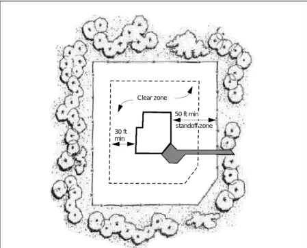
as far from the target facility as practical. Figure 3-1 shows the distances required to limit building damage to particular levels (including the levels of protection described above) for a range of bomb weights. All bomb weights are given in terms of equivalent pounds of trinitrotoluene (TNT), which is a standard way of identifying all explosives regardless of their composition. The example in Figure 3-1 is a building of conventional construction (common, unhardened construction). Buildings built without any special construction at these standoff distances will probably withstand the explosive effects. Conventionally constructed buildings at standoff distances of less than those shown in Figure 3-1 will not adequately withstand blast effects. (Refer to TM 5-853-1 for information on hardening buildings to resist a blast.) Do not allow vehicles to park within the established standoff distances. Recognize that this restriction can result in significant operational and land-use problems.
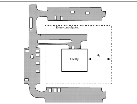
3-8. Exclusive Standoff Zone. When an exclusive standoff zone is established, do not allow vehicles within the perimeter unless they have been searched or cleared for access. The zone ’s perimeter is established at the distance necessary to protect the facility against the highest threat explosive. All vehicles should be parked outside the exclusive standoff zone; only
Clear zone
standoff zone 50 ft min 30 ft
[image:24.612.91.540.342.705.2]min
maintenance, emergency, and delivery vehicles should be allowed within the zone after being searched. Figure 3-2 shows an exclusive standoff zone.
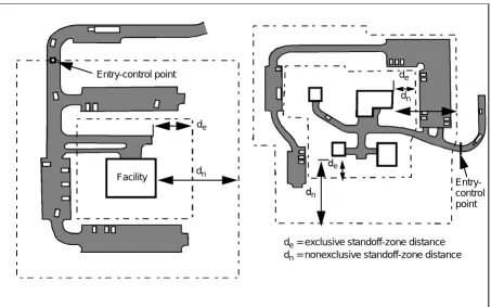
3-9. Nonexclusive Standoff Zone. A nonexclusive standoff zone is established in a location having a mixture of cars and trucks (with relatively few trucks). A nonexclusive standoff zone takes advantage of aggressors being able to conceal a smaller quantity of explosives in a car than they can in a truck. Therefore, a nonexclusive standoff zone includes inner and outer perimeters. The inner perimeter is set at a distance corresponding to the weight of explosives that can be concealed in cars. The outer perimeter is set at a distance associated with the weight that can be placed in trucks (refer to TM 5-853-1). With these two perimeters, cars can enter the outer perimeter without being searched but they cannot enter the inner perimeter. Trucks cannot enter the outer perimeter, since it is established based on what they can carry. Figure 3-3 shows a nonexclusive standoff zone. The nonexclusive standoff zone provides the advantages of allowing better use of the parking areas and limiting the number of vehicles that need to be searched at the outer perimeter. .
Entry-control point
de Facility
[image:25.612.74.524.326.667.2]de= exclusive standoff-zone distance
Vehicle Barriers
3-10. Two types of vehicle barriers are used for vehicle bombs—perimeter and active barriers. The type of barrier used for a moving vehicle bomb differs from the barrier used for a stationary vehicle bomb. The barrier used for a stationary vehicle bomb does not have to stop a vehicle ’s motion. The goal for that barrier is to make anybody driving through the barrier noticeable. The assumption is that the aggressor’s goal in the stationary vehicle bomb is to park the vehicle and sneak away without being noticed. Crashing through a barrier would be noticeable. Barriers for the moving vehicle bomb need to stop the vehicle ’s motion; they must be much more substantial.
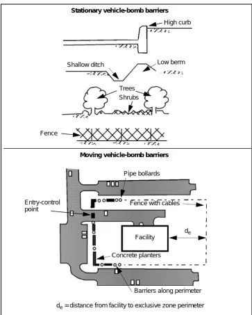
3-11. Perimeter Barriers. Perimeter barriers are fixed barriers placed around the entire perimeter of a standoff zone. Anything that presents a fixed obstacle will work for the stationary vehicle bomb. Common applications include chain-link fences, hedges made of low bushes, and high (over 8 inches) curbs. Aggressors driving through such barriers are likely to be noticed. Barriers capable of stopping moving vehicles include chain-link fences reinforced with cable, reinforced concrete “Jersey barriers”, pipe bollards, planters, ditches, and berms. When barriers such as the Jersey barriers and planters are used to stop moving vehicles, they must be anchored into the ground to be effective. The cables in the reinforced fence also have to be anchored into the ground or partially buried. Spaces between barriers should
Entry-control point
de
dn Facility
de dn
de dn
Entry-control point
[image:26.612.93.546.105.388.2]de= exclusive standoff-zone distance dn= nonexclusive standoff-zone distance
be no greater than 4 feet. Figure 3-4 shows common perimeter barriers for stationary or moving vehicle bombs. Refer also to TM 5-853-1.
3-12. Active Barriers. Active barriers are placed at openings in perimeters where vehicles need to enter or exit. These barriers must be able to be raised and lowered or moved aside. For the stationary vehicle bomb, barriers can be as simple as chain-link, pipe, or wooden gates that can be raised and lowered. Aggressors crashing through any of these or similar obstructions will likely draw attention. For the moving vehicle bomb, the barriers are heavy structures and have many construction and operations considerations
Shallow ditch Low berm
Trees
Fence
Fence with cables Pipe bollards
Concrete planters
Barriers along perimeter Facility
de= distance from facility to exclusive zone perimeter de Shrubs
Moving vehicle-bomb barriers High curb Stationary vehicle-bomb barriers
[image:27.612.161.524.225.678.2]Entry-control point
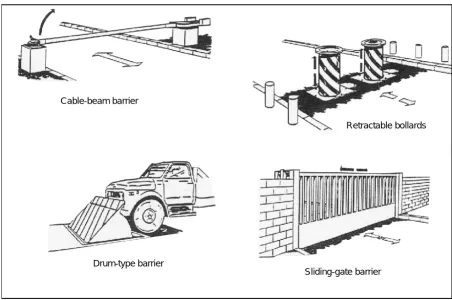
associated with them. These barriers may stop vehicles weighing up to 15,000 pounds and travelling 50 miles per hour. They commonly cost tens of thousands of dollars (refer to TM 5-853-1). Some common active vehicle barriers are shown in Figure 3-5. For temporary or deployed conditions, park a vehicle across an opening and move it aside to grant access.
Speed Control
3-13. It is important to control the speed of a vehicle approaching a barrier used for a moving vehicle bomb. The energy from a vehicle that a barrier must stop increases as its speed increases. The energy also increases with more weight, but the effect of speed is much greater. Therefore, decreasing the vehicle ’s speed results in smaller and less costly barriers. The best way to limit a vehicle ’s approach speed to perimeter barriers is to place or retain obstacles in potential approach paths. The vehicles are forced to reduce speed when going around these obstacles. The same principle applies for road approaches. Placing obstacles in a serpentine pattern on the road forces a vehicle to reduce its speed (see Figure 3-6, page 3-8). If the vehicle hits the obstacles instead of going around them, they are still slowed down. Other means to slow vehicles include forcing them to make sharp turns and installing traffic circles.
Cable-beam barrier
Retractable bollards
Drum-type barrier
[image:28.612.89.541.359.659.2]Sliding-gate barrier
BUILDING ELEMENTS
3-14. Once the standoff distance is established and the site has been laid out, the designers can select the building components necessary to protect the assets against the threat explosives at the standoff distance. The building components include the walls, roofs, doors, and windows. Detailed design issues related to these building elements are covered in TM 5-853-1.
Walls and Roofs
3-15. If the distances shown for the desired damage levels in Figure 3-1, page 3-3, cannot be enforced, the building’s walls and roofs will need to be strengthened. This can be achieved in new construction by using reinforced masonry or reinforced concrete in the walls and reinforced concrete in the roof. When the standoff distance is not available for existing construction, a more detailed analysis may be required to determine what the explosion’s impact will be on the structure. When the construction is inadequate, more standoff distance should be investigated or the engineers should apply specialized techniques for retrofitting the construction to increase its strength.
Windows
3-16. Historically, glass fragments have caused about 85 percent of injuries and deaths in bomb blasts. There are two basic approaches to mitigating the effects of bomb blasts on glass—retrofitting the windows with film or curtains and using blast-resistant glazing.
3-17. Retrofitting Windows. One of the most common means of decreasing the hazards from broken glass is to install fragment-retention film on the glass. The film is a plastic (polyester) sheet that adheres to the window glass with a special adhesive. The film does not strengthen the glass; but when the
d
2
4ft
1
0ft
Perimeter barrier Obstacles
d = distance to barrier
glass fragments stick to the film, and the film either stays in the window frame or falls into the room in one or more large, relatively nonhazardous pieces instead of many small, lethal pieces. Another retrofit approach is to install a blast curtain or a heavy drape behind the window. The curtain or drape catches the glass fragments. The curtains are generally used with retention film. Another retrofit technique is to use fragment-retention film with a metal bar placed across the window. This “catcher bar” catches the window. The designs for this and other types of retrofit devices are complicated and require specialized engineering-analysis tools. The retrofit techniques are generally thought of as providing a lower level of protection than the glazing replacement techniques. For deployed locations, removing the windows and covering them with plywood minimizes the danger.
3-18. Blast-Resistant Glazing. To achieve higher levels of protection, the window glass must be replaced and the window frame should be reinforced. Because of its expense, this procedure is generally limited to new construction and major renovations. Special blast-resistant glazing and frames are available that use either tempered glass or a plastic glazing (such as polycarbonate). Another promising type of blast-resistant glazing is laminated glass, in which several layers of common glass are adhered together with a special interlayer. The resulting laminated construction is usually stronger than common glass while retaining the same thickness. The interlayer acts similarly to fragment-retention film. For deployed locations, a means of minimizing the danger of windows is to remove them and replace them with plywood.
Doors
3-19. Doors are another building component particularly vulnerable to an explosive blast. Common metal and wood doors provide little resistance to a blast. The two ways to address the problem of doors is to install them in foyers or to replace them. Glass doors or doors containing windows should be avoided.
Foyers
3-20. Door hazards can be reduced by installing doors in foyers during construction or by adding foyers to existing buildings. When a door is located in a foyer and the outer door fails, the outer door flies into a wall instead of the building’s interior (see Figure 3-7, page 3-10). The inner door then has a greater chance of remaining intact. This option generally provides a low level of protection.
3-21. Another option is to replace the doors with specially constructed blast-resistant doors and frames. These doors are commercially available and can provide a high level of protection, but they are very expensive and heavy. The doorframe must be made of the same type of material and provide the same level of protection as the door.
DETECTION ELEMENTS
into the perimeter through an entry-control point. The recommended levels of searches depend on the required level of protection (see TM 5-853-1). Guards can be stationed at entry-control points continuously, or they can be summoned to an entry-control point when access is needed. The latter is commonly the case for the inner perimeter of exclusive standoff zones where only delivery and maintenance vehicles need access.
EXTERIOR ATTACK
3-23. An exterior attack is a physical attack using weapons such as rocks, clubs, improvised incendiary devices (IIDs) such as Molotov cocktails, explosives such as improvised explosive devices (IEDs), and hand grenades. The explosives can be thrown at or placed near a facility’s exterior. Examples of IEDs for this tactic range from pipe bombs and hand grenades to briefcase-sized explosives.
GENERAL-DESIGN STRATEGY
3-24. Because the exterior attack is directed at a facility's exterior surfaces, the general-design strategy is to keep aggressors away from the facility (at a standoff distance) and, if necessary, to harden the facility's exterior components to resist the effects of weapons and explosives. A standoff distance from the facility reduces the degree of hardening required to resist weapons effects. When briefcase-sized bombs are a threat, an obstacle-free zone should be established around the facility and the explosives placed within should be detected and disarmed.
LEVELS OF PROTECTION
3-25. The levels of protection for exterior attacks are similar to those for vehicle bombs. Levels of protection vary based on the level of building damage and asset injury or damage allowed. However, due to the limited sizes of explosives involved in this tactic, the damage to the building will be much
Building exterior
Alternate offset opening Offset
opening
Foyer
SITE-WORK ELEMENTS
3-26. Site-work elements for exterior attacks are relatively limited because the explosive weights are more limited. Large standoff distances are not a consideration. The common approach to site-work elements is to lay out a standoff zone of about 50 feet and to provide a fence or perimeter barrier about 7 feet high. The purpose of the standoff is to make it harder for aggressors to throw pipe bombs and hand grenades at targets inside the perimeter. Trees can be left around the perimeter to make it harder for aggressors to throw explosives over the fence. The remaining component of site-work elements is a clear zone around the facility. A clear zone is applied so that anything placed in that area can be detected visually. This limits the aggressor’s ability to place explosives near the target facility.
BUILDING ELEMENTS
3-27. Building elements for exterior attacks are similar to those for vehicle bombs. For small IEDs and IIDs, the building-element requirements do not increase the cost of the building significantly. For larger, briefcase-sized bombs, the measures are more significant than for incendiary devices but less than for vehicle bombs.
Walls and Roofs
3-28. Walls and roofs are not a problem with small explosives. Conventional construction normally provides adequate protection. Walls with 6-inch reinforced concrete or 8-inch, grout-filled, reinforced masonry will withstand the effects of typical pipe bombs or hand grenades. The corresponding roof construction is 6-inch reinforced concrete. In the case of briefcase-sized bombs, considerations similar to those discussed for vehicle bombs need to be employed.
Windows
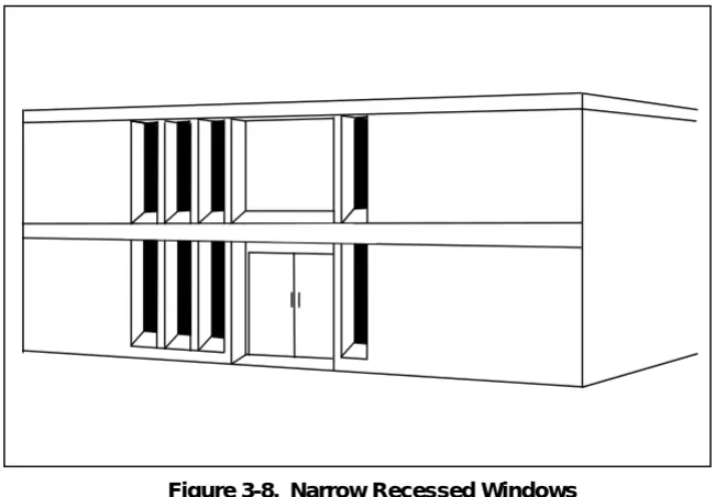
3-29. A significant goal when constructing windows is to make them difficult to throw an explosive or incendiary device through, especially when considering smaller explosives. This is accomplished by constructing smaller windows or making narrow windows (see Figure 3-8, page 3-12). For existing windows, parts of the windows can be covered to achieve a narrow effect. These windows still may be susceptible to breakage due to explosive effects, even from the smaller explosives. This problem is solved by installing 3/4-inch-thick plastic (polycarbonate) glazing or by raising the windows over 6 feet high to develop a small standoff distance (as shown in Figure 3-9, page 3-12). A 3/4-inch glazing will also stop grenade fragments. Fragment-retention film, a blast curtain, or a heavy drape as described in vehicle-bomb tactics are also good applications for small bombs.
Conventionally Constructed Doors
only a low level of protection. To achieve higher levels of protection for briefcase-sized bombs, blast-resistant doors must be installed.
[image:33.612.166.491.124.350.2]3-31. The requirements to meet the levels of protection for larger explosives are similar to those described for vehicle bombs, but they will not stop grenade
Figure 3-8. Narrow Recessed Windows
level of protection, but blast-resistant glazing is required to achieve a higher level of protection.
DETECTION ELEMENTS
3-32. Other than awareness of aggressor activity on or outside the site, detection is only a specific design goal where briefcase-sized bombs are anticipated. When that is the case, the clear zone around the building must be visually monitored so that any objects placed in it are detected. At higher levels of protection, visual surveillance is augmented by IDSs.
STANDOFF WEAPONS
3-33. The standoff-weapons tactic includes the use of AT weapons and mortars. In both of these tactics, the aggressor fires weapons at assets located in the protected facility from a distance. An AT-weapon attack requires a clear LOS to the target, while mortars can fire over obstacles and only need a clear line of flight.
GENERAL-DESIGN STRATEGY
3-34. Standoff-weapons attacks cannot be detected reliably before they occur. Protective design to resist these tactics relies on blocking LOSs to protected areas of a facility or hardening the facility to resist the particular weapon’s effects. The approaches to protection against mortars and AT weapons differ from each other and will be discussed separately. Detection measures are not applicable for these tactics.
LEVELS OF PROTECTION
3-35. There are two levels of protection against both mortars and AT weapons. For AT weapons, the low level of protection depends on detonating the AT round before it hits the target facility. The high level of protection avoids the risk associated with that and hardens the building to resist the direct impact of the AT round.
3-36. For mortars, the low level of protection involves allowing some areas of the facility to be sacrificed. Those spaces provide a buffer to the assets to be protected. The assets within the sacrificial areas and the areas themselves may be destroyed. At the high level of protection, the building’s exterior fully resists the mortar rounds and there are no sacrificial areas.
SITE-WORK ELEMENTS
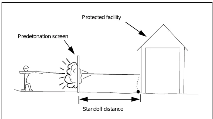
wooden fence) will detonate the round unless it has spaces in it. The screen distances vary from less than 10 feet to almost 40 feet, depending on the building construction (see TM 5-853-1). This measure only applies to the low level of protection.
BUILDING ELEMENTS
3-38. Building elements for AT weapons and mortars involve the building’s layout. This includes the materials used in the construction.
Layout
3-39. A building’s interior layout is only an issue for the low level of protection against a mortar round. The layout issue involves designating sacrificial areas in which unimportant assets are located. The assets to be protected are located in a hardened interior layer. Figure 3-11 includes a plan view (from above). The sacrificial area has to be both around and above the protected area in case a mortar round comes from above. If such a layout is not feasible, other options include going to a higher level of protection and either hardening the entire building or building the facility underground (which are both very expensive).
Walls and Roofs
3-40. Walls and roofs must offer protection against both AT weapons and mortar rounds. The design of walls that protect against AT weapons varies with the level of protection. For the low level of protection where the round is predetonated, the walls can be of conventional construction, varying with the standoff distance from the predetonation screen to the wall. For higher levels of protection, the walls must resist the full effect of the round, requiring the
Protected facility
Predetonation screen
[image:35.612.161.523.121.324.2]Standoff distance
protecting against AT weapons because it is difficult to get direct LOSs to roofs. If such LOSs are possible, the roof should be designed like the walls.
3-41. To provide protection against mortar rounds, walls and roofs should be designed to resist the explosive effects in the rounds at the standoff distance that the sacrificial space provides. In the case of sacrificial areas, the walls can be of common construction. The interior protected-area walls are then designed of reinforced concrete or reinforced masonry for the standoff distance those sacrificial walls provide. When the walls must resist the full effect of the rounds (as in the higher level of protection), they are likely to be very thick (up
3 1
Asset
Asset
Asset
Multiple assets with shared 1st, 2nd, and 3rd layers
A A
1
Multiple assets
shared 2nd and 3rd layers
C A A
Multiple assets with shared 2nd and 3rd layers
C 1
1
2
2 3 2 3
1
2
Asset A
Asset B 2
1
1
Asset with 3 layers
Asset with shared outer layer Multiple assets with 3
shared layers
4 1
3
4
to 30 inches of reinforced concrete for some improvised mortars). Similar considerations should be made for roofs. Roofs are designed to take the direct effects of the round or to take the round at the standoff distance provided by the sacrificial area.
Doors and Windows
3-42. It is impractical to provide doors and windows that are resistant to mortar rounds and AT weapons. Windows should only be used in sacrificial areas where there is a mortar threat. When there is an AT weapon threat, windows can only be used where the round is predetonated. The windows should be narrowed or raised to present a smaller target (see Figures 3-8 and 3-9, page 3-12). Doors should be placed in foyers (see Figure 3-7, page 3-10) for protection against AT rounds and to achieve a low level of protection against mortars. Blast-resistant doors are necessary to achieve a high level of protection against mortar rounds.
BALLISTICS
3-43. In a ballistics tactic, aggressors fire small arms at assets from vantage points outside of the target facility’s control. Ballistic attacks cannot be detected reliably before they occur.
GENERAL-DESIGN STRATEGY
3-44. Protective measures to resist these tactics rely on blocking LOSs to protected areas of a facility or by hardening the facility to resist the ballistic effects. This strategy focuses on assets within buildings. Protecting people or property in the open is difficult and can only be addressed through operational measures. Detection measures are not applicable for this tactic.
LEVELS OF PROTECTION
3-45. There are only two levels of protection for this tactic. The low level of protection depends on blocking LOSs to assets. This strategy assumes that the aggressor cannot hit what he cannot see. The risk of an aggressor firing into a building randomly and hitting something is what makes this the low level of protection. The high level of protection involves hardening building components to resist the ballistic effects. These strategies can be thought of as either hardening or hiding.
SITE-WORK ELEMENTS
3-46. Site-work elements are of limited use for the ballistics tactic. When they are applied, they are used to obstruct LOSs from vantage points outside of the site, which is consistent with the low level of protection. The LOSs can be blocked using trees, other buildings, motor pools, or fences.
BUILDING ELEMENTS
Walls and Roofs
3-48. Walls and roofs are inherently opaque, so it is easy to achieve the low level of protection (hiding) with them. Achieving the high level of protection (hardening) for walls and roofs can be done within conventional construction using reinforced concrete, concrete-masonry units (CMUs), or clay brick. The material’s required thickness is shown in Table 3-1. The thicknesses of CMUs and clay brick are nominal, meaning they do not represent the actual thickness of the material; they represent the thicknesses at which those materials are commercially available. Steel plates (mild steel and armor steel) and bullet-resistant fiberglass can be used to retrofit existing building components that would not provide the needed bullet resistance.
Windows
3-49. Windows can include openings in walls and skylights, although skylights are only an issue where there are LOSs to them. When skylights require protection, treat them like windows. Achieving the low level of protection (hiding) for windows requires making it difficult to see through them, such as installing reflective film on the glass. An aggressor cannot see through the windows during daylight while it is lighter outside than inside, but he may see through them at night when the opposite might be true. Drapes or blinds that can be closed at night address that vulnerability. To achieve the high level of protection requires bullet-resistant window assemblies. These are commercially available for a wide range of ballistics types. They are purchased as manufactured-and-tested assemblies (including glazing and frames, both of which are equally bullet-resistant). The glazing materials and thicknesses and the framing details are proprietary to their manufacturers. The manufacturers make them according to industry test standards to ensure an effective product.
Doors
3-50. Doors without glass easily meet the requirements for the low level of protection. Meeting the high level of protection requires the installation of bullet-resistant door assemblies. Doors can be installed in foyers so that there is no direct LOS into assets within the building (see Figure 3-7, page 3-10).
FORCED ENTRY
3-51. In the forced-entry tactic, an aggressor tries to forcibly gain access to assets. He may use tools or explosives to breach building components or other
Table 3-1. Required Thicknesses, in Inches
Ballistics Type Reinforced Concrete
Grouted CMU*
Clay Brick*
Steel Plate Bullet-Resistant Fiberglass
Mild Armor
.38 special 2 4 4 1/4 3/16 5/16
9 mm 2 1/2 4 4 5/16 1/4 7/16
7.62 and 5.56 mm 4 6 6 9/16 7/16 1 1/8
7.62-mm AP 6 1/2 8 8 13/16 11/16 N/A
GENERAL-DESIGN STRATEGY
3-52. The general-design strategy for forced entry i