Dynamic Block-Edge Masks (BEMs) for
Dynamic Spectrum Emission Masks (SEMs)
Timothy K. Forde, Linda E. Doyle and Barıs¸ ¨
Ozg¨ul
CTVR, The Telecommunications Research Centre,
Department of Electronic and Electrical Engineering,
University of Dublin, Trinity College, Dublin, Ireland.
{
fordeti, ledoyle, ozgulb
}
@tcd.ie
Abstract—This paper explores the evolving role of transmitter spectrum masks in the emerging paradigm of service and technology neutral spectrum planning. We advocate the use of more dynamic approaches to spectrum mask generation and design. Furthermore, we advocate a role for such masks in the implementation of dynamic spectrum access networks. In this paper we distinguish between the block-edge mask (BEM) and the spectrum emission mask (SEM). A block-edge mask specifies permitted power levels over the block of spectrum of interest and its neighbouring blocks. The spectrum emission mask on the other hand describes the actual emission profile of a device. We show how advancements in technologies, especially in the area of cognitive radio and reconfigurable networks, make the notion of dynamic SEMs a reality and we argue that a more dynamic approach to BEMs opens the way for enabling technology and service neutrality in spectrum management. We present five different possible interpretations for the dynamic BEM. While recognising that the dynamic BEM will prove challenging on
both a technological and regulatory front we turn to theWireless
Access Policy for Electronic Communications Services(WAPECS) framework as a solid starting point.
I. INTRODUCTION
This paper focuses on spectrum masks. Spectrum masks are employed by the majority of wireless transmitters in use today and are a proven technique for limiting the creation of harmful interference. These masks are defined by a set of breakpoints which specify the maximum permitted transmitted power lev-els within a defined bandwidth at a particular frequency offset from the carrier frequency of the signal. Masks are typically designed to accommodate the requirements of the system waveform while keeping out-of-band (OOB) emissions below an acceptable power level for systems in adjacent channels. Hence spectrum masks are a regulatory tool for managing
adjacent channel interference. Masks can be applied to devices that may vary from a high-power TV transmitter, to a macro-cellular base-station, to a cell-phone or a nomadic broadband transceiver.
Contemporary spectrum masks are made for a highly static world and are more suited to regimes in which specific This material is based upon work supported by Science Foundation Ireland under Grant No. 03/CE3/I405 as part of CTVR, The Telecommunications Research Centre, at Trinity College Dublin, Ireland.
technologies are used in specific spectrum bands to deliver
specific services. We are however interested in a much more flexible world that is based on the premise oftechnology and service neutrality. In a technology and service neutral world any service can be offered in almost any band, subject to it being economically efficient to do so. Any two networks can be (spectral/spatial/temporal) neighbours. Spectrum bands can change ownership and new technologies can be introduced as and when needed in a fluid and dynamic manner heralding the way for effective spectrum trading. Furthermore, we see dynamic spectrum access (DSA) as a subset of the full tech-nology and service neutral world. DSA networks will operate in a technology and service neutral manner (using whatever technologies they like, delivering whatever services they wish) around legacy users. Service and technology neutrality calls for more dynamic ways of managing spectrum. In this paper we make the argument that while spectrum masks are a useful concept, as spectrum management becomes more dynamic, we need dynamic masks.
Rather than use the generic term spectrum mask we think it is more useful to distinguish between block-edge masks (BEMs) and spectrum emission masks (SEMs). In the opening paragraph of the paper we have more or less defined the block-edge mask. A block-edge mask specifies permitted power levels over the block of spectrum of interest and its neighbouring blocks. The spectrum emission mask on the other hand describes the actual emission profile of a device. The SEM must comply with the BEM in order to keep within the terms of the license. Hence BEMs relate more correctly to the licence conditions for a block of spectrum, whereas the SEMs relate to the actual emissions of the radio equipment. If we use the BEMs and SEMs terminology in the context of current regimes we would say that regulators (and standards bodies) define BEMs and manufacturers ensure that the SEMs of different communication devices conform to the BEMs associated with the spectrum in which they operate.
In recent years, however, we have seen that radios are now capable of manipulating and shaping the waveforms they transmit in an increasingly dynamic fashion. Put another way, we can argue that it is possible now to generate SEMsin situ
the manufacturer’s design. In other words there is such a thing as a dynamic SEM. The natural question to follow is whether there can be such a thing as a dynamic BEM and, if so, what form would such an entity take. Hence, the purpose of this paper is twofold. First, we want to show how the notion of the SEM is being redefined through advances in technology. Secondly, we want to explore the idea of dynamic BEMs and motivate their use in a service and technology neutral world. Whilst we acknowledge that there are a number of different approaches to transmitter masking [2], the BEM approach is one that lends itself to an incremental move towards a more dynamic environment. The title of the paper attempts to capture this idea in suggesting that BEMs should follow in the footsteps of the SEMs.
Central to this paper is an understanding of adjacent channel interference. Hence, section II gives a brief tutorial on the topic and highlights some of the key concepts that are built upon in this paper. Section III then discusses how adjacent channel interference is currently controlled and in doing so more fully fleshes out the the BEM and SEM concept. The key point to take away from this section is that spectrum masks as we know them are designed for highly static scenarios that are well-known in advance; deployment scenarios that can be problematic are avoided. Section III concludes by focusing on the world of the future, a world of technology and service neutrality and a world in which the spectrum mask will need to play a greater role. Section IV draws attention to the dynamic SEMs and shows how developments in technology have made this idea a reality. This section essentially lays the ground for the natural follow-on to dynamic BEMs. Section V makes one of the major contributions of the paper and speculates on the different ways BEMs can be made more dynamic and the potential roles for these kinds of masks. The difficulties and challenges of creating these BEMs is acknowledged. Section VI posits that the WAPECS framework, a framework for technology and service neutrality, can provide a basis for designing dynamic BEMs while acknowledging much more work is needed. Finally, Section VII concludes the paper. The work in this paper draws heavily on three key reports of the Electronic Communications Committee (ECC) within the European Conference of Postal and Telecommunications Administrations (CEPT), namely [1], [2], [3].
II. ADJACENTCHANNELINTERFERENCE
Adjacent channel interference ‘starts off’ as a simple enough concept. The RF spectrum is generally broken up into con-tiguous blocks of frequencies which are allocated to different uses. The systems using these blocks in a given geographical region then transmit according to the technical and service needs of their particular system. However, transmissions are not perfect and hence are not confined to the allocated blocks and leakage into adjacent bands occurs causing interference to systems working in the adjacent bands.
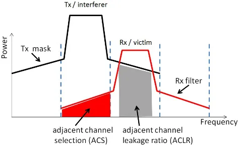
[image:2.595.310.549.98.244.2]Firstly, it is important to stress that both the transmitter and the receiver have a role to play, Figure 1 captures this. In Figure
Fig. 1. The basic causes of adjacent channel interference. The transmitter and the receiver play a role.
1 we see that the transmitter is ‘sloppy’ in its transmission and there is power in adjacent bands that is received by the receiver. We also see that the receiver is ‘imperfect’ and hence picks up signals that are outside its own band of interest. The adjacent channel selectivity of the receiver determines exactly how much interference is picked up. Hence, the detrimental effect of out-of-band (OOB) emissions is a combination of sloppy transmission, or transmissions that lie outside the wanted/legal pass-band of the wanted/legal signal, and unfocussed filtering at the receiver. This is the first key point to be made about adjacent channel interference. Secondly, there is a spatial element to adjacent channel inter-ference. We are of course dealing with communication systems that cover the same geographical area but within that area transmitters and receivers from different systems on adjacent channels can find themselves in a variety of positions in relation to each other. If transmitters are co-located then they will experience each other’s peak power. As power dissipates with distance from the transmitter, the interference experienced by one device from another also decreases. In other words the distance between the transmitter and receiver will impact on theadjacent channel leakage ratioexperienced by the receiver in Figure 1. Consequently the nature of the distances between what we call interferers and victim receivers is an important consideration in the calculation of the impact on adjacent channel interference.
the various different kinds of interferences that can result can be found in [4].
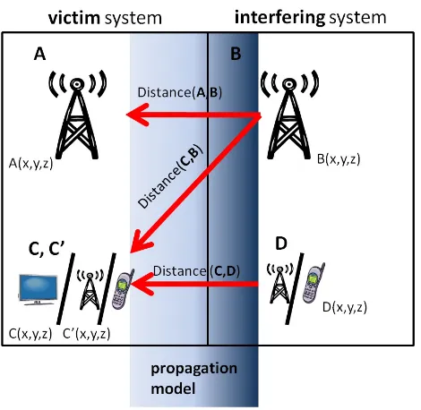
Figure 2 illustrates two systems occupying adjacent frequency blocks operating over the same geographical area and attempts to capture the concepts mentioned in the last two paragraphs. Consider for the moment how the system on the right affects the system on the left; in this analysis we treat the system on the left as the victim system and the system on the right as the interfering system. Of course, any complete analysis must also look at the opposite scenario. In Figure 2, the system on the right is an FDD downlink system and the one on the left is a TDD system. This allows us to establish that interference can occur along three paths marked in the diagram; from transceiver B to transceiver A, from transceiver B to transceiver C and from transceiver D to transceiver C′. For the last interference path, from D to C′, the victim terminal stations in this case will not be those at C. As the interfering system is using FDD technology, transceivers B and D will be operating on their own frequencies which are separated by a significant duplex spacing, e.g. typically 100MHz separation for 5MHz FDD channels [4]. As such, the interfering FDD system’s basestation and terminal stations have different adjacent channel neighbours and must consider two sets of terminal station devices, i.e. victim system C on the interfering basestation A’s frequency and victim system C′ on interfering terminal station D’s frequency.
Fig. 2. This figure depicts two system operating on adjacent frequencies; one system interferes with the other system along the paths indicated. The two systems operate over the same geographical area.
If the systems in Figure 2 consist of static devices, then the distances between the interferers and victims can be readily calculated, and using propagation models appropriate to the frequency and terrain, the adjacent channel interference can be calculated. If some elements of the systems are mobile, such as elements C, C′and D, then it is harder to make assumptions about how these devices will be separated and consequently
determine the adjacent channel interference that will occur.1
Finally, it is not just whether neighbouring systems are TDD and FDD that matters. The power levels and density of the networks also can have a significant impact. An example can be used to illustrate this and is shown in Figure 3. TV transmission systems, whether analogue or digital, are generally characterised by high-power transmitters that cover a large area. For DVB-H coverage, a more dense network may be required, but in the main DVB-T follows a pattern similar to the analogue transmission systems. In Figure 3 both systems are operating in the same geographical area but on adjacent frequencies.
Fig. 3. Unlike Adjacent Systems: A high-power TV transmitter is adjacent to lower-density DVB-H transmitters. The DVB-H transmitterspunch holes
at the edge of the DVB-T transmitters service area. (Derived from an image that appears in [3])
While an individual DVB-H transmitter is designed such that it will not cause interference to the edge coverage of the DVB-T, scenarios can arise in which the aggregate co-channel interference actually does cause a problem. In essence, the transmissions from the dense network of DVB-H transmitters can constructively combine in such a manner so as to cause interference. The overall increase in power does not just mean an increase in power in the frequency band devoted to the DVB-H transmissions but an associated increase in power in the adjacent channels, i.e. the channels in which the DVB-T system is operating. What this looks like in reality is a set of holes in the coverage of the DVB-T system as shown in Figure 3 [3].
So while adjacent channel interference does indeed start as a simple concept there are many complexities to be taken into account. In summary, the adjacent channel interference expe-rienced is heavily dependent on the technical characteristics of
1Typically, the regulatory literature considers separation distances of the
[image:3.595.51.286.385.614.2]the adjacent systems, the geographical spread of the system in the given geographical area and the types of services the systems are delivering.
III. CONTROLLINGADJACENTCHANNEL
Adjacent channel interference is managed in a number of different ways by regulators. Taking a simplified overview, regulators do the following:
1) Firstly, regulators still stipulate which communication systems can be neighbours in order to minimise the occurrence of adjacent channel interference in the first place. So for example the situation described in Figure 3 would normally be completely avoided.
2) Secondly, guard bands are inserted between adjacent systems. A guard band allows some leakage from the operating communication system into the adjacent band to take place but as there are no systems operating in guard band, the leakage does not cause a problem. 3) Thirdly, regulators make use of spectrum masks to
control the amount of adjacent channel interference that leaks into neighbouring systems.
[image:4.595.321.527.64.230.2]The primary goal of the spectrum mask is to contain the power of the signal within certain bounds such that the power that leaks into adjacent channels causes a tolerable level of interference to the victim receivers. As mentioned in the outset of this paper we use the term block-edge mask (BEM) as a more precise use of terminology. The BEM is defined as a function of frequency and power. The BEM generally has three components, namely the in-block limit, relative to the edge of the block of spectrum. The transition level (which may be a series of steps), and a baseline level for emissions beyond the edge of the mask. These are shown in Figure 4.
Fig. 4. A Block Edge Mask (Derived from an image that appears in [1])
The role for the regulator is in stipulating what the levels will be. In order to determine the baseline emissions for beyond the edge of the block, many of the issues discussed in section II must taken into account. Figure 5 shows five BEMs that are currently in use for different standards ranging from low-power ISM band devices, e.g. IEEE 802.11, to high-low-power TV transmitters.
−1.5 −1 −0.5 0 0.5 1 1.5
−120 −100 −80 −60 −40 −20 0
Normalized Frequency
Magnitude (dBr)
[image:4.595.307.550.285.479.2]IEEE 802.16 "Unlicensed" IEEE 802.11 a/g ETSI DVB−T "critical" IEEE 802.22 proposed FCC DTV
Fig. 5. Examples of different BEMs which have been defined for use in different communication systems. WiMAX, WiFi and Digital TV examples are included.
Fig. 6. The real SEM can be seen under the BEM on the above measurement system. The device in question is an IEEE 802.11g device.
The SEM, on the other hand, describes the actual emission profile of a device. Figure 6 depicts a SEM of an IEEE 802.11g device. The device has been designed to conform with a BEM that has been specified by the regulators and standards bodies. Given that the BEM is static, equipment manufacturers can custom design the transmitter hardware such that a spectrally efficient SEM is achieved. An efficient SEM is one which most closely approximates the profile of the BEM.
[image:4.595.49.284.496.632.2]men-tioned previously some complex scenarios which adversely affect adjacent channel interference are simply not allowed. All of this means that baseline transmission levels beyond the edge of the mask can be calculated.
This relative ease of control of adjacent channel interference disappears when you move towards technology and service neutrality. In such a world any service can be offered in any band. Any two networks can be (spectral) neighbours and scenarios such as those depicted in Figure 3 can arise. Dy-namic spectrum access regimes or spectrum trading scenarios mean neighbours can change over time (albeit at different time scales). In such a world it will not be possible to decide which systems are permitted to be neighbours. At the least, there will be less constraints and in the most ideal of technology and service neutrality worlds there will be none. In such a world there may be no room for the pre-assigned guard band. Hence, one of the only feasible tools remaining is the mask. But even given the current approaches to mask design [2], the bottom line is that static masks themselves are not up to the task. And that is where the need for dynamic masks comes in.
IV. ALREADY A DYNAMICSEM
[image:5.595.313.548.154.319.2]We can look to the advances in the SEM situation to start the discussion of dynamic masks. Rather than thinking about the SEM as something that is purpose-designed by the manufactur-ers as per Figure 6, the advent of technologies such as software radio, cognitive radio and reconfigurable networks means that a SEM is something that can be generated in situ. Focusing on cognitive radio for the purposes of the discussion we see that these radios can sense their environment, decide on how to best configure themselves and subsequently transmit. Different waveforms, modulation techniques, power levels and antenna combinations can be selected to sculpt the transmitted signal. Figure 7 captures this idea in a simplistic way and shows how a cognitive radio lowers its power levels automatically to create a BEM-compliant output.
Fig. 7. A Block Edge Mask with two Spectrum Emission Masks: The high-power SEM violates the BEM, the low-high-power SEM conforms to the BEM. (Derived from an image that appears in [1])
In Figure 7 the situation is simple. However the SEM is not spectrally efficient. There are now numerous techniques which exist which allow highly adaptive (cognitive) radios to sculpt
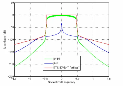
the emission profile of the device in a more effective manner. Figure 8 shows some advanced techniques at play. Here an orthogonal frequency division multiplexing (OFDM) wave-form has been shaped using some digital signal processing techniques to fit within a BEM. The BEM in this case is the critical 802.16 Mask taken from Figure 5 and is marked in red. The blue trace shows the signal that arises when no
Fig. 8. Shaping of an OFDM waveform to fit within a BEM
advanced signal processing is applied. In this case the OFDM signal is reduced to a small few subcarriers, to ensure that the OOB emissions are below the mask. But the green trace shows how the signal can be shaped, using advanced techniques, to take most advantage of the available spectrum and power. The shaping used involves some kind of windowing of the original OFDM signal and the parameterβ2in the figure is a parameter
of that process. The main message is that the radio does not need to be hard-coded to use a particular waveform by the manufacturer but instead is capable of creating a suitable BEM compliant waveform in situ.
Figure 8 shows the results of just one approach. There is an enormous amount of research in the field today with a large emphasis on the shaping of OFDM waveforms, though of course the literature does not speak about the process as being a dynamic SEM [5], [6], [7]. The reality is that there are a range of actions relating to the emission profile of the device that can be taken by a highly flexible radio that is aware of its surroundings; all of these actions ultimately concern the creation and control of dynamic SEMs.
V. ONTO ADYNAMICBEM
We now turn to the idea of a dynamic BEM. There are many potential interpretations of the meaning of ‘dynamic’ when it comes to the BEM. The purpose of this section is to work through those interpretations. The interpretations listed here do not necessarily apply to all application areas.
2β corresponds to the symbol duration extension factor used for
[image:5.595.47.282.530.663.2]A. Dynamic Access to a Collection of Static BEMs
The first way in which BEMs may be more dynamic is for a communication system to choose the BEM based on the circumstances in which it finds itself rather than be given a BEM, with which it must comply, in advance. In this case we can imagine a collection of different BEMs from which the communication system must select the appropriate BEM. This notion is not beyond current regulatory thinking. In November 2008, the FCC released rules and guidelines for use of TV whitespace [8]. The FCC have decided to sanction use of TV whitespace under a number of conditions. One of these conditions is that devices and systems use a centralised database to determine unoccupied spectrum bands rather than rely on sensing mechanisms.
What we advocate here can be thought of as a database of masks. For example, a basestation can obtain a spectrum mask from the database by specifying its location and the frequncy range in which it wishes to operate. This action can be considered in the context of TV whitespace use. Having determined which bands are free on the basis of the spec-trum occupancy database, the basestation could subsequently retrieve the appropriate mask for use of the whitespace from the mask database. The basestation then generates a SEM to comply with the BEM.
B. The Time Varying BEM
We can also think of masks that vary with time. Neighbouring networks can be busy or heavily loaded at different times. Hence in scenarios in which spectral usage of neighbouring systems is uncorrelated, time varying BEMs might suit. What this means is that there may be certain times of the day in which extra adjacent channel interference can be tolerated by one network from another and vice versa. In this context, the definition of the BEM includes time-dependent variables. As a consequence the communication system will sculpt its SEM differently at different times of the day in accordance with the time varying BEM.
Another way of thinking about the time varying BEM is to consider it as something akin to cell breathing but in the
frequency domainand for heterogenous networks. In CDMA cellular systems, for example, the coverage area of cells can grow or shrink depending on load. The time varying BEM will spread or contract in frequency (i.e. cause more or less adjacent channel interference) depending on load. But unlike the CDMA example different networks can operate in this manner rather than just the cells belonging to one network.
C. The Spatially Varying BEM
Having spoken about a BEM that varies with time, it does not require a huge leap of the imagination to consider one
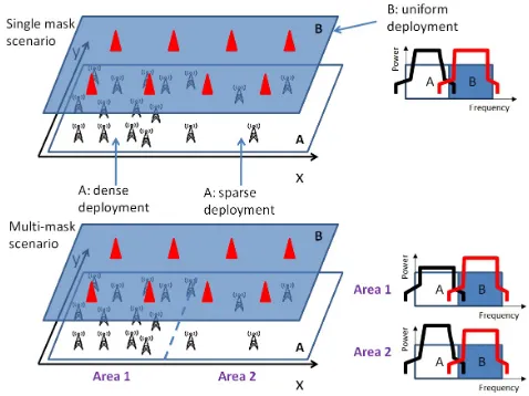
[image:6.595.308.547.164.343.2]that varies with space. When discussing adjacent channel interference we focus on systems using the same geographical area but different frequency bands. It is possible however that over a given geographical area a communication system would exhibit different characteristics such as varying network den-sity. In current regimes oneaverage, or worst-case, spectrum mask would apply. A more dynamic approach may be to use multiple BEMs across the region.
Fig. 9. This figure depicts two networks on adjacent frequencies operating in the same geographical area. Network B exhibits non-homogeneous char-acteristics for which a multi-BEM solution is more spectrally efficient.
Figure 9 attempts to capture this concept. The varying network in Figure 9 could be considered to cover a city area (Area 1) and suburbs (Area 2), the denser deployment being in the city centre. Imagine that Network A is a typical two-way cellular data network and that Network B is a broadcast DVB-H network. The density of the population being served by the DVB-H network does not impact the density of transmitters required as the communication system is a simplex broadcast one, i.e. receiving devices do not transmit back to the bases-tation. However, in the case of the cellular data network the terminal station devices, e.g. phones, do communicate back to the basestation. As such, when the density of terminal devices increases the density of basestations must also increase (where there is no increase in bandwidth) to provide capacity for the increased number of users. In this scenario, increased spectral efficiency across both Area 1 and Area 2 could be achieved if BEMs appropriate to each distinct area were defined.
D. The BEM as a baseline
We can also think of a BEM, whether it be a static, time varying or spatially varying BEM, as a starting point. A starter BEM would perhaps be overly restrictive and subsequent negotiation with neighbours could allow for change in that mask.
more rounded SEM in red shows the SEM after the BEM has been relaxed.
Fig. 10. A Block Edge Mask with two Spectrum Emission Masks: The sculpted SEM conforms to the original BEM, the unsculpted SEM conforms to a relaxed (negotiated) BEM.(Derived from an image that appears in [1])
It is entirely feasible that two spectrally neighbouring com-munication systems would negotiate with each other and come to some agreement about the block-edge. The masks in Figure 10 are symmetrical but of course it is more likely that some kind of asymmetrical BEM would result given that neighbours on each side are more likely to differ. Negotiations could be triggered due to change of use or improvements in technologies on either, or both sides, for example.
E. The Completely Self-generated BEM
The ultimate definition of dynamic, when it comes to a BEM, is a BEM that is self-generating. In this instance networks would somehow be able to perform some sensing and analysis and determine how to coexist; this definition is clearly the most challenging.
It could be possible that a self-organising network comes into existence and initial communication happens over a narrow band of frequencies in the middle of its frequency band. From this initial starting point a mask could be generated by collaborating with its neighbours and determining its impact on the neighbouring networks and vice versa. Figure 11 attempts to capture this concept. In Figure 11 there are some legacy networks that use old-fashioned static BEMs and two newly formed networks which are self-organising.
Figure 11 (b) shows masks that are derived quickly using some kind of minimum coupling loss approach and more accurate masks that take longer to derive are shown in (c) and (d). The latter use more accurate probabilistic analyses to derive more realistic and spectrally efficient BEMs. The main concept being suggested here is one of a progressive process of self-generation of masks. Such a process could lead from cautious initial restrictive assumptions to more relaxed and optimal settings which are based on better (and more complex and time-consuming) calculations and modeling together with actual experience of prevailing conditions.
Fig. 11. This figure depicts a dynamic spectrum access scenario in which there are two vacant channels adjacent to legacy systems. Next generation networks(NGN) must assume a BEM before occupying these channels. A dynamic BEM approach allows the NGNs to be more spectrally efficient as they use better techniques and information to derive the appropriate BEMs.
F. More Potential
[image:7.595.51.282.92.223.2]there may be scope to define dynamic BEMs that incentivize changing (and improving) receiver characteristics. Any system that more fully captures all the costs and benefits of how users access spectrum may help to promote the realisation of market-driven spectrum allocation.
VI. FINDING A BEGINNING INWAPECS
The key question that arises from the discussion thus far is whether it is possible to calculate and derive BEMs that make it possible for any two networks to be neighbours. Recall from Section 1 the effects of adjacent channel interference are complex. The calculation of a BEM for technology and service neutral regimes is still an open research question. However, we have a starting point in that we can look to theWireless Access Policy for Electronic Communications Services(WAPECS) for guidance. WAPECS is a framework for supporting technology and service neutrality that has originated in Europe. And many of the discussion documents relating to WAPECS focus on issues relating to the BEM. The European Commission man-dated theirRadio Spectrum Policy Group(RSPG) to determine the technical goals and scope of the WAPECS project. The RSPG’s conclusions placed an emphasis on technology and service neutrality [9]. In particular the RSPG stated that “For each WAPECS frequency band, provided that the as-sociated electronic communications network complies with the relevant spectrum technical requirements, technological
neutrality and flexibility in future use of the spectrum should be ensured.”
and that
“Any electronic communications service (ECS) may be pro-vided in any WAPECS band over any type of electronic com-munications network. No frequency band should be reserved for the exclusive use of a particular ECS.”
The European Commission then mandated (CEPT) to de-velop such technology and service neutral rules that would advance their goals for specific spectrum bands, [10], [2]. The WAPECS bands cover 470-862 MHz, 880-915 MHz/925-960 MHz, 1710-1785 MHz/1805-1880 MHz, 1900-1980 MHz/2010-2025 MHz/2110-2170 MHz, 2500-2690 MHz and 3.4-3.8 GHz.
WAPECS is not about dynamic BEMs. It is not even about dynamic SEMs. It is of interest here because it contains many ideas that can inform and inspire this discussion; many of the documents which tease out the WAPECS concepts provide a way of thinking through the issues of service and technology neutrality. It makes sense to look at how BEMs are derived within a WAPECS framework, despite the fact that dynamic approaches are not envisaged.
WAPECS introduces two broad andnot-fully-fleshed-out con-cepts which aid in the process of BEM derivation, namely
Network ScenariosandReasonable Expectations. Rather than
think in terms of specific technologies the WAPECS frame-work encourages us to think in terms of netframe-work scenarios. These are required so that it possible to model the interference interaction of different systems when they are placed in adja-cent frequency bands. The network scenarios can be described and compared using a number of characteristics:
• Simplex (broadcasting), duplex (FDD,TDD) communica-tion;
• Point to multi-point (basestation to terminal stations);
• Point-to-point;
• Mesh networks;
• High power/low power;
• Indoor/outdoor receivers;
• Mobile/portable/static receivers;
• Network density;
• Antenna heights (transmitter/receiver).
Reasonable expectations of future receiver performance form an integral part of the WAPECS approach to the definition of rules which will enable technical and service neutrality such that they enable future, unforeseen changes or advances. Among the receiver characteristics that can be considered important in any evaluation are:
• minimum signal level required;
• selectivity;
• susceptibility to co-channel interference.
Changes to any of these parameters may have a significant change on the levels of OOB emissions that can be tolerated in adjacent systems. For example, if the requirements for DVB-T receivers demanded that they had a greater dynamic range, then the receivers could tolerate higher levels of adjacent channel interference which would open up the use of the vacant adjacent channels to higher power uses.
Even though this kind of thinking, from a regulatory perspec-tive, is an advance on prior spectrum management approaches, the notion of reasonable expectations of future performance may not be so important if dynamic BEM generation, in situ, was made possible. In that case, BEMs could be adapted to the prevailing recevier characteristics rather than being designed around forecasted characteristics which may or may not come to pass.
Nonetheless, to arrive at an appropriate BEM for a future system WAPECS suggests a six stage process [10], [2]. For the purposes of our discussion, only 4 of those steps are pertinent: 1) Define the scenarios, i.e. specify the Network Scenario
and Reasonable Future Expectations
2) Derive the BEM by analysing the WAPECS network against the adjacent systems.
4) Analyse the BEM result and have it approved by the relevant authority.
Currently, all of these steps and calculations are performed off-line before the system is in place using a number of different methods.3
The WAPECS framework discusses a number of different techniques for calculating BEMs; two of these are the min-imum coupling loss (MCL) approach and spatio-temporal Monte Carlo (STMC) analysis. The MCL approach is a deterministic one that calculates the minimum adjacent band isolation and minimum propagation loss necessary for a given set of transmitter and receiver parameters. MCL works on the basis that there is an acceptable (or target) receiver desensitisation level [1], [11], [12]. The spatio-temporal Monte Carlo analysis is used for more complex and probabilistic compatibility analysis. The bound on the STMC approach is an acceptable interference probability associated with the service being provided in the adjacent (victim) channel block. Common to both techniques is the use of propagation models appropriate to the frequency and terrain in question.
WAPECS documentation provides examples of BEM calcu-lations for various scenarios. However the scenarios tackled are rather simple and tend to include more traditional com-binations of neighbours such as TDD and FDD neighbours. More complex combinations such as neighbouring high power and low power systems or ad hoc and centralised neighbours or adjacent mesh networks are not considered. As such, the method by which the BEM is calculated is still an open question. Whilst WAPECS focusses on developing the two methods mentioned, there may be other techniques that will be more appropriate to non-traditional network deployments. As mentioned in Section V-E, networks might be able to use a progressive system of BEM calculation that moves using initial conservative techniques to using more advanced techniques that use more sophisticated modeling coupled with empirical evidence. However, this does not detract from the fact that the approach in the WAPECs document provides a framework and a set of steps that suggest that the BEM concept is a feasible one.
VII. CONCLUSION
Talking about spectrum masks in the form of the BEM and SEM components is an approach that allows us investigate the two sides of one problem; namely that of providing a service and technology neutral way of describing and enforcing spec-trum usage obligations. The BEM deals with the derivation of rules and regulations, the SEM deals with the engineering concepts that comply with those rules.
Much of the focus of advanced research into reconfigurable, cognitive, highly adaptive radios concerns allowing radios
3The regulator of the United Kingdom, Ofcom, is using the WAPECS
approach to derive BEMs for its 2.6GHz FDD/TDD allocation of spectrum [4].
to sculpt their spectrum emission profiles. Hence, we are moving from a world in which a SEM was hard-coded into communication devices to a world in which SEMs are generated in situ to suit prevailing conditions. We believe the move towards technology and service neutral spectrum regimes, regimes which are inherently more dynamic and fluid, requires us to think about BEMs in a more dynamic manner. A dynamic BEM allows us to bring ideas from the past that are well understood and accepted into the future. There are indeed many research challenges of a technical nature that need to be addressed to answer many of the questions identified here. However it is essential the regulatory questions be asked in tandem with advances in technology. With that in mind the paper has focused on the WAPECs framework as a starting point for the discussion as it represents a regulatory space in which to begin exploring the concept of future dynamic BEMs for existing dynamic SEMs.
REFERENCES
[1] Electronic Communications Committee (ECC) within the European Conference of Postal and Telecommunications Administrations (CEPT), ”CEPT Report 131: DERIVATION OF A BLOCK EDGE MASK (BEM) FOR TERMINAL STATIONS IN THE 2.6 GHz FREQUENCY BAND (2500-2690 MHz)”, Dublin, January 2009.
[2] Electronic Communications Committee (ECC) within the European Conference of Postal and Telecommunications Administrations (CEPT), ”CEPT Report 19: Report from CEPT to the European Commission in response to the Mandate to develop least restrictive technical conditions for frequency bands addressed in the context of WAPECS”, Report approved on 21 December 2007 with editorial revisions on 17 March 2008 and 30 October 2008.
[3] Electronic Communications Committee (ECC) within the European Conference of Postal and Telecommunications Administrations (CEPT), ”CEPT Report 21: Report A from CEPT to the European Commission in response to the Mandate on: Technical considerations regarding harmonisation options for the Digital Dividend - Compatibility issues between cellular / low power transmitter networks and larger coverage / high power / tower type of networks, Report approved on 30 March 2007.
[4] Office of Communications (Ofcom), ”On the impact of interference from TDD terminal stations to FDD terminal stations in the 2.6GHz band”, 21 April 2008.
[5] G. Bansal, M. J. Hossain, and V. K. Bhargava, Optimal and suboptimal power allocation schemes for ofdm-based cognitive radio systems, Communications, IEEE Transactions on, vol. 7, no. 11, pp. 47104718, 2008.
[6] T. Weiss, J. Hillenbrand, A. Krohn, and F. Jondral, ”Mutual interference in OFDM-based Spectrum Pooling Systems”, in Vehicular Technology Conference, 2004. VTC 2004-Spring. 2004 IEEE 59th, vol. 4, 2004, pp. 1873-1877 Vol.4.
[7] B. Farhang-Boroujeny and R. Kempter, Multicarrier Communication Techniques for Spectrum Sensing and Communication in Cognitive Radios, Communications Magazine, IEEE, vol. 46, no. 4, pp. 8085, 2008.
[8] Federal Communications Commission, Second Report and Order and Memorandum Opinion and Order in the Matter of Unlicensed Operation in the TV Broadcast Bands and Additional Spectrum for Unlicensed Devices Below 900 MHz and in the 3 GHz Band, 14th November 2008. [9] Radio Spectrum Policy Group, ”OPINION ON Wireless Access Policy for Electronic Communications Services (WAPECS) (A more flexible spectrum management approach) FINAL”, November 23, 2005. [10] Information Society and Media Directorate-General of the European
[11] Electronic Communications Committee (ECC) within the Euro-pean Conference of Postal and Telecommunications Administrations (CEPT),”SHARING AND ADJACENT BAND COMPATIBILITY BE-TWEEN UMTS/IMT-2000 IN THE BAND 2500-2690 MHZ AND OTHER SERVICES”, Granada, February 2004.
[12] Electronic Radiocommunications Committee (ERC) within the Euro-pean Conference of Postal and Telecommunications Administrations (CEPT),”A COMPARISON OF THE MINIMUM COUPLING LOSS METHOD, ENHANCED MINIMUM COUPLING LOSS METHOD, AND THE MONTE-CARLO SIMULATION”, Menton, May 1999. [13] Martin B.H. Weiss, ”A Proposal for Efficient Use of the Television