SynOptics Communications, Inc. 4401 Great America Parkway Santa Clara, CA 95054 408-988-2400
April 1994
Installing the Model
© 1994 by SynOptics Communications, Inc. All rights reserved.
Trademarks
SynOptics and SynOptics Communications are registered trademarks of SynOptics
Communications, Inc. Lattis System 5000 is a trademark of SynOptics Communications, Inc.
Other brand and product names are registered trademarks or trademarks of their respective holders.
Statement of Conditions
In the interest of improving internal design, operational function, and/or reliability, SynOptics Communications, Inc. reserves the right to make changes to the products described in this document without notice.
SynOptics Communications, Inc. does not assume any liability that may occur due to the use or application of the product(s) or circuit layout(s) described herein.
Federal Communications Commission (FCC) Statement
Note: This equipment has been tested and found to comply with the limits for a Class A digital device, pursuant to Part 15 of the FCC rules. These limits are designed to provide reasonable protection against harmful interference when the equipment is operated in a commercial environment. This equipment generates, uses, and can radiate radio frequency energy. If it is not installed and used in accordance with the instruction manual, it may cause harmful interference to radio communications. Operation of this equipment in a residential area is likely to cause harmful interference, in which case users will be required to take whatever measures may be necessary to correct the interference at their own expense.
EN 55 022 Declaration of Conformance
This is to certify that the SynOptics Communications Model 5390 Communications Server is shielded against the generation of radio interference in accordance with the application of Council Directive 89/336/EEC, Article 4a. Conformity is declared by the application of EN 55 022:1987 Class B (CISPR 22:1985/BS 6527:1988).
Bestätigung des Herstellers/Importeurs
Es wird hiermit bestätigt, daß das Model 5390 Communications Server gemäß der im BMPT-AmtsblVfg 243/1991 und Vfg 46/1992 aufgeführten Bestimmungen entstört ist. Das vorschriftsmäßige Betreiben einiger Geräte (z.B. Testsender) kann jedoch gewissen
Beschränkungen unterliegen. Lesen Sie dazu bitte die Anmerkungen in der Betriebsanleitung.
Das Bundesamt für Zulassungen in der Telekommunikation wurde davon unterrichtet, daß dieses Gerät auf den Markt gebracht wurde und es ist berechtigt, die Serie auf die Erfüllung der Vorschriften hin zu überprüfen.
Certificate of the Manufacturer/Importer
Federal Office for Telecommunications Approvals has been notified of the placing of this equipment on the market and has been granted the right to test the series for compliance with the regulations.
Compliance with the applicable regulations is dependent upon the use of shielded cables. It is the responsibility of the user to procure the appropriate cables.
Voluntary Control Council for Interference (VCCI) Statement
Voluntary Control Council for Interference (VCCI) Statement
This equipment is in the 1st category (information equipment to be used in commercial and/or industrial areas) and conforms to the standards set by the Voluntary Control Council for Interference by Data Processing Equipment and Electronic Office Machines that are aimed at preventing radio interference in commercial and/or industrial areas.
Consequently, when this equipment is used in a residential area or in an adjacent area thereto, radio interference may be caused to equipment such as radios and TV receivers.
Electromagnetic Emissions
Meets requirements of:
FCC Part 15, Subparts A and B, Class A EN 55 022 (CISPR 22:1985), Class B
Contents
Preface Purpose xiii Audience xiv Conventions xiv
Special Message Formats xiv Two-tiered Procedure Format xiv Use of Enter, Type, and Press xv Other Conventions xv
Related Publications xv
Configuration Support and Technical Assistance xvi
Chapter 1 Overview of the Model 5390 Server Functional Description 17
ROM Monitor Commands 18 Common Management Bus 19
Backplane Ethernet Segment Banks 19 Service Port Management 20
Physical Description 21
Asynchronous Serial Ports 22 LED Displays 23
Annunciator 24 LED Indicators 24
Segment Connection LEDs 24 Module Status LEDs 25 Port Status LEDs 25 Optional Flash Daughterboard 25
Chapter 2 Installing the Model 5390 Server Installing the Software 27
Software Files 28
Preparing for Software Installation 29 Installing the Software on the Host 29
Loading Files Using a UNIX Host 29 Verifying File Installation 30 Loading Files Using a TFTP Host 31
Preparing for Hardware Installation 40 Tools and Equipment 40
Setting the Backplane Ethernet Segment 41 Backplane Ethernet Segment Bank Selector 42 Segment Selection Jumper 42
Installing the Server Module 43 Verifying the Installation 46
LED Indicators 47 Making Connections 48
Serial Devices 49
Chapter 3 Initializing and Configuring the Model 5390 Server
Using a Service Port Terminal 51 Connecting the Terminal 52
Initial Setup and Accessing the Model 5390 Monitor 54 Model 5390 Server Parameters 55
Initializing the Model 5390 Server 56
Automatic Initialization of the Model 5390 Server 58 Downloading the Image Software from a Host System 60
Command Level Interpreter 62 Booting Using BFS 63
Booting Using TFTP 64
Booting from the Flash EEPROM 65 Using SLIP or PPP 68
Configuring Server Ports for Devices 69 Terminals 69
Serial Printer 70 Modems 70
Inbound Modems 70 Outbound Modems 71 Bidirectional Modems 71
Chapter 4 ROM Monitor Commands Command Descriptions 74
addr 75
Examples 76 boot 77
Examples 78 config 81
erase 81 Examples 82 help 82 image 83
Examples 83 ipx 83
lat 83 mop 83 net 84 ping 84 ports 84
Example 85 sequence 85
Examples 86 slip 86
Example 88 stats 88
Example 88
Chapter 5 Troubleshooting Front Panel Indicators 91
Power-up Diagnostic Messages 95 Boot Failures 95
Correcting the Model 5390 Module Parameters 96 Load Server Host Not Responding 97
UNIX Host on the LAN 97 UNIX Host on a SLIP Interface 99 Another Model 5390 Server 99 Conditions for Replacing a Module 100
Module Configuration Management 100 Preparing for a Hot Swap 102
Removing a Module 103 Completing the Hot Swap 103
Appendix A Technical Specifications
Appendix B Host-specific Installation Instructions Tahoe (CCI Power 6/32) 110
ARIX 825 111 ARIX/CMC 112 SCO TCP/IP 114
Siemens MX300 and MX500 118 Concurrent 118
Motorola 88K 118 Prime 119
Figures
Figure 1-1. Model 5390 Communications Server 25 Figure 1-2. Front panel of the Model 5390 server 27 Figure 2-1. Jumper and connector locations 45 Figure 2-2. Inserter/extractor lever 47
Figure 2-3. Inserting the module 48 Figure 2-4. Seating module connectors 49 Figure 2-5. Module LED display 50
Figure 2-6. Connecting devices to the Model 5390 server 52 Figure 3-1. Slot Selection menu 57
Tables
Table 1-1. Annunciator conditions 28 Table 1-2. Module Status LED indicators 29 Table 2-1. Host-resident support utilities 32 Table 2-2. Segment selection jumper settings 46 Table 2-3. RJ-45 port pin assignments 53 Table 2-4. Recommended cable lengths 54 Table 3-1. Service port pin assignments 56 Table 4-1. ROM monitor commands 78 Table 4-2. Slip command prompts 91 Table 4-3. Network statistics 93
Preface
Welcome to the SynOptics® Model 5390 Communications Server. The Model 5390 Communications Server is designed to reside in the Model 5000 chassis produced by SynOptics Communications®, Inc. The Model 5390 server provides asynchronous ports for modem and terminal attachment. Each port provides signals for simultaneous hardware flow control and modem control.
The Model 5390 Communications Server operates in diverse network
environments. The server can communicate with any system that supports the TCP/IP, LAT, and ARA protocols. The Model 5390 server TCP/IP
implementation is derived from the 4.3 BSD distribution of UNIX, as are the implementations of serveral higher-level Internet protocols. The server also supports TN3270 emulation that allows aynchronous personal computers using 3278 emulation to communicate with IBM host computers.
Purpose
This guide describes the Model 5390 Communications Server and its role in the Lattis System 5000™ architecture; explains the installation, connection, and configuration processes; describes the ROM monitor commands; and provides reference information that includes configuration menus, technical
Audience
This guide is intended for network installers or administrators who are responsible for installing, configuring, or maintaining an Ethernet network. These persons are presumed to have the following background:
■ Understanding of Ethernet, Internet Protocol (IP), and network management concepts and terminology
■ Basic understanding of common telecommunication and networking concepts and practices
■ Working familiarity with accepted tools and procedures for installing and operating sensitive electronic equipment
■ Previous contact with SynOptics networking and network management products
Conventions
This section describes the conventions used in this manual.
Special Message Formats
This manual uses the following formats to highlight special messages:
Two-tiered Procedure Format
NOTE:This format is used to highlight information of importance or special interest.
CAUTION:This format is used to highlight information that will help you prevent equipment failure or loss of data.
The procedural steps in this manual are presented in a two-tiered format. The first tier describes the step very briefly, but precisely. An experienced user may only need to read the first tiers to complete the task. The second tier describes the step in more detail and includes results of performing the step.
Use of Enter, Type, and Press
This guide uses enter, type, and press to describe the following actions:
■ When you read “enter,” type the text and press the Enter or Return key.
■ When you read “type,” type the text, but do not press the Enter or Return key.
■ When you read “press,” press only the alphanumeric or named key.
Other Conventions
This manual uses the following typographical conventions:
italics Book titles and UNIX file, command, and directory names.
courier font Screen text, user-typed command-line entries.
Initial Caps Menu titles and window and button names.
[Enter] Named keys in text are shown enclosed in square brackets. The notation [Enter] is used for both the Enter key and the Return key.
[Ctrl]+C Two or more keys that must be pressed simultaneously are shown in text linked with a plus (+) sign.
Related Publications
For more information about using the Model 5390 Communications Server, refer to the following publications:
■ Release Notes for the Model 5390 Communications Server (SynOptics part number 896-050-A) includes changes to the Model 5390
■ Quick Installation for the Model 5390 Communications Server (SynOptics part number 893-737-A) shows you how to quickly set up the Model 5390 Communications Server for operation.
■ Setting Up the Model 5390 Communications Server (SynOptics part number 893-739-A) introduces the Model 5390 Setup utility menus and screens and shows you how to configure basic Model 5390 parameters and serial port parameters.
■ Using the Model 5390 Communications Server (SynOptics part number 893-740-A) introduces the command line interpreter (CLI) for users with terminals connected to the Model 5390 Communications Server.
■ Administering the Model 5390 Communications Server (SynOptics part number 893-741-A) gives instructions for configuring and administering the Model 5390 server software in a network environment.
■ Quick Installation for the Model 5390 Communications Server Flash
Daughterboard (SynOptics part number 893-736-A) shows you how to
install the flash daughterboard EEPROM on the Model 5390 server.
To purchase individual SynOptics product publications, order by part number from SynOptics Press at the following numbers. You may also request a free catalog of SynOptics Press product publications.
■ Phone: 1-800-845-9523
■ FAX: U.S./Canada: 1-800-582-8000, International: 1-916-939-1010
Configuration Support and Technical Assistance
Chapter 1
Overview of the Model 5390 Server
This chapter introduces the Model 5390 Communications Server and covers the following topics:
■ A summary of the Model 5390 server functionality and capabilities
■ A physical description of the Model 5390 server
■ A summary of the Model 5390 front-panel features
Functional Description
The Model 5390 Communications Server is designed to reside in the Model 5000 chassis produced by SynOptics. The Model 5390 server is a product of joint development between SynOptics Communications, Inc. and Xylogics, Incorporated. The Model 5390 server provides 24 asynchronous ports for modem and terminal attachment. Each port is composed of an RJ-45 connector that provides eight signals for simultaneous hardware flow control and modem control. Each port operates at rates up to 115.2 kilobytes per second (KB/s).
The Model 5390 server is a diskless device. The server obtains operational code over the network either from a host running the Model 5390 server or from another Model 5390 server configured as a load server. You can also boot a Model 5390 server from the optional flash EEPROM (self-booting).
The Model 5390 Communications Server features are as follows:
■ Dual 486SLC, 20-MHz processor design. One processor controls the serial ports while the second controls the network data flow and protocol stack.
■ Four megabytes (MB) of dynamic random access memory (DRAM) are standard on the Model 5390 server and can be expanded to 8 MB.
■ The Model 5390 server can boot from a UNIX host, other BootP/TFTP hosts, other Model 5390 servers, and the optional flash read-only memory (ROM) daughterboard resident on the Model 5390 server.
■ Standard Xylogics Annex3 images run on the Model 5390 server so that the normal software release cycles provide an update path for the communications server.
■ The ability to connect the Model 5390 server to any of 12 Ethernet backplane segments.
■ A watchdog timer that the software resets at regular intervals. The watchdog timer reboots the Model 5390 server in the unlikely event of an internal software error. This feature allows the Model 5390 server to run for long periods of time without intervention.
■ The ROM monitor interactive command interpreter accesses the ROM functions.
ROM Monitor Commands
The ROM monitor is an interactive command interpreter that accesses the ROM functions. ROM monitor commands are issued through a terminal connected to the service port on the front panel of the Model 5000 chassis. Using the ROM monitor commands you can:
■ Modify and display a set of EEPROM parameters.
■ Execute interactive diagnostic tests.
■ Receive information and statistics for the hardware configuration and the network.
■ Boot the Model 5390 server manually.
Common Management Bus
The management section of the backplane is the common management bus (CMB), a high-speed, multimaster, shared-memory communication channel that connects all modules installed in the hub to one another and to the
supervisory module. The modules installed in the hub use the CMB to acquire and distribute configuration and status information.
The supervisory module is an intelligent interface between the Model 5000 chassis and user-installed modules. The supervisory module provides the following services to other modules across the CMB:
■ Maintains chassis component information and environmental status
■ Stores the primary module configurations
■ Restores the module configuration after the module power is cycled or the module is reset
The supervisory module also supports configuration terminal support through the service port on the front panel of the chassis.
Backplane Ethernet Segment Banks
The chassis backplane Ethernet bus consists of 12 Ethernet segments, divided into two banks of six segments each: segments 1 through 6 and segments 7 through 12. Each Model 5390 server installed in the chassis can be configured to access one bank of six segments, either segments 1 through 6 or segments 7 through 12.
Service Port Management
The service port, located on the front panel of the chassis, provides a switched serial communication link between the service port and any module in the hub, including the supervisory module. By connecting a terminal to this port, you can change the configuration parameter values for the Model 5390 server installed in the hub.
Physical Description
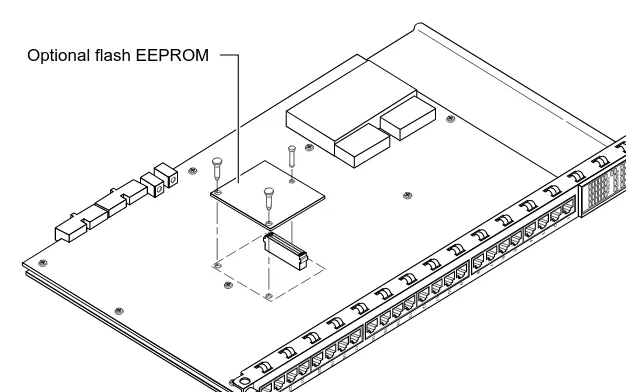
[image:21.612.147.460.196.392.2]The Model 5390 Communications Server (see Figure 1-1) is a mechanical assembly that consists of a metal module frame containing the server baseboard and the plastic front panel. The server can also include an optional flash daughterboard. The assembly includes inserter/extractor levers and captive retaining screws at the top and bottom of the module front panel. The Model 5390 Communications Server occupies a single slot in the Model 5000 chassis.
Figure 1-1. Model 5390 Communications Server
4298
1
2
3
4
5
6
7
8
21
22
23
24
17
18
19
20
13
14
15
16
9
10
11
12
5390
Comm Server
Segment Connection
Port Status
Module Status
Asynchronous Serial Ports
The Model 5390 Communications Server has 24 asynchronous serial ports.
Each port has seven active pins, plus ground, to provide the following standard RS-232 asynchronous signals for modem and flow control:
■ Transmit data (TxD)
■ Receive data (RxD)
■ Data terminal ready (DTR)
■ Clear to send (CTS)
■ Data set ready (DSR)
■ Request to send (RTS)
■ Carrier detect (DCD)
LED Displays
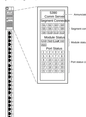
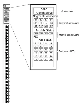
[image:23.612.145.445.124.533.2]The Model 5390 server has an LED display located near the top of the front panel (see Figure 1-2).
Figure 1-2. Front panel of the Model 5390 server
1 2 3 4 5 6 7 8 9 10 11 12 13 14 15 16 17 18 19 20 5390 Comm Server Segment Connection Port Status Module Status 21 22 23 24 4297 Annunciator
Segment connection LEDs
Port status LEDs
Port 24
Module status LEDs
5390 Comm Server Segment Connection Port Status Module Status S4 S3 S2 S1 S8 S7 S6 S5 S12 S11 S10 S9 1 5 9 13 17 2 6 10 14 18 3 7 11 15 19 4 8 12 16 20 21 22 23 24 Net Load Init Unit
The LED display is an intelligent display consisting of two major elements: a single, bicolor LED (displaying in either green or amber) referred to as the “annunciator,” and a 4-column by 11-row matrix of bicolor LEDs (displaying in either green or amber).
Annunciator
When power to the module is on and within the appropriate range, the annunciator (see Figure 1-2) backlights the model number of the module and indicates−by its color−the operational condition of the module (see Table 1-1).
.
LED Indicators
The LED indicators on the Model 5390 server front panel are arranged in three groups:
■ Segment Connection
■ Module Status
■ Port Status
Segment Connection LEDs
The Segment Connection LEDs consist of one group of 12 LEDs, labeled S1 through S12. These 12 LEDs indicate whether a particular backplane Ethernet LAN segment is being used by the Model 5390 server. A steady green Segment Usage LED indicates that the Model 5390 server is connected to that backplane Ethernet LAN segment; otherwise, the LED is off.
Table 1-1. Annunciator conditions
Color Condition
Green The module is performing normally.
Amber Some portion of the module has failed, or the module is being initialized.
Module Status LEDs
The Module Status LEDs are a group of five indicators. They display the status of the activity of the Model 5390 server (see Table 1-2).
.
Port Status LEDs
The Port Status indicators are numbered 1 through 24. They display serial port configuration status during normal operations. All the server ports are
configured at the factory, therefore, all the indicators turn green when the module is booted for the first time. If an error condition exists for a configured port, the LED turns amber. A port status LED remains turned off, if the port is not configured for use.
Optional Flash Daughterboard
The Model 5390 server has an optional flash daughterboard that attaches to the baseboard. The flash daughterboard allows the communications server to boot without using a load server. Figure 1-1 illustrates how the flash daughterboard is oriented on the Model 5390 baseboard.
Table 1-2. Module Status LED indicators
LED Description
Init Turns green when the Model 5390 server begins the initialization process after a power-up or reset. This is the first LED that lights after power-up or reset. The Init LED turns off after the diagnostics have successfully completed.
Unit Turns green after the Model 5390 server passes the power-up diagnostics. Turns amber if the power-up diagnostics fail.
Net Turns green after the Model 5390 server verifies that a valid Ethernet connection exists.
Attn Turns amber when the Model 5390 server requires operator attention, that is, in monitor mode or when the diagnostic tests fail.
Load Turns green when the Model 5390 server is loading the operational image
Chapter 2
Installing the Model 5390 Server
This chapter outlines the procedures for installing the Model 5390 Communications Server software, preparing the server for installation, installing it, and verifying that it is operating correctly.
This chapter includes the following information and procedures:
■ Software files
■ Preparing for software installation
■ Installing the software on the host
■ Setting up the host server
■ Equipment you need to install the module
■ Locating and setting jumpers
■ Verifying the installation
■ Making connections
Installing the Software
Before you install the Model 5390 module, prepare the host system by installing the Model 5390 Communications Server software. This section contains procedures for installing the software on a host. Chapter 3,
“Initializing and Configuring the Model 5390 Server,” contains procedures for downloading the necessary files to the Model 5390 Communications Server.
Software Files
The distribution tape contains two types of files:
■ One type resides on the Model 5390 server and is downloaded from the installation host.
■ Another type resides on the host and requires a UNIX host with a C compiler and TCP/IP network protocols on which to compile and execute.
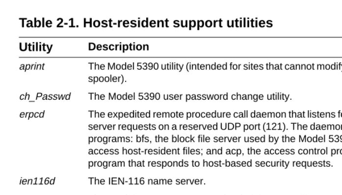
[image:28.612.157.506.269.467.2]The distribution tape contains the Model 5390 operational code and host-resident Model 5390 support tools. The tools are distributed in C language source form with appropriate make files. The Model 5390 operational code is already built. The host-resident Model 5390 support utilities are listed in Table 2-1.
Table 2-1. Host-resident support utilities
Utility Description
aprint The Model 5390 utility (intended for sites that cannot modify the Berkeley spooler).
ch_Passwd The Model 5390 user password change utility.
erpcd The expedited remote procedure call daemon that listens for Model 5390
server requests on a reserved UDP port (121). The daemon contains two programs: bfs, the block file server used by the Model 5390 server to access host-resident files; and acp, the access control protocol (ACP) program that responds to host-based security requests.
ien116d The IEN-116 name server.
na The Model 5390 server network administrator utility.
rtelnet A pseudo-tty device creations utility that allows such UNIX programs as tip and uucp to access serial devices attached to Model 5390 ports.
Preparing for Software Installation
To prepare to install the Model 5390 server software, follow these steps:
1. Select the directory that will serve as the root of the Model 5390
source tree. The /usr/5390 directory is assumed to be the default.
The directory requires approximately 3 MB of memory to read the tape and approximately twice this amount to build the programs.
2. If you intend to install the host-resident Model 5390 software tools,
select the directory that will contain the compiled Model 5390 tools.
The Model 5390 server installation procedures use the /annex directory in the examples.
The directory requires approximately .5 MB of memory.
3. Select the directory in which the boot images and dump files will be
stored.
The /usr/spool/erpcd/bfs directory is assumed to be the default.
The directory you select will require 2.5 MB of free storage space for the boot images and 1 to 3 MB for dump files for each Model 5390 server serviced by this file server.
Installing the Software on the Host
This section provides procedures to download files using a UNIX host or a non-UNIX host. After you download files using a non-UNIX host, perform the
procedure to run the installation script.
Loading Files Using a UNIX Host
To install the software for the Model 5390 server on a UNIX-compatible host, follow these steps:
1. Insert the distribution tape into the tape drive.
2. Become a superuser on your host system by entering the following command at the prompt:
su
3. Enter the password at the password prompt.
4. Create a directory to serve as the root of the Model 5390 software tree,
if it does not already exist, by entering the following command at the UNIX prompt:
mkdir /usr/annex
5. Change to the new directory by entering the following command:
cd /usr/annex
6. Extract the contents from the distribution tape by entering the
following command (device_name is the device from which you are loading):
tar -xvf /dev/device_name
If, on your system, you cannot use the tar command to create directories, first make sure you are in the directory into which you want to load the files, and then enter the following commands:
tar -xvf /dev/device_name extract-it
extract-it /dev/device_name
Verifying File Installation
To verify that all the files on the distribution tape have been extracted, follow these steps:
1. Enter the following command:
tar -xvf /dev/device_name > 5390.files
2. Compare the list of files to the files on the tape to verify that all the
Loading Files Using a TFTP Host
To load the software from a host that is not UNIX-compatible or if you choose to use TFTP, follow these steps:
1. Insert the distribution tape into the tape drive.
2. Load files from the bfs directory (in your annex directory) to your tftp
directory by entering the following command:
cp bfs/* /tftpboot/annex/
3. Create any other necessary download files (config.annex, motd) in the
same tftp directory.
To expedite the download, create empty download files for those that you do not need.
Go to “Installing the Communications Server” later in this chapter.
Running the Installation Script on a UNIX Host
Running the install-annex script generates a configuration of your system and installs the Model 5390 server host utilities and man pages. Any prompt that has a default displays it in brackets. Press [Enter] to choose the default.
The configuration sequence of the installation script generates two files:
■ src/Makefile
■ src/make.config
These files compile and install the Model 5390 tools.
To run the install-annex script, follow these steps:
NOTE:Make sure that TFTP is running on your host. This protocol is not supplied with the Model 5390 software.
1. Enter the following command:
./install-annex
The installation script is displayed, similar to the following example:
Annex-UX R8.0 Host Utilities Installation Script
*********************************************************************** **It is recommended that you run this install-annex script as root.** ***********************************************************************
This installation shell script will examine your system and possibly ask you questions to generate the needed configuration to allow you to compile the annex host utilities.
You can abort the script at any time and restart it without any ill effects.
Once install-annex completes the configuration section, you will only need to use
"make all" and "make install"
from the "src" directory to later re-build or re-install the utilities. At any question prompt you can escape to a shell by typing "!".
When you exit that shell you will bounce back to the question prompt. Many of the questions will have default answers in square brackets; typing carriage return will give you the default.
Type carriage return to continue. Your cursor should be here--> [Enter]
2. Press [Enter] to continue the installation script.
Text is displayed similar to the following example:
Beginning configuration. Locating common programs... ar is in /bin/ar.
awk in /bin/awk. cat is in /bin/cat. cc is in /usr/ucb/cc. chown is in /usr/etc/chown. chmod is in /bin/chmod. cp is in /bin/cp. date is in /bin/date. echo is in /bin/echo. expr is in /bin/expr. grep is in /bin/grep. mkdir is in /bin/mkdir. mv is in /bin/vm.
ranlib is in /bin/ranlib. rm is in /bin/rm.
sed is in /bin/sed.
Don’t worry if any of the following aren’t found... inetd is in /usr/etc/inetd.
The installation script prompts you for the machine type and operating system of the host.
Select the most appropriate machine type
1.Sun 10.Hewlett Packard
2.Encore 90 Family or Multimax 11.Decstation (ULTRIX)
3.UNISYS 12.MIPS
4.UNISYS S Series CTIX 13.Silicon Graphics
5.NCR 14.SCO UNIX
6.Pyramid 15.AT&T Star Server FT
7.Sequent PTX 16.Interactive UNIX
8.Sequent Dynix 17.ICL DRX/6000
9.IBM RS/6000 (AIX) 18.OG AViiON (DG/UX)
0.Generic (no special code needed or machine not listed
Enter Machine Type #:
3. Select the machine type of the host on which you are installing the
software.
If your machine is not listed in the menu, refer to Appendix B, “Host-specific Installation Instructions,” for more details. Otherwise, choose generic.
When you choose generic, the script prompts you for the type of operating system.
Select the most appropriate OS
1. 4. [23]BSD UNIX (& UMAX BSD) 2.System V UNIX (& UMAX V) 3. XENIX System V
4. MACH 5. SVR$
Enter OS #:
NOTE:If cc is not found, stop. You must install a compiler on your system before continuing, or boot using TFTP. If your compiler is not in the standard directory, edit the install-annex script to add the compiler directory to the pth variable.
4. Enter the number of the operating system you are using.
If you select SYS_V UNIX, the script requests the following information:
Does your system have any auxiliary libraries for the network code? [n]:
If you answer yes, you are prompted with the following question:
Enter any additional loader options for the network libraries.
(ex: "-lnet" or ’-lsocket") Loader options:
Does your system have any alternate include directory for network code? [n]:
If you answer yes, you are prompted with the following question:
Where are the network include files located?
5. Enter the directory name where the network include files are located.
The script prompts you for the network software package:
What kind of Network Software does your OS have?
1. 4. [234]BSD or compatible 2. Excelan EXOS package 3. CMC package
4. Wollongong WINS package
5. None. Use user-level SLIP (SysV/XENIX only) 6. TLI. Transport Layer Interface
Enter Net S/W Type #:
6. Enter the number of the network software package, if you have more
than one network software package installed.
NOTE:If you chose from the machine-type menu and your host has only one OS, you will not be prompted for operating system type.
After you answer these questions, the script verifies that the desired functions are installed on your system and the following text is displayed:
Checking your system for these features... #include <sys/types.h> ok
#include <netinet/in.h> ok bcopy () ok
bzero () ok dup2 () ok
gethostbyname () ok gethostbyaddr () ok gethostname () ok getservbyname () ok hton1 () ok
htons () ok ntoh1 () ok ntohs () ok inet_addr () ok inet_ntoa () ok recvfrom () ok recvmsg () ok sendmsg () ok sendto () ok index ok rindex ok select ok u_char ok u_short ok u-long ok hostent ok servent ok
If a function is not found, one of the following messages displays next to the missing function:
not found, adding
or
The script asks where to install the Model 5390 utilities, download files, and man pages.
Where do you want the 5390 utilities installed? [/usr/annex]
[Enter]
Select a directory for the 5390 operational images and boot files.
BFS directory name [/usr/spool/erpcd/bfs]: [Enter]
Do you want to install manual pages at this time? [n]: [Enter]
What kind of on-line manual page layout do you have? Select the most appropriate on-line manual page layout:
1. v7/BSD (/usr/man/man?)
2. SystemV (/usr/{catman,man}/[apu]_man/man?)
3. None (don’t install on-line manual pages automatically)
Enter on-line manual page type #: [1] [Enter]
You have several location options for installing man pages, based on the type of system you have; you also have the option of not installing man pages.
If you select number 1 from this menu, to install the man pages using BSD page layout, you are asked for the directories in which these manual pages reside:
How should the on-line manual pages be installed?
1. One directory (i.e., under /usr/man/man1)
2. Multiple directories (i.e., under /usr/man in man1, man5, man8)
Enter on-line manual page layout type [1] [Enter]
If you select number 1 from this menu, to install man pages in one directory, you are asked the following questions:
How are manual page extensions handled in /usr/man/man1?
1. They use a fixed extension like ".1" 2. They use the extension of the manual page
(i.e., ".1", ".5", ".8" - note that this is not typical)
Enter manual page extension type: [1] [Enter]
What is the extension used? [1] [Enter]
If you select number 2 from the same menu, to install the man pages in multiple directories, you are prompted by the following question:
What directory should be used/ [/usr/man/man1] [Enter]
Whatever manner you choose to install the man pages, the following display indicates that the configuration portion of the script is complete:
Executing "du -s bin/[A-Z]*"
1454 bin/IUNIX
1228 bin/SCO
1026 bin/SOL2
810 bin/SUN
To save room on your system, the above directories can be removed. They contain the pre-compiled binary images for the various host-based utilities. Since this installation will not be making use of these files, it should now be safe to remove them. However, if you do choose to remove these directories, you should know that you will not be able to re-run the script for a binary install. (You can always restore from the distribution kit if you need to do a binary installation.)
Remove these directories? [Y/N]: [Enter]
Creating configuration files...complete.
The script prompts you to compile and install the Model 5390 tools:
Shall I compile the tools for you? [y]: [Enter]
If you answer y, the following text is displayed:
Compiling the tools; output being saved in "Build.out"
*** Building libannex *** *** Building netadm *** *** Building na *** *** Building erpcd *** *** Building ien-116 *** *** Building timserver *** *** Building rtelnet *** *** Building aprint ***
Shall I install the tools for you? [y] [Enter]
If you are running as root and you answer y to the question, the following text is displayed:
Installing the tools; output being save in "Install.out"
*** Installing Annex-UX R8.0 images *** *** Installing manual pages ***
*** Installing libannex *** *** Installing netadm *** *** Installing na *** *** Installing erpcd *** *** Installing ien-116 *** *** Installing timserver *** *** Installing rtelnet *** *** Installing aprint ***
Done.
If you did not compile and install the tools, the following text is displayed:
Installation not completed.
To compile the tools use "cd src ; make"
To install the tools and manual pages use "cd src ; make install"
Done.
At this point the software installation procedure is complete. If you need to rebuild or reinstall the Model 5390 software in the future, you need to run only the make and make install scripts from the src directory.
Setting Up the Host Server
Before you install the Model 5390 server and download the software to it, you need to make the following edits to the host files.
To edit the host files, follow these steps:
1. Use vi to add the following line to the /etc/services file that defines a
UDP port for the erpcd daemon.
erpc 121/udp # annex erpc listener
2. Change your default directory to where the host tools are installed (the default is the /usr/annex directory) by entering the following command:
cd /usr/annex
3. Log in as root and start the erpcd daemon by entering the following
command:
./erpcd
The erpcd daemon is located in the directory where you installed the Model 5390 utilities.
As a daemon, erpcd detaches itself and returns your terminal to the UNIX shell. To verify that the erpcd daemon is running on UNIX System V systems, enter the following command:
ps -ef | grep erpcd
You can verify that the erpcd daemon is running on Berkeley UNIX systems by entering the following command:
ps -aux | grep erpcd
4. Update your rc file to start the erpcd daemon when the system is
booted. Use vi to edit the file.
For UNIX System V systems make sure the network daemons are started first, then update your tcp start-up file in rc2.d by adding the following lines:
if [ -f /annex-directory/erpcd ]; then
/annex-directory/erpcd & (echo -n ’erpcd’) > /dev/console fi
For Berkeley UNIX systems, add these lines to the rc.local file
.
Additional host set-up procedures may involve name and time servers. Refer to
Administering the Model 5390 Communications Server for information about
various set-up procedures.
After the Model 5390 software is loaded on the file server host, install the hardware.
Installing the Communications Server
Installing the Model 5390 server involves seating the backplane connectors to the Model 5000 chassis backplane, verifying the installation, and connecting devices.
Preparing for Hardware Installation
This section explains how to prepare the Model 5390 server for installation in the chassis.
Tools and Equipment
To connect and power up the Model 5390 server, you need the following tools and equipment:
■ A 3/16-inch flat-tip screwdriver
■ An antistatic mat and wrist strap (attached to an antistatic leash)
■ The service port cable and a terminal
Setting the Backplane Ethernet Segment
Figure 2-1 shows the locations of the configuration jumpers on the Model 5390 Communications Server. There are two sets of jumpers that you set:
■ Backplane Ethernet segment bank selector (J6, J7, J8)
[image:41.612.162.487.348.558.2]■ Backplane Ethernet segment selection jumper (J1).
Figure 2-1. Jumper and connector locations
CAUTION:System 5000 equipment uses electronic components that are sensitive to static electricity. Static discharge from your clothing or other fixtures around you can damage these components. You should take all possible precautions to prevent static discharge damage when working with printed circuit boards.
If possible, place all printed circuit boards on an antistatic mat until you are ready to install them. If you do not have an antistatic mat, wear a discharge leash to free yourself of static before touching any of the printed circuit boards, or free yourself of static by touching the metal of the chassis before handling a printed circuit card.
J6 J7 J8
J11
J1 1,7 2,8 3,9 4,10 5,11 6,12
4295
Backplane segment bank selector
Flash daughterboard
Segment selection pins
S1 - S6
S7 - S12 or
Backplane Ethernet Segment Bank Selector
The segment bank selector (see Figure 2-1), consisting of three rows of 30 pins (J6, J7, J8) and a gang jumper, determines whether the module connects to backplane Ethernet segments 1 through 6 or segments 7 through 12 at power up. When the gang jumper is installed between J6 and J7, the module has access to segments 1 through 6; when the gang jumper is installed between J7 and J8, the module has access to segments 7 through 12.
The specific segment connection for the Model 5390 server is determined by the segment selection jumper (described in “Segment Selection Jumper” later in this chapter).
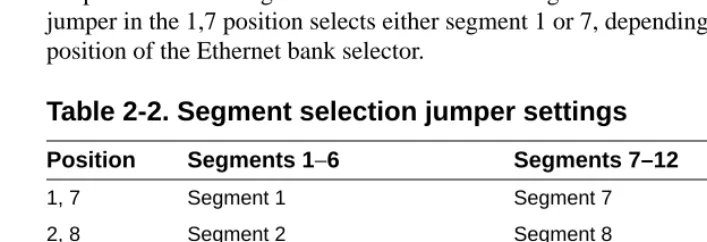
Segment Selection Jumper
J1 (see Figure 2-1) is a 12-pin header used to set the default segment selections. Segment selection jumper settings are listed in Table 2-2. Placing a jumper on the pins selects the segment within the Ethernet segment bank For example, a jumper in the 1,7 position selects either segment 1 or 7, depending on the position of the Ethernet bank selector.
NOTE:When the segment bank selector is installed between J6 and J7, the printed circuit card handle is nearest the backplane edge of the Model 5390 server. To install the jumper between J7 and J8, remove the jumper, rotate it 180° (so that the printed circuit card handle is nearest the front-panel edge of the Model 5390 server) and push it onto the pins of J7 and J8.
[image:42.612.153.507.475.596.2]NOTE:Network management software cannot override the bank selector setting. The setting (segments 1–6 or 7–12) can only be set while the module is outside the chassis.
Table 2-2. Segment selection jumper settings
Position Segments 1−6 Segments 7–12
1, 7 Segment 1 Segment 7
2, 8 Segment 2 Segment 8
3, 9 Segment 3 Segment 9
4, 10 Segment 4 Segment 10
5, 11 Segment 5 Segment 11
Installing the Server Module
To install and secure the module in the chassis, follow these steps:
1. Remove the blank filler panel from the chassis slot where you intend
to install the module.
2. Verify that the module jumpers are set correctly, as described in
“Setting the Backplane Ethernet Segment” earlier in this chapter.
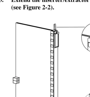
3. Extend the inserter/extractor levers to their fully extended positions
[image:43.612.166.344.281.473.2](see Figure 2-2).
Figure 2-2. Inserter/extractor lever
NOTE:Network management software can override this jumper setting, so an installed module might connect to a different segment (within the bank) than is indicated by the jumper setting.
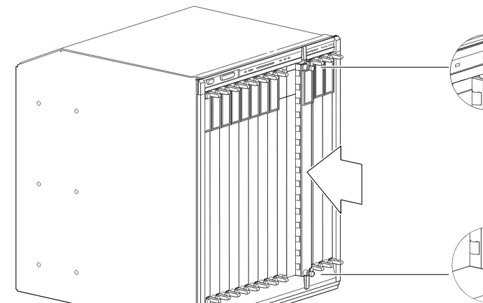
4. Align the top and bottom edges of the module in the card guides of the target slot, and push the module into the chassis until the inserter/ extractor levers just engage the front edges of the chassis (see Figure 2-3).
Figure 2-3. Inserting the module
Model 5000
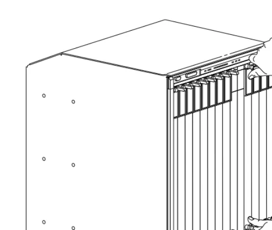
5. Seat the module backplane connectors by simultaneously pushing the inserter/extractor levers toward the center of the module front panel (see Figure 2-4).
Figure 2-4. Seating module connectors
When the front panel of the module is flush with the front of the chassis, the module backplane connectors are properly seated.
6. Use the flat-tip screwdriver to tighten the captive retaining screws
at both ends of the module front panel.
NOTE:The captive retaining screws on the module must be
tightened to at least 4 inch-pounds, but no more than 8 inch-pounds of torque.
Model 5000
Verifying the Installation
After installing and connecting the Model 5390 server, verify that you have performed the installation correctly by observing the LED indicators and system operation displays on the front panel of the Model 5390 server (see Figure 2-5).
[image:46.612.154.457.164.561.2].
Figure 2-5. Module LED display
1 2 3 4 5 6 7 8 9 10 11 12 13 14 15 16 17 18 19 20 5390 Comm Server Segment Connection Port Status Module Status 21 22 23 24 4297 Annunciator
Segment connection LEDs
Port status LEDs
Port 24
Module status LEDs
5390 Comm Server Segment Connection Port Status Module Status S4 S3 S2 S1 S8 S7 S6 S5 S12 S11 S10 S9 1 5 9 13 17 2 6 10 14 18 3 7 11 15 19 4 8 12 16 20 21 22 23 24 Net Load Init Unit
LED Indicators
When the Model 5390 server is operating correctly, the front-panel LEDs (see Figure 2-5) should appear as follows:
■ Annunciator: The annunciator should be green after the Model 5390 server successfully completes the self-tests.
■ Segment Connection LEDs: A steady green indicates which Ethernet LAN segment the module is using.
■ Module Status LEDs:
– Init: Turns green when the Model 5390 server begins the initialization process after a power-up or reset. Typically, this is the first LED that lights after power-up. The Init LED turns off after the initial
diagnostics have successfully completed.
– Unit: Turns green after the Model 5390 server passes the power-up diagnostics.
– Net: Turns green after the Model 5390 server verifies that a valid Ethernet connection exists.
– Attn: The attention LED should be off. Turns amber if the Model 5390 server is in monitor mode.
– Load: Turns green when the Model 5390 server is loading the operational image or dumping a RAM image if there is a failure.
■ Port Status LEDs: All the port status indicators turn green.
■ Verify that the hub front-panel LEDs are properly illuminated.
If the Model 5390 server LEDs do not light in the proper manner, or if the system operation displays indicate problems, refer to Chapter 5,
“Troubleshooting,” for additional information.
NOTE:The Model 5390 server performs a series of self-test diagnostics each time the Model 5390 server is reset or powered up. These tests take about 30 seconds to complete and cannot be deactivated. While these tests are running, the annunciator remains amber. For information about possible error
Making Connections
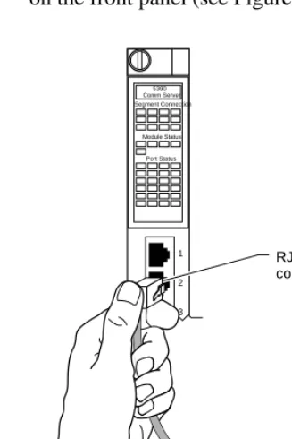
The Model 5390 server has 24 asynchronous ports that you can use for modem, serial printers, ISDN terminal adapter (TA), and terminal attachment. The connectors are RJ-45 with RS-232 signaling.
[image:48.612.160.324.188.433.2]To connect devices to the Model 5390 server, plug the connectors into the ports on the front panel (see Figure 2-4).
Figure 2-6. Connecting devices to the Model 5390 server
For information about how to configure modems for the Model 5390 server see “Configuring Server Ports for Devices” in Chapter 3, “Initializing and Configuring the Model 5390 Server.”
1
2
3
4
5
6
7
8
RJ-45 connector
STP or UTP patch cable
5390 Comm Server Segment Connection
Port Status Module Status
Table 2-3 lists the RJ-45 port pin assignments.
You do not have to connect serial devices to install the Model 5390 server; however, you must connect a terminal to the service port before setting up and booting the Model 5390 server. To connect a terminal to the service port, see “Using a Service Port Terminal” Chapter 3, “Initializing and Configuring the Model 5390 Server.”
Serial Devices
[image:49.612.145.447.117.241.2]The Model 5390 server user ports conform to the RS-232 signaling specification. However, it is possible to exceed the cable limits of the specifications given good-quality cables that are run in an electrically quiet environment and grounded at one end only. SynOptics only guarantees operation with cables that conform to the appropriate specification. Table 2-4 lists the recommended cable lengths.
Table 2-3. RJ-45 port pin assignments
Pin # Signal name Direction
1 RTS Out
2 DTR Out
3 TXD Out
4 DCD In
5 RXD In
6 GND
7 DSR In
8 CTS In
CAUTION:The Model 5390 server can incur damage if the cables conduct such transients as those caused by lightning strikes.
1
RJ-45
8
RS-423 drivers and receivers are used on the data lines (TxD and RxD) to increase the signaling distances. Use Table 2-4 as a guide for determining the maximum cable length versus data rate.
Table 2-4. Recommended cable lengths
Data rate Maximum cable length:
feet
Maximum cable length: meters
19,200 and below 250 76
38,400 200 60
57,600 100 30
Chapter 3
Initializing and Configuring the
Model 5390 Server
This chapter describes how to set up, configure, and download the operational software to the Model 5390 Communications Server.
This chapter includes the following information:
■ Connecting a terminal to the chassis service port
■ Connecting to the Model 5000 chassis and entering monitor mode
■ Automatically initializing the server
■ Downloading the image software
■ Booting from the flash EEPROM
Using a Service Port Terminal
If your network does not include a BootP server, you must connect a terminal to the service port on the chassis front panel and manually configure the Model 5390 server so that it can then use TFTP to acquire its configuration and image files.
To configure the Model 5390 server through the chassis service port, you need:
■ A TTY-compatible terminal or a portable computer with a serial port and the ability to emulate a TTY-compatible terminal. The terminal should be set up for:
– 9600 b/s (default)
– 8 data bits
– No parity
– 1 stop bit
– No handshaking
■ An RS-232 modem cable with a female DB-9 connector to connect to the service port on the chassis front panel. The other end of the cable must have a connector appropriate to the serial port on your computer or terminal. (Most terminals or computers use a male DB-9 or DB-25 connector.) The cable should use the pin assignments in Table 3-1.
Connecting the Terminal
To connect the terminal to the service port, follow these steps:
1. Connect the terminal (or a computer in terminal emulation mode) to
the chassis service port with the RS-232 cable described earlier in this section.
2. Set the terminal protocol as described earlier in this section.
3. Turn on the terminal; adjust contrast and brightness as required.
4. Press [Enter] or [Ctrl]+T to display the Slot Selection menu.
The Slot Selection menu (Figure 3-1) shows the system date and time, lists the modules installed in the chassis by slot number, and lists the available commands.
Table 3-1. Service port pin assignments
Terminal Function To service port Function
DB-9 pins
DB-25 pins
DB-9 pins
2 3 Receive data 2 Transmit data
3 2 Transmit data 3 Receive data
5 7 Signal ground 5 Signal ground
Figure 3-1. Slot Selection menu
Use this menu to reset the Model 5390 server. For more information, see “Initializing the Model 5390 Server” later in this chapter.
Model 5000 Slot Selection Menu
Slot 1 1 2 3 4 5 6 7 8 9 10 11 12 13 14
c - Connect to slot [Press CTRL-T to break connection] s - Select Supervisory Module Main Menu
Enter Selection: Status: On-line Configuring Other (removed) Off-line Booting On-line Off-line
Module Description: 5310 Ethernet NMM 5308 Ethernet Host 5308 Ethernet Host 5308 Ethernet Host 5308 Ethernet Host 5308 Ethernet Host 5308 Ethernet Host 5390 Comm Server
r - Reset module 07/07/93, 12:53:32 PM
Initial Setup and Accessing the Model 5390 Monitor
After installing the Model 5390 software on the file server host (refer to Chapter 2, “Installing the Model 5390 Server” for procedures to install the software), collect the following information, which is required to determine the Model 5390 boot parameters:
■ Where are the download files on the host (tftp only)?
■ Are the Model 5390 server and host on the same subnet or are they separated by a gateway?
■ Are the Model 5390 server and the host connected by serial ports using the Serial Line Internet Protocol (SLIP)?
■ Is the host going to use tftp or erpcd (requires a UNIX host) to serve the Model 5390 download code.
The Model 5390 server needs these parameters to perform an initial boot when loading the software. Enter these parameters into the Model 5390 EEPROM using the ROM monitor commands, which are accessed through the service port terminal. For more information about these commands refer to Chapter 4, “ROM Monitor Commands.”
The Model 5390 server supports the Bootstrap Protocol (BootP) and the Reverse Address Resolution Protocol (RARP) which can be used to obtain some of the information listed. If you have a host running BootP or RARP to serve the Model 5390 server the information, the server will boot without user intervention. For more information about using these protocols, see “Automatic Initialization of the Model 5390 Server” later in this chapter.
Model 5390 Server Parameters
The Model 5390 Communications Server requires that certain parameters be set by the ROM monitor before it can boot from a host. Once the Model 5390 server is booted, you can change these parameters using the Model 5390 server
na utility or the command level interpreter (CLI) command, admin. These
parameters are explained in Administering the Model 5930 Communications
Server. A brief description of these parameters follows:
Internet address: A unique 32-bit universal identifier that is specified in dotted-decimal notation.
Subnet mask: Defines which portion of the Internet address is the network (all ones), the subnet (all ones), and the host (all zeros) address.
Preferred load host address: The Internet address of the host from which you want to boot.
Load/dump gateway Internet address:
The Internet address of the gateway, for which you will be prompted, if the preferred load host is on a different network.
Broadcast address: An Internet address with a host id of all ones or all zeros (for 4.2 BSD) to which all hosts on a particular network will respond.
Initializing the Model 5390 Server
This section describes how to set up the Model 5390 server, make the
connection to the System 5000 hub for the first time, and enter monitor mode to configure the module.
To initialize the Model 5390 server and enter monitor mode, follow these steps:
1. Use a terminal connected to the chassis service port to verify that the
Model 5390 server is operating properly.
The Slot Selection menu is displayed. The Model 5390 Communications Server should be listed next to the slot number in which it is installed.
2. Reset the Model 5390 server by typing r and then entering the slot
number of the chassis that contains the server.
The following prompt is displayed:
Are you sure you want to RESET this module? (Y/N):
3. Answer the question by entering y.
4. Within 10 seconds, connect to the Model 5390 server by typing c and
then entering the slot number of the chassis that contains the server.
5. Wait for the following prompt:
To enter “Monitor Mode” please depress the SPACE key within 10 seconds.
The prompt counts down from 10 seconds.
6. Press the space bar within 10 seconds.
After a few seconds, the following messages are displayed:
Monitor Mode selected, please wait for Confidence tests to complete.
System Reset - Entering Monitor Mode
Then the monitor prompt is displayed:
monitor::
7. Verify the Model 5390 server hardware configuration by entering the following command at the monitor prompt:
config
The following text is displayed:
ROM Software Rev #
Board ID: Serial Number
Memory size: 4 Meg
Flash Size: Flash ID:
EEPROM size:
Total number of ports: 24
ASYNC Config
Number of ports: 24
Max Port speed: 115.2 Kbps Hub Config
Slot Position: CMB HW Revision: EEPROM Revision:
Jumper Segment Selection: EEPROM Segment Selection:
8. To verify and record the Model 5390 Ethernet address for future
reference, enter the following command at the monitor prompt:
addr –d
The following information is displayed:
Ethernet address (hex): 00-80-2D-00-18-B6 Internet address: <invalid or uninitialized> Subnet mask: <invalid or uninitialized> Preferred load host address: <any host> Broadcast address: 0.0.0.0
9. Verify that the Model 5390 server is online by entering the following command:
net
Enter Segment to be used [1]:
A “pass” or “fail” message is displayed. If fail is displayed, try verifying the network from another device.
Once the Model 5390 server is online, you can download the image software to the server. See “Downloading the Image Software from a Host System” later in this chapter.
Automatic Initialization of the Model 5390 Server
The Model 5390 server supports BootP and RARP. The ROMs use these protocols to obtain boot information without requiring any manual setup on the Model 5390 server.
■ BootP allows a diskless client to determine its Internet address, the Internet address of the server, and the name of the file to be loaded into memory.
■ RARP maps a hardware address into an Internet address.
The ROMs invoke this system of acquiring boot information when a boot is initiated and the Model 5390 server Internet address is not initialized. Under this condition, the Model 5390 server first tries to get boot information via BootP; if BootP fails, it tries to get boot information via RARP. If neither protocol is successful, the Model 5390 server either prompts the user for the Internet address (if in monitor mode) or it flashes the Attn and Load LEDs to indicate the Internet address is not set (if in normal mode).
5390default:\
:sm=255.255.255.0:gw=132.245.22.66:\
:hn:vm=auto:to=-18000:
terminator:ht=1:ha=00802d004879:ip=132.245.22.226:tc=5390default
:
In this example:
■ sm is the subnet mask.
■ gw is the load/dump gateway address.
■ vm is the Vendor Magic Cookie.
■ ht is host type (1=Ethernet).
■ ha is the Model 5390 hardware address (Ethernet address).
■ ip is the Model 5390 Internet address.
When the Model 5390 server receives a BootP response with the sm, gw, and ip parameters set, it sets the respective parameters: subnet_mask,
load_dump_gateway, and inet_addr. The Vendor Magic Cookie must be set to auto. This indicates that the BootP daemon should respond to the client (Model
5390 server in this case) with whatever format the client requests; the Model 5390 server (client) always requests in the dotted-decimal notation format (for example, 99.130.83.99). The bootpd daemon adds the address of the host on which it is running as the server address in the BootP response message. The ROMs use the server address as the preferred load host and store it in the
pref_load_addr parameter.
If the Model 5390 server does not receive a successful BootP response, it uses RARP to get the boot information. For a successful RARP retrieval, TCP/IP must be running on a host that is on the same network as the Model 5390 server, and the host ARP table must be initialized with the Model 5390 server Internet and Ethernet addresses (see the arp man page, arp –s).
The only boot information that RARP provides is the Model 5390 server Internet address. The ROMs save this information in the inet_addr parameter. The ROMs use default information for the subnet mask and preferred load host. This means the ROMs will broadcast their requests.
The host that serves the Model 5390 server its boot information must be running on the same network as the Model 5390 server because the Model 5390 server only broadcasts BootP and RARP queries.
Downloading the Image Software from a Host System
You can download the image software (operational software) from a host system or another Model 5390 server. The Model 5390 server is configured with default parameters at the factory, so that the first time you boot the server, you load the Model 5390 server software. To configure the Model 5390 server for your specific needs, use the ROM monitor commands. Each command is described in Chapter 4, “ROM Monitor Commands.”
To load the image software on the Model 5390 server, follow these steps:
1. On the service port terminal enter the following command at the
monitor prompt:
addr
The following prompt is displayed:
Enter module IP address::
2. Enter the IP address for the Model 5390 server.
You are prompted to enter the server subnet mask, preferred load host, preferred dump host, IP packet encapsulation, and load broadcast. The defaults are listed after each prompt.
3. Modify the parameter next to each prompt, or press [Enter] to select
the default.
4. To verify that the EEPROM is clear, enter the following command at the monitor prompt:
erase
The system displays information similar to the following:
1) EEPROM (i.e. configuration information) 2) FLASH (i.e. self boot image)
Enter 1 or 2::1
Erase all non-volatile EEPROM memory? (y/n) [n]::y
Erasing <16352 or 8160 bytes> of non-volatile memory. Please wait...
16K->|Data 0xff ...
16K->|Data 0x0 ...
Initialized checksum record installed
5. If you are booting the Model 5390 server using a Serial Line Internet
Protocol (SLIP) network interface, you must:
a. Modify the port parameters for the SLIP network interface, by entering the following command:
slip [port]
b. List the SLIP network interface in the load/dump interface list, by entering the following command:
sequence [–d] | [interface[,interface] . . .]
6. To boot the server, enter the following command:
boot
The screen displays information similar to the following:
Enter boot file name[oper.42.enet]:: [Enter]
Requesting boot file ”oper.42.enet”.
Unanswered requests shown as ’?’,transmission errors as ’*’.
Requesting boot from 192.9.200.88 via Ethernet... Booting BFS file using open delay of 8
. . . .. . . . . . . . .. . . ? . . . . . . . . . . . * . . . . . . . * . . . . . . . ? . . . . . . . EOF
After the download is complete, the Unit and Net LEDs remain on. If and of the LEDs indicate a problem, refer to Chapter 5, “Troubleshooting.”
Once the Model 5390 server is booted, monitor mode is no longer operational. The Model 5390 server is up and running.
Command Level Interpreter
You are now at the Model 5390 server command level interpreter (CLI). The CLI prompt is not displayed on the service port terminal. You can only access it from a terminal connected to one of the Model 5390 serial ports.
After the Model 5390 software is loaded, the operation code, the CLI banner, and the prompt are displayed.
Configure the ports for your applications (see Administering the Model 5390
Communications Server for this information). You can change the Model 5390
server parameters either at the host by running the na utility in the directory in which it is installed or at a CLI port using the superuser CLI admin command.
Since all parameters and changes are stored in nonvolatile memory
Booting Using BFS
To use BFS to boot the Model 5390 server, enter the boot command.
If you do not enter a file name with the command, you are prompted for one (the default file name is displayed at the prompt: oper.42.enet). Press [Enter] to boot using the default file name.
The following is an example of a screen display when you type this command:
Enter boot file name [oper.42.enet]:: [Enter]
Requesting boot file ”oper.42.enet”.
Unanswered requests shown as ’?’,transmission errors as ’*’.
Requesting boot from 132.246.6.26 via Ethernet... Booting BFS file using open delay of 8
Booting from 132.246.6.26
Header received OK. Received data blocks shown as ’.’.
. . . . . . . ? . . . . . . . . . . . * . . . * . . . ? . . . . . . . EOF
The download takes between 30 and 60 seconds for an Model 5390 server booting over the local network. If you are booting over a SLIP interface, the speed of the serial line affects the amount of time needed for the download. The length of time can be anywhere from 5 minutes for a 19200 baud line, to 80 minutes for a 1200 baud line.
Booting Using TFTP
To set up directories and files, and use TFTP to boot the Model 5390 server, follow these steps:
1. Enter the following command at the monitor prompt:
image
As prompted, enter the following information:
■ Appropriate boot image name
■ Boot directory
■ Dump filename
The default image file name is:
oper.42.enet
The following example shows how the image command is used to set up a Model 5390 server boot from the /tftpboot/annex/ directory. When you enter the load directory name, make sure you end the pathname with a backslash character.
Image name: <invalid or uninitialized> Default: “oper.42.enet” Enter Image name::oper.42.enet
Image name: “oper.42.enet” TFTP load directory:
Enter TFTP load directory::/tftpboot/annex
TFTP Dump path/filename: <uninitialized> Default : “dump.134.117.6.34”
Enter TFTP Dump path/filename::/tftpboot/annex/dump.134.117.6.34
Using current TFTP Dump path/filename. monitor::
2. Enter the following command:
The boot command display looks like this:
Enter boot file name[oper.42.enet]:: [Enter]
Requesting boot file ”oper.42.enet”.
Unanswered requests shown as ’?’,transmission errors as ’*’.
Requesting boot from 192.9.200.88 via Ethernet... Booting BFS file using open delay of 8?
Booting TFTP file using open delay of 8 Booting TFTP file from 192.9.200.88
Header received OK. Received data blocks shown as ’.’. . . . . . . . . . . . . . . . . . . . . . . . . . . . . . . . EOF
Once the Model 5390 server is booted, monitor mode is no longer operational. The Model 5390 server is up and running.
Booting from the Flash EEPROM
You will want to boot a Model 53