i~:;~
,
,, .
ti
.
01
"
.
.-.
.Apple Service
Technical Procedures
Laser Printers
Volume One
I
...
::::
....
,••••
I • • •
.
-
...
..
,
...
I'·
...
.,
,0>.
I' ••
-.
\ "...
.
..
.
"...
...
....
,,
I:::'
••
...
..
.
'...
..
~!.:
...
:
,
...
•••••
...
)
)
)
Apple Service
Technical Procedures
Laser Printers
Volume One
---~-.
PN: 072-0163
(
)
)
(
)
)
)
Ii
Apple Technical Procedures
LaserWriter
Technical Procedures
o
TABLE
OF CONTENTS
Section 1
-Basics
Section
2-Take-Apart
LaserWriter
vii Preface
vi i i Supplementary Service Materials
1.2 1.2 1.6 1.8 1.9 1.11 1.15 1.15 1.15 1.17 1.18 2.3 2.3 2.5 2.6 2.7 2.8 2.10 2.12 2.14 2.16 2.17 2.17 2.18 2.20 2.22 2.25 2.26 2.27 2.28 2.30 2.31 2.32 2.34 2.37
Product Description Parts of the Printer Specifications Theory of Operations
Status Lights Toner Cartridge Performance Evaluation
Service Test Print User Test Print Setup and Operation
Electrostatic Discharge (ESD) Precautions
General Information
Main Screw Types Used Safety Precautions
Electrostatic Discharge (ESD) Precautions Other Precautions
Covers and Panels LaserWriter I/O Board DC Controller PCB
DC Power Supply/Motor Drive PCB Laser/Scanner Unit
Separate Laser from Scanner Reinstall Laser on Scanner Laser Beam Blocking Shutter Registration Shutter Assembly Preconditioning Exposure Assembly Fan
Paper Detect Optical Sensor Ozone Filter
High Voltage Power Supply Drive Gear Grounding Spring Main Motor
Power Interlock Assembly Fuser Assembly
Heater Bulb-Fuser Roller Heater
Section 3-Adjustments
Section 4-Troubleshooting
2.38 Fuser Rollers
2.46 Thermistor and Thermoprotector 2.49 Transfer Corona Assembly 2.50 Restring Corona Wire 2.52 Transfer Guides 2.54 Feeder Guide
2.55 Separation/Feeder Unit 2.56 Printer Pedestal
2.66 LaserWriter I/O Power Supply (Interface Regulator)
2.66 Cassette Pickup Assembly 2.67 Lower Paper Feed Guide 2.68 Pickup Rollers
2.71 Pickup Control Clutch 2.72 Paper-Out Sensor (PS2) 2.73 Upper Main Body
2.83 Manual Feed Roller Assembly
3.2 3.6
Laser Power Adjustment Image Skew Adjustment
4.3 How to Use the Troubleshooting Section
4.7 Check Procedures
4.7 1. Pre-Power-On Check
4.8 2. LaserWriter Functional Check 4.10 3. Print Engine Check
4.14 Troubleshooting Tables
4.14 A No Power - 110/115 Volt 4.24 B. Main Motor Does Not Rotate 4.26 C. High Voltage Power Supply
4.28 D. Fuser Roller Heater Does Not Operate 4.30 E. Cannot Feed Paper Manually
4.32 F. Paper Pickup Rollers Do Not Rotate 4.34 G. Jams Are Detected When There Are No
Jams
4.36 H Jams Are Not Detected
4.38 I. Paper-Out Indicator Lights When There Is Still Paper
4.40 ]. Paper-Out Indicator Does Not Light When There Is No Paper
4.42 K. Preconditioning Exposure Lamps Do Not Light
4.44 L. Laser or Scanner Malfunction 4.46 M. Laser or Fuser Heater Malfunction 4.46 N. Ready/Wait Indicator Does Not Stop
Flashing
4.48
o.
Ready/Wait Indicator Does Not Light 4.50 P. Printing Does Not Start When a File IsSent to the Printer
)
4.52 4.54 Q. Image Defects - Illustrations Q.1 Light Image - Whole Print 4.56 Q.2 Dark Image - Whole Print 4.58 Q.3 Blank Print4.60 Q.4 Black Image
4.60 Q.5 Stained Separation Strip 4.60 Q.6 Scrambled User Test Print 4.62 Q.7 Stains on Back of Paper
4.62 Q.8 Dark Vertical Lines - Paper Feed Direction
4.64 Q.9 Sharp Horizontal Black Lines -Cross Feed Direction
4.66 Q.10 Vertical Fogged Stripes - Paper Feed Direction
4.66 Q.11 Horizontal Fogged Stripes - Cross Feed Direction
4.66 Q.12 White Horizontal Lines or Other Shapes on a Black Print
4.68 Q.13 Thin Vertical Lines or Stripes -Paper Feed Direction
4.70 Q.14 Faulty Registration
4.72 Q.15 Poor Fusing - Image Smears Easily 4.72 Q.16 Distortion
4.72 Q.17 Waviness
4.74 Q.18 Uneven Print Density
4.74 Q.19 Gray Image - No Part of the Image
)
Is Recognizable4.74 Q.20 Smearing 80-90 mm from Left Edge of Page
4.76 R. Paper Jams
4.78 R.1 Manual Feed Unit
4.79 R.2 Cassette Pickup Assembly 4.80 R.3 Separation/Feeder Unit 4.81 R.4 Fuser /Del ivery Area
4.81 R.5 Incomplete Feed - Sheets Stuck Together
4.82 S. LaserWriter I/O PCB Power Problems 4.84 T. No Power - 220/240 Volt
4.94 Nip Width Measurement
4.96 Connector Locations: DC Controller PCB and AC Driver PCB
Wiring Diagrams (located under the Appendix tab)
)
Section 5-Preventive Maintenance 5.3 5.4 5.4 5.4 5.5 5.6 5.6 5.6 5.6 5.7 5.7 5.8 5.8 5.8 5.9 5.10 5.10 5.11 5.12 5.13 5.13 5.14 5.14 5.14 5.15 5.15 5.15 5.15 5.15 5.15 5.16 5.16 5.17 5.17 5.17 5.18 5.19 5.21 5.24 5.25 5.26 5.26 5.26 5.28 Introduction
Maintenance Setup and Schedule Materials Required
Setting Up for Preventive Maintenance Check the Print Count
Recommended Maintenance Schedule Standard Maintenance Procedure
Introduction: Toner Spills Toner Cartridge
Light-Blocking Shutters Primary Corona Wire Protective Shield Photosensitive Drum Fuser Assem bl y
Fuser Roller Cleaner Felt Separation Claws
Delivery Guide, Separation Guide, and Paper Guide
Transfer Corona Assembly Paper Path
Ozone Filter Repair Log Label
100,000-Copy Service (Refurbishment)
Replace Preconditioning Exposure Assem bl y Replace Ground Spring
Clean Fan
Replace Paper Pickup Assembly Parts Replace Fuser Assembly
Replace Separation Belt
Clean Registration Shutter Assembly Rollers Replace Ozone Filter
Check Printer Operation Repair Log Label
End-User Maintenance Procedures Check Toner Cartridge
Remove Toner Cartridge Distribute Toner in Cartridge Install a Toner Cartridge Replace Separation Belt Clean Primary Corona Wire Clean Transfer Corona Wire Clean Transfer Guide
Job Aids
Preventive Maintenance Checklist Repair Log Label
(
)
Section 6-Illustrated 6.3 6.5 How to Use This Section Assembly Location Diagrams (1 of 2)Parts Ust 6.7 Assembly Location Diagrams (2 of 2) 6.9 Manual Feed Assembly (Figure 1)
6.9 Feeder Guide Assembly (Figure 2)
6.11 Preconditioning Exposure Assembly (Figure 3) 6.11 High Voltage Power Supply (Figure 4)
6.13 Power Interlock Assembly, 110V (Figure 5) 6.15 Lower Main Body (1 of 2) (Figure 6)
6.17 Lower Main Body (2 of 2) (Figure 7) 6.19 Cassette (Figure 8)
6.19 Transfer Corona Assembly (Figure 9) 6.21 Cassette Pickup Assembly (Figure 10) 6.23 Upper Main Body (1 of 2) (Figure 11) 6.25 Upper Main Body (2 of 2) (Figure 12) 6.27 Laser/Scanner Unit (Figure 13)
6.29 Mounting Connector Plate (Figure 14) 6.31 Transfer Guide Assembly (Figure 15) 6.33 Fuser Assembly (1 of 2) (Figure 16) 6.35 Fuser Assembly (2 of 2) (Figure 17) 6.37 Registration Shutter Assembly (Figure 18) 6.39 External Covers, Panels, Etc. (Figure 19)
6.41 DC Power Supply/Motor Drive PCB (Figure 20) 6.43 Main Motor Assembly (Figure 21)
6.45 Power Interlock Assembly, 220V (Figure 22) 6.47 Pedestal Assembly (Figure 23)
)
6.49 LaserWriter I/O Board with Rev 2 ROMs (Figure 24) 6.51 LaserWriter Plus I/O Board (Figure 25)Section 7- 7.2 Introduction to AppleCAT LaserWriter
Diagnostics 7.3 Running AppleCAT LaserWriter
7.3 Materials Required 7.3 Set Up the Systems
7.3 Set Up the LaserWriter (UUn 7.5 Establishing Communication
7.5 Using the AppleCAT LaserWriter Menus
7.8 Running the Tests
7.8 Repair Confirmation Code 7.9 Use the Wiring Diagram 7.9 When You Count Pins 7.10 Required Measurements
)
Section 8-Appendix
Photo #1:
Photo #2: Photo #3:
Photo #4: Photo #5: Photo #6:
Photo #7: Photo #8:
LaserWriter LaserWriter
Top View of LaserWriter with I/O Board Removed
Lower Main Body of Printer
Lower Main Body near Separation Belt Lower Main Body (1 of 2)
Lower Main Body (2 of 2) Left Rear Corner of Printer LaserWriter Pedestal
Left Rear Corner of Printer with Power Interlock Assembly Cover Removed 110/115 Volt Wiring Diagram
220/240 Volt Wiring Diagram
©Apple Computer, Inc. 1986, 1987, 1988, 1989, 1990. No portion of this document may be
reproduced in any form without the written permission of Apple Computer, Inc.
LaserWriter, Macintosh, MacTerminal, AppleTalk, Apple, and the Apple logo are registered trademarks of Apple Computer, Inc.
PostScript is a registered trademark of Adobe Systems, Inc.
Helvetica, Times, and Palatino are registered trademarks of Linotype Co.
ITC Avant Garde Gothic, ITC Bookman, ITC Zapf Dingbats, and ITC Zapf Chancery are registered trademarks of International Typeface Corporation.
(
)
o
PREFACE
)
)
LaserWriter
IMPORTANT: You may service LaserWriter products only after you have successfully completed the Laser Printer Service Course.
The service procedures contained in this manual cover module-level troubleshooting and repairs for the Apple LaserWriter and LaserWriter Plus Printers. Several of the procedures are demonstrated in the videotape
LaserWriter Introductory Seroice Procedures, which is included in the LaserWriter Support Kit.
Installation instructions, usage information, and operator-level maintenance for the LaserWriter and LaserWriter Plus are included in the LaserWriter and LaserWriter Plus user's manual. Familiarize yourself with the information there before using this manual. The user's manual contains important infonnation for all
service personnel
In this manual, read section 1, Basics, before doing any work inside the printer. Basics explains how the printer works and gives diagrams locating its major assemblies. It also explains the printer's test prints and status lights and gives specifications for printer use and maintenance. Section 1 also contains important
electrostatic discharge precautions that you should know before working on a LaserWriter.
Sections 2 and 3, Take-Apart and Adjustments, contain step-by-step instructions for replacements and
adjustme"'ts. Section 2 also contains important safety information. Don't ignore the safety and ESD
'precautions in Sections 1 and 2. The printer's laser light can damage your eyes severely unless you observe the safety precautions. Static discharge can cause real problems with expensive printed circuit boards.
Section 4, Troubleshooting, contains a systematic troubleshooting procedure and a complete set of troubleshooting tables. In order to use the
Troubleshooting section, you must know how to use a multimeter to measure voltages and resistances and to check electrical continuity.
Section 5, Preventive Maintenance, covers cleaning and lubrication procedures that are recommended each time you service a LaserWriter.
Section
6,
Illustrated Parts List, includes all piece parts that can be purchased separately from Apple for the LaserWriter.Section 7, Diagnostics, describes how to use the diagnostic program, AppleCAT LaserWriter. Step-by-step instructions on set-up, using the menus, and running the diagnostic are provided.
The Appendix contains photos that are referred to throughout the manual. A wiring diagram of the printer is also included.
o SUPPLEMENTARY SERVICE MATERIALS
The following videotapes are available to supplement the instructions in this binder:
LaserWriter Introductory Technical Procedures LaserWriter Printer Pedestal Take-Apart LaserWriter Printer Theory of Operations LaserWriter Printer Troubleshooting
Besides this binder, you will need the following printed reference materials to service an Apple LaserWriter:
LaserWriter and LaserWriter Plus user's manual
AppleTalk Reference Guide: Cabling the Multiroom Office
(
(
)
(
)
• Apple Technical Procedures
LaserWriter
Section 1 - Basics
o
CONTENTS
1.2 Product Description 1.2 Parts of the Printer 1.6 Specifications 1.8 Theory of Operations 1.9 Status Lights 1.11 Toner Cartridge 1.15 Performance Evaluation 1.15 Service Test Print 1.15 User Test Print 1.17 Setup and Operation
1.18 Electrostatic Discharge (ESD) Precautions
)
)
o
PRODUCT DESCRIPTION
Parts of the Printer
The figures on the following pages point out the major assemblies in the LaserWriter printer. Refer to these figures while reading Theory of Operations.
Upper main bodv---+----+.
Lower main body·-+---+~~
~~""""'---~'Pedestal
FIGURE 1·1
(
(
)
)
)
ctr
\
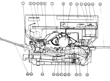
FIGURE 1-2: CROSS SECTION OF 1HE PRINTER (FROl\TT VIEW)
1. Left cover 14. Right panel 2. Fan 15. Manual feed tray
3. DC controller PCB 16. Lower manual pickup roller 4. Display panel 17. Registration shutter
5. Top cover 18. Feeder roller
6. Ozone filter 19. Transfer guide assembly 7. Preconditioning exposure lamps 20. Transfer corona assembly 8. Beam-to-drum mirror 21. Separation belt
9. Photosensitive drum 22. Separation feeder unit 10. Laser\,,lriter I/O board 23. Paper detection arm 11. Scanner mirror 24. Fuser roller cleaner felt 12. Scanner motor 25. Delivery roller
13. Upper manual pickup roller 26. Print tray
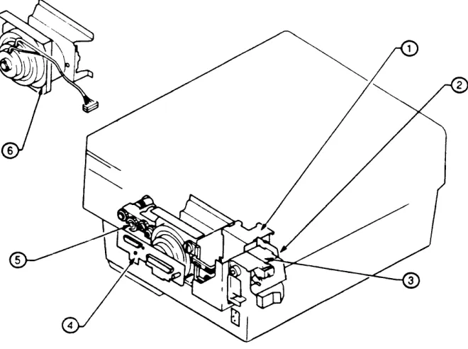
[image:18.612.85.506.112.424.2]FIGURE 1-3: LOCATIONS OF MAJOR ASSEMBLIES
1. DC power supply Imotor drive PCB 2. Scanner unit
3. Laser unit 4. Pedestal
5. Registration shutter assembly
6. Transfer guide assembly 7 Transfer corona assembly
8. Feeder guide assembly 9. Separation/feeder unit
10. Preconditioning exposure and print counter assembly
11. Paper cassette 12. Fuser assembly 13. DC controller PCB 14. Varistor PCB
(
)
)
FIGURE 1-4
1. High voltage power supply 2. Power interlock assembly 3. AC driver PCB
)
LaserWriter rev. Dec 86
4. Mounting connector plate (I/O connector plate)
5. Manual feed assembly
6. Main motor assembly
[image:20.612.160.490.164.410.2]Specifications
LaserWriter liD
Board
Electrical Requirements
Environmental Requirements
Built-in Fonts
Speed
Recommended Weights of Paper
The following specifications apply to both the LaserWriter and LaserWriter Plus printers (unless otherwise noted).
12 MHz 68000 microprocessor, 1.5 megabytes RAM, 512K (LaserWriter) or 1 megabyte (LaserWriter Plus) ROM, AppleTalk and RS-232-C interfaces.
Line voltage: 115 Volts +/- 10% (N orth American model) Line frequency: 60 Hz + / - 2 Hz.
(N orth American model) Power consumption:
Operating: 690 Watts (maximum) Standby: 120 Watts (typical)
Temperature: 50° F to 90.50
F.
Humidity: 20% to 80% relative humidity for optimum performance.
LaserWriter:
Times®, Helvetica®, Courier, and Symbol
LaserWriter Plus:
Times, Helvetica, Courier, Symbol, Palatino®, ITC Avant Garde®, ITC Bookman®, Helvetica Narrow, ITC Zapf Chancery@, ITC Zapf Dingbats®, and New Century Schoolbook
Eight pages per minute maximum throughput. Actual performance depends on the specific application.
Cassette feed: 16-21 lb.
Manual feed: Single-sided printing: 11-33 lb. Double-sided printing: 16-33 lb.
(
)
)
)
Cassette-Feed Information
Manual-Feed Information
Double-sided Printing
LaserWriter
1. Maximum paper load: 0.4 inches (approximately 100 sheets)
2. Load paper with curl-side up, as in an office
photocopier. Before loading paper, fan through the stack to ensure proper feeding.
3. Store paper in its package in a dry location. Do not open a package of paper until you are ready to use it.
1. It is possible to use paper sizes from 4" x 5.5" to 8 1/2" x 14" in manual feed operation.
2. Do not pull the paper from the manual feed guide when the printer begins feeding paper. Pulling the paper out does not abort printing, and it can damage the printer.
Double-sided printing is possible if manual feed is used for the second side. (Attempting to print on the second side of a printed page using cassette feed is likely to cause paper jams.) Insert paper lengthwise along the guide on the manual feed tray, with the side to be printed facing up.
o
THEORY OF OPERATIONS
The LaserWriter printer uses laser light, a sophisticated optical system, and a plastic powder called toner to
produce its images. Using a dot matrix of 300 dots per inch (6.8 million per page), it can produce a variety of high-quality print fonts and graphics, either separately or on the same page. Computers can be connected to the printer either through the AppleTalk network or through the RS232/422 port.
The LaserWriter I/O board (see figures on preceding
pages to identify parts) controls communications between the printer and external computers. It
contains 1.5 megabytes of RAM and either 512 kilobytes (LaserWriter) or 1 megabyte (LaserWriter Plus) of ROM, plus a 68000 microprocessor. During printing, when a document is sent to the printer from an attached computer, the I/O board receives a description of each page in a language called PostScript ™ . (ASCII files can also be accepted, but this discussion will be confined to normal printing from a Macintosh.) It then converts the PostScript commands into a bit image which it stores in RAM and then sends to the printer's DC Controller board. The DC Controller board controls the operation
of the print mechanism and the laser/scanner unit to
produce the actual printed page.
The semiconductor laser produces a beam of infrared light which is directed toward a rotating hexagonal mirror in the scanner unit. The scanner mirror reflects
the beam across a revolving light-sensitive drum in the toner cartridge. As the drum rotates, the result is a
raster scan, very much like the one that forms the picture in a television set.
The drum is given a positive charge by the primary corona wire inside the toner cartridge. Wherever the
light beam hits the drum, it neutralizes this positive charge on a tiny "dot" on the drum's surface. The pattern of dots produced by the laser's beam forms the image.
After being exposed to the laser scan, the drum rolls through the toner powder, which is contained in the same unit (the toner cartridge). The toner is positively charged, so it avoids the positive ("white") areas of the drum surface, but is attracted to the neutral (slightly negative) dots where the laser beam has struck the drum.
(
)
Status Ughts
)
)
LaserWriter
The drum, with its load of toner, then comes in contact with the paper. At this point, the paper is given a strong positive charge by the transfer corona wire.
This positive charge causes the toner to stick to the paper. As the paper travels forward, it is stripped off the drum by the separation belt. It then passes between two heated rollers in the fuser assembly, and the
combination of heat and pressure fuses the toner onto the paper permanently.
The printer has four status lights, three on the display panel at the front of the machine and one on the rear
(I/O) connector plate.
1. The TEST light on the rear (I/O) connector plate (Figure 1-5) comes on continuously (either steady or blinking) if the LaserWriter I/O board is malfunctioning. (If the board is functioning correctly, this light will blink once and then go out when the printer is turned on.)
Test
0
@FIGURE 1-5: REAR (I/O) CONNECTOR PLATE
2. Display panel LEDs (Figure 1-6):
@/////ff/2 t:1??2'lWA wdd/ff/d
U
~
&IV
[image:25.612.295.471.483.654.2]Ready/wait Paper out Paper jam
FIGURE 1-6: DISPLAY PANEL LEDs
a) The green READY light blinks while the printer is warming up and then stays on continuously when the printer is ready to operate.
b) The yellow PAPER OUT light stays on continuously when there is no paper in the paper cassette, or when the paper cassette is not installed. This light blinks when the printer is preparing to print a page. (With manual feed, this yellow LED lights steadily if there is no paper on the manual feed tray.)
c) The red PAPER JAM light stays on continuously when a paper jam occurs. Printing is not
possible until the jammed paper is removed.
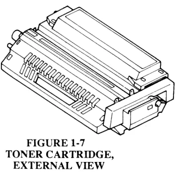
FIGURE 1-7 TONER CARTRIDGE,
EXTERNAL VIEW
(
)
)
)
Toner Cartridge Protective Shield Light-blocking Shutters LaserWriterThe toner cartridge (see Figure 1-7) is a self-contained unit that includes the photosensitive drum, the primary corona wire (which charges the drum), a developing unit, toner hopper, and drum cleaner (see Figure 1-8). The cartridge cannot be disassembled.
[image:26.615.194.539.150.373.2]Light-blocking shutter 1 Light-blocki ng shutter 2 Photosensi tive drum Developing blade
FIGURE 1-8: TONER CARTRIDGE (CROSS SECTION)
The printing life of a cartridge is approximately 3,000 pages, but may vary according to the type of printing done: for instance, graphics that include large black or . shaded areas will use more toner than ordinary text.
The toner cartridge has a protective shield over the area where the paper comes into contact with the drum. When the cartridge is removed from the printer, this shield shuts automatically, preventing light from entering. (If the drum is exposed to light, blank areas and faint black stripes may appear on prints.)
The shield is opened automatically when the toner cartridge is inserted into the printer and the printer is closed. Do not open the shield manually unless
necessary, and do so only in dim light.
The two light blocking shutters protect the areas where the preconditioning lamps "erase" the drum surface and where the laser beam "paints" the image on the drum. These shutters open automatically when the cartridge is inserted into the printer. If the shutters do not close by themselves when you remove a cartridge from the printer, close them manually.
Storage
Handling Suggestions
1. The toner cartridge should be stored at a temperature between 32 and 95 degrees F in a relative humidity of 35% to 85%. Higher or lower temperatures or humidities may reduce the storage life of the cartridge, as will storage in air pressure lower than 0.6 atmospheres or higher than 1
atmosphere.
Note: The expiration date of the cartridge is specified on the cartridge box. The usable lifetime of a toner cartridge is 2 1/2 years from the date of manufacture. Cartridges more than 2 1/2 years old may give poor print quality.
2. Do not place cartridges in direct sunlight or near a window. Do not leave them inside an automobile for a long period in warm weather, even if the cartridges are still in their storage boxes.
3. Avoid storing cartridges in places where the temperature or humidity may change suddenly (for example, near an air conditioner or heater).
4. Avoid storing cartridges in dusty locations and places where they might be exposed to ammonia fumes or organic solvents. (Inform your cleaning staff not to use ammonia near the printer or near stored cartridges.)
5. If a cartridge has been stored at a low temperature, let it come up to room temperature before installing it in a printer. Otherwise, condensation can cause print quality problems.
1. When installing a cartridge, hold it horizontally and rock it slowly back and forth 45°, to distribute the toner. (Figure 1-9.)
2. If white areas occur on prints due to lack of toner, rock the cartridge back and forth to redistribute the toner. This can sometimes coax extra life out of a cartridge that is almost empty.
CAUTION: To avoid toner spillage after
a
toner cartridge's seal is broken, hold it by the handle and rear only, as shown in Figure 1-9.(
)
)
)
LaserWriter
FIGURE 1-9
3. Never touch the surface of the photosensitive drum. If the surface of the drum becomes dirty, open the protective shield and wipe it clean with a piece of flannel that has been liberally sprinkled with toner. Never wipe it with a dry cloth or paper towel, and never use solvent.
4. If the cartridge is left in strong light for a long time, white blanks or white stripes will appear on prints (even if the protective shield and shutters are closed). If this happens, stop the printer and wait a few minutes: the cartridge should be able to "recover" within this time.
Note: Normal room light, measured a few meters from a window on an average day, is about 1,500 lux. Do not expose the photosensitive drum to light of this intensity for more than 5 minutes. If the drum is placed under these conditions accidentally, the cartridge can be stored in a dark place to "recuperate," although an image may be retained on the drum for some time. Direct sunlight is 10,000 to 30,000 lux. A drum exposed to direct sunlight may be ruined.
(
LaserWriter
(
(J
-II
-III=
=
[image:29.612.160.487.144.581.2][)383 •
®
)
)
)
o
PERFORMANCE EVALUATION
Service Test Print
User
Test Print
LaserWriter
The LaserWriter has two test prints. The LaserWriter generates the user test print each time the printer is switched on. The service test print can be generated by the technician during maintenance or repair procedures.
The service test print is produced by jumpering two pins on the DC Controller board. This print exercises the LaserWriter's printing functions but does not involve the LaserWriter I/O board. The print is useful in service situations where a test print is required but the I/O board has been removed. Instructions for generating this print are given in the Troubleshooting section of this manual. The print consists of vertical black stripes on a white
background and covers the entire printing area of the page. (For further information, refer to "Image Skew Adjustments" in Section 3, Adjustments.)
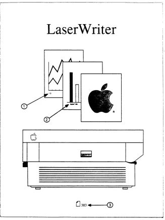
The user test print, reproduced in Figure 1-10, is produced each time the printer is switched on (unless the protocol switch is set to "SpeCial" or the function has been turned off with PostScript software). This test print exercises the LaserWriter I/O board and contains several types of information about the printer configuration. The numbered items below refer
to the numbered arrows in Figure 1-10.
1. The number printed here indicates the revision level of the printer ROM.
2. This square indicates the setting of the mode selector switch at the rear of the printer. If the selection is not "AppleTalk," the baud rate appears at the top of the bar graph, and the I/O port being used (9-pin or 25-pin) is specified at the bottom of the graph.
3. This number represents the number of pages printed so far on this printer.
Aside from these items, the user test print can also tell you:
4. Whether the printer is functioning: If the user test print is produced without problems, the printer is working correctly.
5. Whether the image is properly aligned to the paper: by measuring from the square border to the edge of the paper, you can tell whether the image is tilted further than is acceptable according to Apple's specifications. (See "Image Skew Adjustment" in Section 3, Adjustments.)
)
)
)
o
SETUP AND OPERATION
LaserWriter
Setup and operation instructions for the LaserWriter and LaserWriter Plus are given in the LaserWriter and LaserWriter plus user's manual. The manual covers the following topics:
1. LaserWriter components.
2. Setting up the LaserWriter: includes installing the toner cartridge and its cleaning pad, the paper trays, and the paper cassette.
3. Connecting the printer to the AppleTalkTM network.
4. Using the LaserWriter to print: includes installing LaserWriter software on an application disk, fixing a "disk full" condition, and printing a document.
5. Maintenance and troubleshooting procedures.
6. Print Quality Guide: a preventive maintenance and troubleshooting guide for users.
o
ELECTROSTATIC DISCHARGE (ESD) PRECAUTIONS
Grounds
Bodies
Bags
Leads
Electrostatic Discharge (ESD) can cause severe damage to sensitive microcircuits. Just touching a chip or brushing it with a nylon sleeve can degrade a circuit so that it never again performs to specification. Some microcircuits are sensitive to as little as 500 volts, or about one-sixth as much static electricity as you can feel.
Certain preventive measures must be taken to avoid ESD damage. When you are unwrapping, installing, or replacing any microcircuits, observe the following precautions:
Before working on any device containing a printed circuit, ground yourself and your equipment to an earth or building ground
Use a grounded conductive workbench mat and a
grounding wriststrap, and ground your equipment to the mat.
Don't touch anybody who is working on integrated circuits.
If that person is properly grounded, your "zap" may not cause any damage, but just to be on the safe side, keep your own body charge away from other technicians.
Use antistatic bags for boards and chips during handling.
Whenever you are about to leave your bench and take a board to a storage place, first put the board in an anti-static bag. Leave all Apple service exchange
components in their ESD-safe packaging until needed for use.
Handle all ICs by the body, not the leads.
Also, do not touch PCB edge connectors, exposed circuitry, or printed circuits. Handle ICs and PCBs by the edges, or use extractors.
(
)
SyntheticsMetals
Atmosphere
)
)
Lase rWrite r
Do not wear polyester clothing or bring plastic, vinyl, or styrofoam into the work environment.
The electrostatic field around these nonconductors cannot be removed.
Never place components on any metal surface.
Use antistatic or conductive mats or foam.
If possible, keep the humidity in the service area between 700/0 and 900/0, and use an ion generator.
Charge levels are reduced (but not eliminated) in high-humidity environments and in areas where an ion generator is used routinely.
(
)
(
~)
o
CONTENTS
)
)
LaserWriter
• Apple Technical Procedures
LaserWriter
Section 2 - Take-Apart
(Items marked • are included in the videotapes that accompany this manual.)
2.3 General Information
2.3 Main Screw Types Used 2.5 Safety Precautions
2.6 Electrostatic Discharge (ESD) Precautions 2.7 Other Precautions
·2.8 Covers and Panels ·2.10 LaserWriter I/O Board ·2.12 DC Controller PCB
2.14 DC Power Supply/~otor Drive PCB 2.16 Laser/Scanner Unit
2.17 2.17 2.18 2.20 2.22 2.25 2.26 2.27 2.28 2.30 2.31 2.32 ·2.34 2.37 2.38 2.46 2.49 2.50 2.52 2.54 2.55 2.56 2.66
Separate Laser from Scanner Reinstall Laser on Scanner Laser Beam Blocking Shutter Registration Shutter Assembly Preconditioning Exposure Assembly Fan
Paper Detect Optical Sensor Ozone Filter
High Voltage Power Supply Drive Gear Grounding Spring Main Motor
Power Interlock Assembly Fuser Assembly
Heater Bulb-Fuser Roller Heater Fuser Rollers
Thermistor and Thermoprotector Transfer Corona Assembly Restring Corona Wire Transfer Guides Feeder Guide
Separation/Feeder Unit Printer Pedestal
LaserWriter I/O Power Supply (Interface Regulator)
2.66 Cassette Pickup Assembly 2.67 Lower Paper Feed Guide 2.68 Pickup Rollers
2.71 Pickup Control Clutch 2.72 Paper-out Sensor (PS2) 2.73 Upper Main Body
2.83 Manual Feed Roller Assembly
Note: If a step is underlined, detailed instructions for that step can be found elsewhere in this section.
(
)
)
o
GENERAL INFORMATION
Materials Required
Main Screw Types Used
LaserWriter
Phillips screwdrivers, magnetized:
#2 head, stubby (1.25-inch shaft, 3-inch maximum total length)
#2 head, medium (4-inch shaft) #2 head, long (6- or 8-inch shaft) Long nose pliers (preferably curved) diagonal cutting pliers
Medium flathead screwdriver (or other tool for prying) snap-ring pliers, external, 19-30 mm
safety goggles cable ties
Electrostatic discharge equipment (3M Velostat 8012 Field Service Kit or equivalent)
Allen wrench (2 mm) spring hook (optional)
Screws of types A, B, C, and D (Figure 2-1) occur both as "black" (anodized) and "silver" (conductive) screws in the chassis. To "preserve proper grounding and continuity, replace silver screws only with other silver screws, and black screws with black screws. Whenever you remove screws from the printer, mark on the chassis which type of screw you have removed, so that you can replace it with the same type.
A
Long
B
Long with Flange
rev. Dec 86
c D
siT
t
T
Short Short
with Flange
FIGURE 2·1
E
Long with Un threaded Top
DANGER -NVISIBlE LASER RADIATION WHEN OPEN. AVOID DIRECT EXPOSURE TO BEAM.
ATrENTION -RAYONt.Et.t:NT LASER INVISIBlE SIOlNERT.
AOANGER
DANGEREUX DE REGAADER A l'NT!REuR
VORSICHT -~SICHTBARE LASE RSTRAHLEN WENN GEOFFNET.
Laser assembly contains NO adjustable or serviceable components.
NIGHT HH NSEHEN.
Opening may cause damage to this product or bodily injury including blindness!
Safety Labels: (Scanner unit) Warn against direct exposure to laser. beam.
CERTIFlED ONL Y TO CE CODE
ill CERTIFIE EN VERTU
~
LRG43Q Apple Computer. Inc.Cupertino. California 95014 Made in Japan
OU CCE SEI.A..BENT
Listed E.D.P. Equip. 660F
E73004
Apple L . . er Printer Model Number: M0156
Serial Number:
A
Apple .,., the Apple logo are regoat.,., trlldemarl<a 01 Apple ComplAer. Inc:. 115 V
60 Hz 6.6A
RS1-8085'W
Product Label: (Outside of printer) Includes voltage information.
Apple Computer. Inc.
Cupertino. California 95014 Made in Japan
Manufactured:
Model Number: M0156
This produd conforms with NCDRH radiation performanoa standard. 21 CFR
Chapter 1 Subc:hapter J.
,CAUnON I
To prevent electrical shock. do not re-move ccvw. No user serviceable parts
inside. Refer servicing to qualified
aervi<:e personnel.
RS1-8086
Safety Label: (Bottom of printer) Cautions against opening by anyone other than qualified service personnel.
82S-1125-A
(
)
)
)
o
SAFETY PRECAUTIONS
LaserWriter
1. Always unplug the printer before taking it apart, unless you are testing the electronic assemblies.
2. Never disconnect the optical fiber (see Appendix, Photo 1, #4) from the DC Controller board when the printer is running. The fiber carries infra-red laser radiation, which you cannot see but which can permanently damage your eyes or your neighbor's eyes. Even if you don't look directly at the fiber, the light can enter your eyes by bouncing off reflective surfaces.
3. For the same reasons, never open the laser access hatch (see Photo 1, #9) or the scanner unit (see Photo 1, #3) when the printer is running. (Never open the scanner unit under any circumstances: it contains optical assemblies that must be protected from dust.)
4. The LaserWriter weighs over sixty pounds: Be careful in lifting it!
5. When the printer is running with its covers or panels removed, be careful where you put your hands. There are dangerous voltages on the DC Power Supply (see Photo 1, #7) and the High Voltage Power Supply (see Photo 1, #6).
6. Warning labels appear in locations on the printer wherever special service attention is needed (see illustrations at left). Obey the instructions on the labels.
o
ELECTROSTATIC DISCHARGE (ESD) PRECAUTIONS
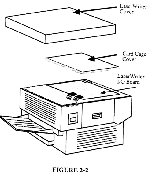
The LaserWriter I/O board (Figure 2-2) is the most expensive single module in the printer, and its components are soldered into place. It is therefore very important to protect the chips on the board from damage. Electrostatic discharge can be an important factor in causing board failures: even if the failures are not immediate and dramatic, static zaps can degrade chips in such a way that they fail weeks or months after exposure.
[image:43.612.245.487.344.625.2]Be sure to follow the ESD prevention information located in Section 1, Basics to avoid damage to any LaserWriter electronics.
FIGURE 2-2
(
)
)
)
o
OTHER PRECAUTIONS
LaserWriter
1. Always remove the LaserWriter toner cartridge before removing anything else from the printer, to prevent damage to the cartridge. When you remove it, be sure the light-blocking shutters are closed, and cover the cartridge so that light will not damage it.
2. Use recommended weights and grades of paper for all tests. For best results, use 16-21 lb. paper, such as the standard paper used in office photocopiers. (See section
I.e
for further paper specifications.)3. Do not pull the paper from the manual feed guide when the printer begins feeding paper. Pulling the paper out does not abort printing, and it can damage the printer.
4. Never open the scanner unit under any
circumstances: it contains optical assemblies that must be protected from dust. Apple will not accept a scanner unit for exchange if it has been opened.
o
COVERS AND PANELS
Top Cover
Front Panel
To remove the Top Cover (Figure 2-3)
1. Open the printer (raise the upper main body by pressing up on the release lever).
2. Open the cartridge access door and remove the toner cartridge. Leave the cartridge access door open.
3. Remove the two top-cover screws inside the cartridge door.
4. Remove the two screws on the other side of the top cover.
5. Lift off the top cover.
To remove the Front Panel (Figure 2-3)
1. Remove the top cover.
2. Remove the four front panel screws.
3. Lift off the panel, carefully disengaging it from the case-opening lever.
Top Cover
Left---t-t
Panel
Print-t~~~
Tray Cover
Release'---~
Lever
FIGURE 2-3: FRONT VIEW
Front Panel
Toner Cartridge Access Door
(
)
)
Right Panel
Rear Panel
Left Panel
Replace Panels and Cover
LaserWriter
To remove the right panel (Figure 2-4):
1. Remove the front panel.
2. Close the printer.
3. Remove the two right panel screws and lift off the panel.
To remove the rear panel (Figure 2-4):
1. Remove the front panel and right panel
2. Remove the two rear panel screws and lift off the panel.
To remove the left panel (see Figure 2-3):
1. Remove the front panel right panel and rear panel.
2. Remove the four left panel screws and lift off the panel.
To replace the panels and cover:
1. Fit the left panel on the chassis and install the four screws.
2. Do likewise for the rear panel, right panel, front panel, and top cover.
Right Panel
Note: The Apple logo on the top cover faces the front of the printer.
~;-t---Rear Panel
FIGURE 2·4: REAR VIEW
o
LASERWRITER
1/0
BOARD
Remove
The LaserWriter I/O board (Figure 2-5) contains a 68000 microprocessor, 1.5 megabytes of RA1vl, and SOOK bytes of ROM. It controls communications between the printer and outside devices (computers and file servers) and contains the electronics that construct the printer's fonts.
LaserWriter Cover
LaserWriter I/O Board
FIGURE 2-5
Note: Before replacing a customer's I/O board, run a test print. Then compare the print count on the test print to the count shown on the print counter fuse on the preconditioning exposure assembly. (You do not have to remove the assembly to view the counter; you can see it if you remove the DC controller board, as directed in this Take-Apart section.) If the numbers match, note the count in the printer's record. If the numbers do not match, record the count shown on the fuse.
1. Remove the top cover.
2. Remove the screws that hold the top of the card cage in place.
3. Lift off the card cage cover.
(
)
)
)
Replace
Remove to Gain Access
LaserWriter
CAUTION: Before touching any board, make sure you are properly grounded. Static electricity can destroy
expensive boards in an instant.
4. Disconnect the three cables. Pull on the connectors only, not on the cables.
If you are replacing the I/o board, go to "Replace." If you are removing the I/O board to gain access to other parts of the printer, skip to "Remove to Gain Access."
To replace the I/O board:
Note: The I/O board is held down by plastic standoffs. On later versions of the LaserWriter, some plastic standoffs may be replaced by metal fasteners. Remove any metal fasteners before trying to lift the board.
1. Pinch the plastic standoffs to disengage the board.
2. Lift the board out, holding it by the edges only, and place it in a static-protective bag or on a workpad grounded to the LaserWriter. Always make sure you are grounded to the LaserWriter before touching this board.
3. Put the new I/O board into place, push it down so that the standoffs engfige, refasten any metal fasteners, and reconnect the three cables.
Note: Inform the customer that replacing the I/O board causes the test print count to be inaccurate. You can run a test print from the replacement I/O board and suggest that the customer record the difference between this test print count and the figure you earlier recorded in the printer's record.
To remove the I/O board assembly to gain access to other parts of the printer:
1. Remove the screws that hold the card cage to the chassis.
2. Lift the board and card cage out carefully.
o
DC CONTROLLER PCB
Remove
The DC controller board (Figure 2-6) controls most of the print functions in the LaserWriter.
Optical Fiber
DC Controller PCB
Scanner Unit
Cover Interlock Assembl
DC Power Supply/ Motor Drive PCB
FIGURE 2-6: TOP VIEW WITH
LASERWRITER I/O BOARD REMOVED
Varistor PCB
1. Remove top cover and Lase!"\X1riter I/O board.
CAUTION: In the next step, do not bend the optical fiber that comes from the laser. The fiber is part of the left-margin-detect circuitry. If bent, the fiber can break, and the printer will not be able to detect when the laser has reached the left margin of the page.
2. Disconnect all the connectors on the DC controller
PCB.
3. Release the board from its five nylon standoffs and remove it.
(
)
Replace)
)
LaserWriter
IMPORTANT: Replace the DC Controller board only with
another Apple DC Controller board.
1. Place the board on its five nylon connectors and push it down until they hold it in place.
2. Connect all cables to the board. The connectors are of different sizes: if you match them to their sockets exactly, you will have no problem. (The sockets labelled J213 and J205 are not used at this time.)
3. Reconnect the laser optical fiber and the eight-wire laser cable to the DC Controller board.
4. Replace the LaserWriter I/O Board and the 1Ql2
cover.
Note: When you install a new DC Controller Board in a printer, you must adjust the laser power. See the Laser Power Adjustment in Section 3.
o
DC POWER SUPPL Y/MOTOR DRIVE PCB
Remove
The DC Power Supply/Motor Drive PCB (see Appendix, Photo 1, #7) has two major components. The Motor Drive circuit turns the main motor on and off according to a command from IC 208 on the DC Controller board. The DC Power Supply generates and outputs DC voltages and sequence control signals.
1. Remove the top cover the right and rear panel and the LaserWriter I/O Board
2. Disconnect the three connectors from the DC Power Supply/Motor Drive PCB.
Note: If necessary, use a flatblade screwdriver to help pry off the connectors, but do not pull on the wires.
5. Remove the five mounting screws on the metallic part of the assembly (see Figure 2-7; do not remove
the five screws on the PCB). Lift the unit off the
)
)
Replace
)
[image:52.613.229.567.56.442.2]LaserWriter
FIGURE 2·7: DC POWER SUPPL Y MOTOR DRIVE PCE
IMPORTANT: In step 1, take care not to pinch the motor cab/e.
1. Put the unit in position and replace the five long black mounting screws.
2. Connect the three cables to the unit. Make sure to connect the large cable to the DC Controller board.
3. Replace the LaserWriter I/O board, the panels and cover.
rev. Dec 86 Take-Apart /2.15
R
E A R
o
F
P R
I N T E
o
LASER/SCANNER UNIT
Remove
The laser unit (see Appendix, Photo 1, #1) produces the infrared laser beam. The scanner unit (Photo 1,. #3) contains a rotating hexagonal mirror that directs the beam along the length of the photosensitive drum in the toner cartridge.
1. Remove the top cover and the LaserWriter I/O lma.r.Q.
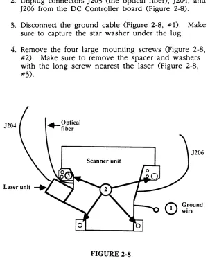
2. Unplug connectors )203 (the optical fiber), )204, and )206 from the DC Controller board (Figure 2-8).
3. Disconnect the ground cable (Figure 2-8, #1). Make sure to capture the star washer under the lug.
4. Remove the four large mounting screws (Figure 2-8, #2). Make sure to remove the spacer and washers with the long screw nearest the laser (Figure 2-8, #3).
J20~ ...-Optical
fiber
[image:53.612.221.524.259.649.2]J206 Scanner unit
FIGURE 2-8
(
)
)
)
Replace
Separate Laser from Scanner
Reinstall Laser on Scanner
LaserWriter
5. Very carefully lift the laser and scanner unit straight up and out of the printer. Rest it upside down on a stable, static-free surface.
IMPORTANT: When you receive a new laser/scanner unit from Apple, it will be shipped with a laser shorting
connector on the end of the laser cable. Install this connector on the old laser unit before shipping it back to Apple for repair. Be sure pin 4 is shorted to pin 6. Shorting these two pins prevents static electricity from damaging the laser unit.
1. Put the laser/scanner unit back into place. Make sure no cables are trapped beneath the unit.
2. Connect the ground cable to the hole nearest the right panel.
3. Replace the four large mounting screws. NOTE: The long screw goes through the spacer and washers
in the hole nearest the laser unit (Figure 2-8, #3).
4. Reconnect the cables to DC Controller Board jacks )203, )204, and )206.
5. If this is a replacement unit, perform the Laser Power Adjustment (see Section 3, Adjustments).
1. Remove the Laser/Scanner Unit.
2. Pull back the rubber cap on the laser unit and remove the two 2mm Allen screws.
3. Pull the laser unit free.
1. Put the laser unit into position on the scanner unit; make sure the cable marked TB3 comes out 'on the same side as the optical fiber.
2. Put the two Allen screws in loosely, and then tighten them alternately so that the unit fits firmly into place.
3. Replace the Laser/Scanner Unit.
o
LASER BEAM BLOCKING SHUTTER
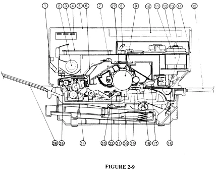
This shutter (Figure 2-9, #27) is located beneath the laser and scanner units. It is opened mechanically when the toner cartridge is inserted into the printer, and should not need repair. To check it for cleaning and/or lubrication, remove the laser/scanner unit, locate the shutter and make sure that it moves freely.
~
\\
[image:55.612.108.538.244.619.2]\
FIGURE 2·9
~
\\
(
(
)
Remove 1. Remove the Laser /Scanner Unit.2. Remove the two screws that hold the ozone seal plate in place.
3. Unhook the two tension springs from the Laser Beam Blocking Shutter.
4. Remove the two screws holding the shutter in place.
5. Lift the edge of the shutter closest to the DC Controller PCB and simultaneously remove the shutter from the unit.
Replace 1. Put the shutter in place.
2. Replace the two screws and plastic bushings.
3. Re-hook the two tension springs on the shutter. 4. Put the ozone seal in place and replace the two
mounting screws.
)
)
Detail A
o
REGISTRATION SHUTTER ASSEMBL V
The registration shutter assembly is located in the upper "jaw" of the printer, near the hinges. When paper is fed into the paper path, either from the cassette or from the manual feed tray, the registration shutter stops the paper until all systems are
synchronized and the edge of the paper is straight. Then the printer energizes the registration solenoid, which lifts the shutter and allows the paper to pass on to the toner cartridge.
FIGURE 2·10: RIGHT SIDE OF PRINTER
WITH PANEL REMOVED
(
)
Remove
)
Replace
)
LaserWriter
IMPORTANT: Before starting, locate the cartridge-detect micros witch assembly and note how the white plastic arm is seated between two metal tabs (Figure 2-10, Df?tail A). This is your test for whether the assembly has been replaced correctly. If the white plastic arm is not properly seated, the printer will not function: it will "think" that the toner cartridge is not installed and the green READY light on the front panel will not come on.
1. Remove the Laser/Scanner Unit
2. Remove the DC Power Supply/Motor Drive PCB Assembly
3. Using long-nose pliers, remove the three-wire connector (see Figure 2-10, #1) and the four fast-on connectors (see Figure 2-10, #2).
4. Remove the two silver screws visible from the top through the two access slots (one on either side of the assembly).
5. Open the printer. The registration shutter assembly should be resting on the lower body of the printer.
6.
Remove the green ground wire from the front side of the registration shutter, and lift the assembly out of the printer.1. Put the shutter assembly in place on the lower body of the printer, and reconnect the ground wire.
2. Lift the shutter assembly into its place in the top of the printer. Check the white plastic arm of the microswitch unit to make sure it is correctly seated. (Figure 2-10, detail A.)
3. Holding the assembly in place with one hand, replace the two short flanged silver screws.
CAUT10N: You should not have to force the assembly into position. If the screw holes are not aligned correctly, reposition the whole unit.
4. Test for correct installation by closing and opening the printer. There should be no binding.
5. Replace the cable connector and the fast-on connectors.
6. Replace the DC Power/Motor Drive PCB.
7. Replace the Laser/Scanner Unit and all panels and covers
o
PRECONDITIONING EXPOSURE ASSEMBLY
The preconditioning exposure assembly (Figure 2-11,
#1) prepares the print drum in the toner cartridge for a new image. The lamps expose the print drum to a uniform light that neutralizes any leftover charges from the last print cycle, thus "erasing" the previous image from the drum.
The print counter (Figure 2-11, #2, a fuse-like component that is part of the assembly) shows how many prints have been made on the printer since the counter was installed. Each numbered mark on the counter represents approximately 10,000 pages. When the mercury bubble in the counter reaches "10," the counter should be replaced.
It is not necessary to remove the assembly to view the counter; you can see it if you remove the ozone filter (see instructions for removing the ozone filter).
In these instructions, right and left are used with reference to Figure 2-11.
(
)
)
Remove
Replace
)
LaserWriter
FIGURE 2·11
1. Remove the DC Controller PCB.
2. Remove the single mounting screw at the left of the assembly (see Figure 2-11, #3).
3. To remove the assembly, put one finger on the right side of the assembly and push to the left until the tab at the right (see Figure 2-11, #4) comes free.
4. Lift the assembly out of the printer.
When replacing this assembly, transfer the old print counter (which looks like a fuse) from the old assembly to the new, unless the old print counter reads "10." If the print counter reads "10," replace it.
1. Put the assembly in place. To seat it, gently push down on the tab at the right (using a pencil or similar pointed tool) while pushing the assembly to the right.
2. When the assembly is properly seated, replace the mounting screw.
3. Replace the DC Controller PCB
(
(
)
o
FAN
Remove
)
Replace
)
LaserWriter
The fan is located along the left side of the upper main body (see Figure 2-12).
1. Remove the tOD cover front Danel. right Danel rear Danel and left Danel.
2. Remove the LaserWriter I/O board and the
ll1:
Controller PCB.
3. Remove the left side-frame (see Figure 2-12, #2) by removing its six silver screws.
4. To remove the fan cover (the metal plate above the fan, see Figure 2-12, #3), remove the three screws and lift the fan cover out of the chassis.
5. Unplug the two-wire white fan cable and free it from its clamp.
6. Remove the two fastening screws and take out the fan.
1. Put the fan into place.
2. Put the fan cable into its clamp and reconnect it to its mate.
3. Install and tighten the two fastening screws.
4. Put the fan cover (see Figure 2-12, #3) into place (try different positions until you are sure it fits correctly: the tab for the side screw (Figure 2-12,
#5) fits outside the chassis frame) and install the three screws.
Note: The screw on the side is easy to drop into the mechanism. To avoid that, start the screw by hand.
5. Replace the side frame and its six short silver screws.
6. Replace the DC Controller board, the LaserWriter 110 board, and all panels and covers.
o
PAPER DETECT OPTICAL SENSOR
Remove
Replace
1. Remove the fan
2. Free the sensor cable from its clamp.
3. Open the printer.
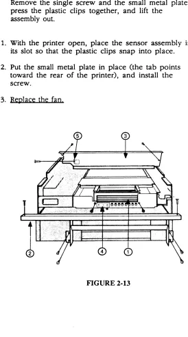
4. The optical sensor assembly is attached to the center of the left side of the printer (Figure 2-13, #4). Remove the single screw and the small metal plate, press the plastic clips together, and lift the
assembly out.
1. With the printer open, place the sensor assembly in its slot so that the plastic clips snap into place.
2. Put the small metal plate in place (the tab points toward the rear of the printer), and install the screw.
[image:63.612.232.506.232.724.2]3. Replace the fan
FIGURE 2-13
(
)
o
OZONE FILTER
Remove
Replace
)
)
LaserWriter
The ozone filter sits below and behind the fan, just forward of the preconditioning exposure lamps and above the toner cartridge.
1. Open the printer and remove the toner cartridge.
2. Locate the ozone filter: it is a gray plastic piece located just above the toner cartridge, between the fan and the red plastic preconditioning exposure window (Figure 2-14). You have to look and reach under the fan to find it.
3. Remove the fastening screw, move the ozone filter slightly up, and pull it out.
Put the ozone filter in place and install the single scre\\!.
Ozone filter
~
FAN
~
I
'.
J
[image:64.612.287.480.371.681.2]\ j
FIGURE 2-14
o
HIGH VOLTAGE POWER SUPPLY
Remove
The high voltage power supply (see Appendix, Photo 1, #6 for location) generates high voltage for the transfer corona wire and also for two elements in the toner cartridge: the primary corona wire and the developing assembly.
1. Remove the top cover front panel right panel left panel. rear panel. and Laser\\friter I/O board.
2. Remove the rear chassis frame as follows:
a) Remove the three connectors from the varistor PCB (Figure 2-15, #1, and Photo 1, #10).
b) Mark the type of screw at each location on the frame with a pencil (for example, "short silver" or "long black"). Then remove screws and lift off the frame piece (Figure 2-15).
3. Open the printer.
4. Remove the black, flanged, fastening screw from the high voltage power supply cover and remove the cover-wiggle it off: it's held on by friction from the wires trapped beneath it.
short silver
short black
FIGURE 2-15
Varistor
PCB
short silver
(
)
)
Replace
)
LaserWriter
5. Disconnect the two connectors with thick red wires (Figure 2-16, #1 and #2) from the high voltage power supply-one connector has t\\'O \\Tires, the other has one. Use a screwdriver to help pry off the connectors.
--~
)
01
FIGURE 2-16: HIGH VOLTAGE POWER SUPPLY
6. Disconnect J211 from the DC controller board.
7. With the printer open, remove the single mounting screw and remove the power supply.
Note: If practicing these procedures, go to Main Motor removal before replacing the high voltage power supply.
1. Attach the power supply to the chassis using a short black screw.
2. Attach the two large connectors to the power
supply, and attach the eight-pin connector to J211 on the DC controller board.
3. Put the power supply's cover into place. The edge of the cover fits into the \vhite plastic guides on the chassis, and the two-wire varistor cable fits beneath the cover. (The single green 'wire should not be beneath the cover.)
4. Replace the cover screw (short, black, 'with flange).
5. Replace the rear chassis frame, using the correct screws as you noted them on the frame.
Note: The white plastic stud on the high voltage power supply fits through a hole on the frame. This stud helps to position the frame.
6. Reconnect the three connectors to the varistor PCB.
7. Replace the Laser\,(lriter I/O board. and the panels and covers.
o
DRIVE GEAR GROUNDING SPRING
Remove
Replace
1. Open the printer.
2. Remove the toner cartridge.
3. Locate the drive gear grounding spring, \vhich is in the center of the largest drive gear. (See
Illustrated Parts List.)
4. Lift out the spring using needlenose pliers or tweezers.
1. Replace the drive gear grounding spring, wide end first, in the center of the largest drive gear. Push on the spring to make sure it is firmly seated.
2. Replace the toner catridge.
3. Close the printer.
(
)
o
MAIN MOTOR
Remove
)
Replace
)
LaserWriter
The main motor (Figure 2-17) turns the paper feed mechanism gears and the toner cartridge drum gear.
FIGURE 2·17
1. Remove the high voltage pov,rer supply.
2. Unplug the motor connector from the DC pO·.':er supply/motor drive PCB.
3. Remove the four large screws that secure the main motor to the chassis.
4. Hold the motor as you remove the one small screw from the metal plate a