Weaving True-Concurrent Aspects using Constraint Solvers
Juliana K. F. Bowles School of Computer Science
University of St Andrews St Andrews KY16 9SX, UK Email: [email protected]
Behzad Bordbar, Mohammed Alwanain School of Computer Science
University of Birmingham Edgbaston, Birmingham B15 2TT, UK Email:{b.bordbar|m.i.alwanain}@cs.bham.ac.uk
Abstract—Large system models usually consist of several sim-pler models that can be understood more easily. Making changes to the behaviour of a component will likely affect several models and could introduce accidental errors. Aspects address this by modelling new functionality required in several places as anadvice, which can be integrated with the original base models by specifying a pointcut. Before checking that the overall outcome is correct, we need to weave the cross-cutting advice into the base models, and obtain new augmented models. Although considerable research has been done to weave models, many such approaches are not fully automated. This paper looks at aspect weaving of scenario-based models, where aspects are given a true-concurrent semantics based on event structures. Our contribution is a novel formal automated technique for weaving aspects using the Z3-SMT solver. We compare the performance of Alloy and Z3 to justify our choice.
1. Introduction
Aspect-oriented programming aims to modularise the development of software by separating crosscutting concerns into different modules. Although aspect-oriented program-ming was originally intended for increasing modularity and separation at the code level, the concepts have been proven very useful for reducing design complexity at the modelling level. Aspect-oriented modelling (AOM) offers mechanisms for separating crosscutting concerns in models through so-called aspects. AOM techniques use the term advice for the action an aspect will take, and pointcut to specify more general rules of where to apply an advice. AOM is particularly useful for dealing with non-functional properties and dependability concerns (including security, reliability, availability, safety, and so on) which usually cut across the system as a whole [1].
To obtain an overall model of the system, we may need to integrate one of more crosscutting concerns (advice models) into the system’s model (base). This process, known as aspect weaving, has received considerable attention in recent years [1], [2], [3], [4]. Providing an overall model is essential, because it contributes to a better understanding of the system behaviour, and makes it possible to analyse
the correctness of the model. Here, we are concerned with a weaving method for UML 2.4 sequence diagrams [5].
Composing sequence diagrams manually for large and complex systems is unrealistic. As a result, various auto-mated methods for model composition have been introduced [1], [2], [3], [4], [6], [7], [8], [9], [10]. Most of these methods introduce algorithms to produce a composite model from simpler models obtained from partial specifications. In recent work [9], [10], we presented a fully automated approach for the composition of sequence diagrams making use of the constraint solver Alloy [11]. Moreover, a well known problem of how poor tool performance impacts on their applicability for large and complex models is discussed for instance in [12], [13]. As a result, this paper investi-gates an alternative composition method in the context of AOM weaving through the use of Z3 [14]. Z3 is a high-performance SMT solver from Microsoft Research, targeted at solving problems arising in software analysis and verifi-cation [14]. Furthermore, we present a novel true-concurrent semantics for sequence diagram weaving, and a model-driven transformation of sequence diagrams to Z3, which preserves the semantics of composition and addresses the scalability of models. We carried out a series of experiments to evaluate and compare the suitability of two solvers (Z3 and Alloy).
The remainder of the paper is structured as follows: Section 2 highlights the key contributions of this paper. Sequence diagrams and their semantics are given in Sec-tion 3. We introduce an example in SecSec-tion 4, and a detailed description of our approach in Section 5. Section 6 shows a comparison study between Z3 and Alloy. Finally, Section 7 discusses related work, and Section 8 concludes the paper.
2. Our Contribution
There are two fundamental problems that need to be considered when composing models, where weaving can be seen as a form of composition: composition must be well defined to be feasible for automation, and the associated algorithm must beefficient.
the logical constraints associated to our source models, which serve as input to the constraint solver. Thereafter, the constraint solver produces (if existing) a solution for the composition in accordance to our formal semantics.
The second problem, namely the efficiency of the com-position algorithm, requires some further analysis by run-ning different experiments and performing a comparison with suitable alternatives. Naturally, the problem arises when the models to be composed increase in size and complexity, but it is also influenced by how the transformation was implemented, the complexity of the composition algorithm and the programming language used.
In recent work [9], [10], we have presented a method for sequence diagram composition based on Alloy. The approach taken does not directly involve an algorithm to compose sequence diagrams, but rather uses Alloy to pro-duce all possible solutions for the composition, where each solution is a possible trace of execution in the composed model. The composed model in Alloy satisfies the conjunc-tion of all logical constraints associated to the sequence diagrams and additional matching constraints. The approach does not, however, explicitly incorporate the semantics of scenarios in the transformation itself. Further, whereas in [9] composition is treated as a simple conjunction of models through syntactic matching of elements of both models, in [10] we allow the matching glue to consist of additional behavioural constraints (for instance imposing an order, disallowing event occurrences, etc). Our approach in this paper is more generic, and covers a more complex form of composition through aspect weaving.
3. Modelling Aspects
UML sequence diagrams capture scenarios of execution as object interactions, and are also commonly used to model aspects and aspect weaving. As such they naturally capture notions such as base model, advice and pointcut [1], [8], [15], [16].
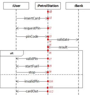
A sequence diagram shows all objects involved in the interaction it describes. Each object has a vertical dashed line calledlifeline showing the existence of the object at a particular time. Points along the lifeline are calledlocations (a terminology borrowed from LSCs [17]) and denote the occurrence of events such as sending/receiving a message. The order of locations along a lifeline is significant denoting, in general, the order in which the corresponding events occur. One example of a sequence diagram showing a base model is given in Figure 1. This example is explained in detail in Section 4. There are three instances involved in the interaction, and we show explicitly the locations along the lifeline of (the arbitrary) instance of class PetrolStation.
Amessageis a synchronous or asynchronous communi-cation between two objects shown as an arrow connecting the respective lifelines, that is, the underlying send and re-ceive events of the message. Asynchronous communication is shown by an open arrowhead and is the form of commu-nication used in this paper. Aninteractionbetween several objects consists of one or more messages, but may be given
l1
l2
l3 l4 l5
l6
l7
l8 l9
l10 l0
[image:2.612.359.512.68.228.2]l11 l12
Figure 1: Petrol station base model
further structure through so-called interaction fragments. There are several kinds of interaction fragments includ-ing seq (sequential behaviour), alt (alternative behaviour),
par(parallel behaviour),neg(forbidden behaviour), assert
(mandatory behaviour), loop (iterative behaviour), and so on [5]. Depending on the operator used, an interaction fragment consists of one or more operands. In the case of the alt fragment, each operand describes a choice of behaviour. Only one of the alternative operands is executed if the guard expression (if present) evaluates to true. If more than one operand has a guard that evaluates to true, one of the operands is selected nondeterministically for execution. In the case of theparfragment, there is a parallel merge between the behaviours of the operands. The event occurrences of the different operands can be interleaved in any way as long as the ordering imposed by each operand as such is preserved.
The model in Figure 1 contains one alternative fragment with two operands. The events associated to the locations of the instancePetrolStationare ordered (one occurs before or after another) unless they are associated to locations within different operands of the alternative fragment in which case they are mutually exclusive.
When modelling with aspects, we start with one or more scenarios capturingbasebehaviour. If we then need to add a new piece of functionality or a concern that may cut across many parts of the system (such as a dependability require-ment) we model the new piece of behaviour as anadvice. In order to integrate the advice into the base behaviour we need to specify how this should be done through apointcut. In order to be able to define and implement a technique for weaving aspects given as scenarios, we have to make sure that we understand the meaning of a scenario (base model or advice) and how to compose them under certain conditions (pointcut). In other words, we need to have a formal semantics for the scenario-based language and a formally defined parallel composition with synchronisation (done in accordance with the pointcut).
an overview. We have given a formal semantics to sequence diagrams in [19] using a true-concurrency model, namely labelled event structures (LES) from [20]. We have defined parallel composition with synchronisation for LES formally in [21]. Our approach in this paper effectively automates a weaving mechanism in accordance to this semantics.
LES are very suitable to describe the traces of execution in sequence diagrams, being able to capture directly the notions available such as sequential, parallel and iterative behaviour (or the unfoldings thereof) as well as nondeter-minism. For each of the notions we use one of the (binary) relations available over events: causality, nondeterministic choice and true concurrency.
We keep the presentation of the semantics as simple as possible here. A LES consists of a set of events and binary relations on events which satisfy certain conditions. The binary relations are causality (a partial order) and nondeterministic choice also called conflict (an irreflexive, symmetric relation which propagates over causality). The formal definition is given below, whereL is an alphabet of labels.
Definition 1.A labelled event structure (LES) is a tupleE= (Ev,→∗,#, µ)whereEv is a set of events with binary relations→∗,# ⊆Ev×Ev for causality andconflict respectively. Causality→∗is a partial order, and conflict
#is irreflexive and symmetric.Conflict propagates over causality, that is, for arbitrary events e1, e2, e3 ∈Ev if
e1#e2 ande2 →∗ e3 then e1#e3. A labelling is given
by µ : Ev → L, a (possibly partial) function which maps events to labels inL.
There is a further implicit relation between events in a LES, namelyconcurrency. Two eventse1, e2are concurrent,
written e1 co e2, iff they are neither related by causality
nor by conflict. Since system computations always have a starting point, we only consider discrete event structures here, that is, structures where the set of previous occur-rences of an event (also calledlocal configuration) is finite. Formally, the local configuration of an event e, given by ↓ e = {e0 | e0 →∗ e}, is finite. This allows us to refer to the notion of immediate causality. Formally, two events e1, e2 ∈Ev, related by causality e1 →∗ e2, are related by immediate causality, written e1 → e2, if we cannot find
another event e3 with e1 6= e3 6= e2, such that e1 →∗ e3
ande3→∗e2. Further, aconfigurationC inE consists of a
subset of events that isconflict free anddownwards closed (i.e., for an arbitrary evente∈C, ife0→∗ethene0
∈C). A traceτ inE is a maximal configuration. A LES encodes all possible traces of execution. A further useful notion is that of a LESmorphism. A LES morphismhis a partial function h: E1 → E2 such that for an arbitrary configuration C in E1,h(C)is a configuration inE2, andhis injective onC.
To give a semantics to sequence diagrams with LES, we need a labelling function that relates events to diagram locations. To keep it simple, one possible label for an event could be (m, s) or (m, r) to denote sending or receiving a messagem respectively. We assume that other events do not have labels. Let M be the set of message labels, and
I be the set of instances associated to a diagram. We can partition the set of events Ev = U
i∈IEvi such that each
subset Evi denotes the events along a lifeline ofi∈I. In
[image:3.612.333.538.137.378.2]other words, each event in a LES associated to a sequence diagram corresponds to a unique instance of the diagram.
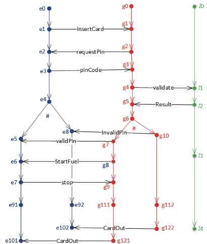
Figure 2: LES associated to the petrol station base model
The LES associated to the example from Figure 1 is illustrated in Figure 2. Minimal events, where a minimal event e satisfisfies ↓ e = {e}, are always associated to a different instance from the sequence diagram. In Figure 2, onlyimmediate causality→is shown. Events belonging to different instances are related by immediate causality iff they are associated to the sending/receiving of the same message (for instance, g10 → e8 on message invalidPin).
Note that in Figure 2 we indicate the name of the message on the immediate causality between send and receive events only for convenience. In effect what we have is for instance µ(g10) = (invalidPin, s) and µ(e8) = (invalidPin, r). The existence of events in conflict in this example reflects the alternative fragment in the sequence diagram which shows two alternative interactions. Conflict is shown, for instance betweeng7#g10denoting the case of a valid and invalid pin
respectively. Conflict propagates and future events are also in conflict, so for instanceg9#g10, and so on. This example
contains two possible traces of execution.
(a) Base (b) Advice (c) Pointcut
Figure 3: Models of the petrol station example
describe anegfragment, we must distinguish allowed from disallowedtraces of execution which we do not do here. We have dealt with this operator in [10], where the composition glue can specify disallowed behaviour overall. The effect is that we prune all possible (composite) traces that contain disallowed behaviour.
4. Example
Consider a simple example of how the behaviour of a system given as a scenario may have to be extended, and how this can be done through the use of aspects. The example describes a petrol station scenario which was adapted from [22]. Let us consider the base model first as shown in Figure 3(a). In this scenario a user of a petrol station can only fill their car with petrol provided they have a card (and know the pin code for the card).
The scenario starts with the user inserting a payment card (insertCard). The petrol station requests the pin code from the user (requestPin), which the user then enters (pinCode). The petrol station sends a message to the bank to validate the pin code (validate and result), and an alt fragment is used to model the two possible outcomes:(1)
the pin code is valid, the user is allowed to start fuelling (startFuel), and when the user has finished he/she stops (stop);(2)the pin code is invalid, the user is informed that the pin code entered is invalid (invalidPin). In both cases, the scenario ends by ejecting the card (cardOut).
Now assume that we want a more refined model where we allow the user to indicate the exact amount of fuel required in advance. This is added by modelling an advice as shown in Figure 3(b).
The advice model starts with a valid pin code scenario. The idea here is that after entering the amount of fuel re-quested the petrol station forwards a message to the bank to validate whether the request is acceptable (basically the user has enough balance to cover the request). Again two options are possible. If the account balance covers this amount, it
will be debited from the account and the petrol station will start fuelling. However, if the account balance cannot cover the amount requested the transaction is cancelled.
To consider the advice within the original base model corresponds to weaving it into the base model and obtain an augmented model. Strictly speaking we can have more than one base model in a system and may want to integrate more than one advice. Without loss of generality we can assume that we can first obtain a composed model for the base behaviour and deal with weaving of an advice one at a time. Note that there may be an interaction (conflict) between two advices and our method would detect that when applying weaving the second time, but we are not explicitly dealing with aspect interaction in this paper. The order in which advices are weaved into a model can produce different results, and the designer needs to take this into account when applying weaving in succession. Our technique can in addition be used to identify these differences automatically. In order to do the weaving, we specify a pointcut which shows how the elements in the base and advice models match. The pointcut in Figure 3(c) indicates that the lifelines and messagesvalidPinandStartFuelare matched.
Bowles [21] showed how to compose two diagram mod-els by injecting new behaviour into a model through a category-theory based construction. Even though weaving was not the intention of that paper, the results make it clear that weaving an advice into a base model in accordance with a pointcut is feasible, and a solution (if it exists) can be obtained (by hand) with this construction. The idea of the categorical construction applied to the present context is as follows. LetEbandEabe the LES associated to the base and
advice models respectively, and letEpbe the LES associated
to the pointcut. If we can define two surjective morphisms fb:Eb→ Ep andfa:Ea → Ep such thatfb(Eb) =fa(Ea),
µb(eb) =µp(fb(eb))andµa(ea) =µp(fa(ea)), then we are
the events identified in accordance to fb and fa, and by
definition is such that configurations are preserved and have injective mappings (for full details cf. [21]).
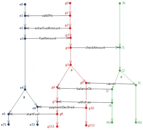
[image:5.612.61.290.162.370.2]For our example, the LES for the base has been given in Figure 2. Consider the LES for the advice as shown in Figure 4. Assume all events are further indexed byb(base) or a(advice) to avoid confusion.
Figure 4: LES for the advice
The LES for the pointcut Ep (not shown) contains
four events {e1p, e2p, e3p, e4p} and the following
causal-ity relations e1p → e2p, e1p → e3p, e2p → e4p and
e3p → e4p. We would have morphisms defined such that
fb(g7b) = e1p = fa(g1a), fb(e5b) = e2p = fa(e1a),
fb(g8b) = e3p = fa(g8a) and fb(e6b) = e4p = fa(e5a).
The categorical construction is thus applicable and we are able to obtain a solution. This paper automates the process using Z3 [14].
5. Automated Weaving
5.1. Overview
Sequence diagrams capturing the base, advice and point-cut models are transformed into equivalent textual repre-sentations of their underlying semantics in LES. The trans-formation is defined at the metamodel level [23], that is, we have a metamodel representation for sequence diagrams and for LES, and translate elements of one metamodel into elements of the other. We treat a pointcut as a simple sequence diagram, which gives us an indication of the matching constraints. We then transform the LES models into equivalent Z3 [14] models. Since LES is a formal model (essentially a set and relations on elements of this set, and additional labels) the transformation to Z3 (where we have first-order logical constraints and functions) is fairly straightforward. A unique Z3 model is produced for each
LES model. The constraint solver considers the conjunction of all logical constraints associated to the three models, and generates a solution which corresponds to the augmented model in accordance to the semantics of parallel composi-tion as defined in [21]. If the matching cannot be done Z3 returns unsat (unsatisfiable) which means that no solution exists. Recall that formally this means that we cannot find surjective LES morphismsfbandfa on which to apply the
categorial construction.
In our approach, all models have to be converted into Z3 specifications, and we focus on the LES to Z3 transforma-tion step. Transformatransforma-tion rules define the mapping between a source (LES) and target (Z3) metamodel. A transformation engine executes the transformation rules on a source model to generate its equivalent target model.
Z3 supports many types of declarations, such as Integer, Real and Boolean, as well as allowing users to declare new sorts (types). Functions in Z3 are the basic building blocks of SMT formulas. Moreover, functions have no side effects and are total (i.e., they are defined for any element in the domain). Z3 is based on first-order logic. Constants are functions that take no arguments, and we writeConst(a,A) to declare a constant a of type A. In addition, Z3 supports Boolean operators, such asAnd,Or,
Not,Implies(logical implication), and equality==(used for bi-implication) among others. Universal (ForAll) and existential (Exists) quantifiers are also supported by Z3. In Z3, it is possible to create a general purpose solver usingSolver()and associate it to a particular variable by declarings=Solver(). Later we can add constraints tos
through the method add(). Finally, we can check (solve) all the constraints associated to a solver by calling method
check(). The result is eithersat (satisfiable, a solution was found), orunsat(unsatisfiable, no solution exists).
5.2. Model transformation from LES to Z3
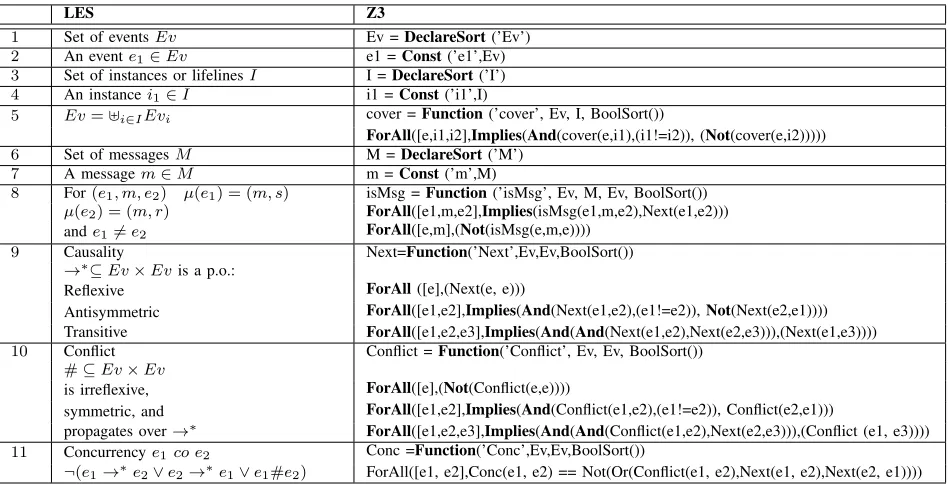
Table 1 shows how the main LES concepts are mapped onto Z3. In particular, a LES is understood here as the semantic model for sequence diagrams as discussed in Sec-tion 3. All main LES noSec-tions including eventsEv, instances I and messages M have a matching new type of element in Z3. This corresponds to creating new types called Ev,
I and M using DeclareSort (rules 1,3,6 in Table 1). Elements of these sets (as event, a message and a lifeline) are mapped onto constants of the corresponding sort (rules 2,4,7). The set of events in a LES used as a semantic model for sequence diagrams defines a partition determined by the set of instances I. This is dealt with in Z3 through a cover function. In particular, if an event e belongs to an instance i1 it cannot belong to a different instance i2
(rules 5). A message is captured in an LES as a triple
(e1, m, e2) such that µ(e1) = (m, s) and µ(e2) = (m, r)
and is captured in Z3 as a functionisM sg that for a triple
(e1, m, e2) determines whether it corresponds to a valid
TABLE 1: How LES for SDs are captured in Z3.
LES Z3
1 Set of eventsEv Ev =DeclareSort(’Ev’)
2 An evente1∈Ev e1 =Const(’e1’,Ev) 3 Set of instances or lifelinesI I =DeclareSort(’I’)
4 An instancei1∈I i1 =Const(’i1’,I)
5 Ev=]i∈IEvi cover =Function(’cover’, Ev, I, BoolSort())
ForAll([e,i1,i2],Implies(And(cover(e,i1),(i1!=i2)), (Not(cover(e,i2)))))
6 Set of messagesM M =DeclareSort(’M’)
7 A messagem∈M m =Const(’m’,M)
8 For(e1, m, e2) µ(e1) = (m, s) isMsg =Function(’isMsg’, Ev, M, Ev, BoolSort()) µ(e2) = (m, r) ForAll([e1,m,e2],Implies(isMsg(e1,m,e2),Next(e1,e2)))
ande16=e2 ForAll([e,m],(Not(isMsg(e,m,e))))
9 Causality Next=Function(’Next’,Ev,Ev,BoolSort())
→∗⊆Ev×Evis a p.o.:
Reflexive ForAll([e],(Next(e, e)))
Antisymmetric ForAll([e1,e2],Implies(And(Next(e1,e2),(e1!=e2)),Not(Next(e2,e1)))) Transitive ForAll([e1,e2,e3],Implies(And(And(Next(e1,e2),Next(e2,e3))),(Next(e1,e3))))
10 Conflict Conflict =Function(’Conflict’, Ev, Ev, BoolSort())
#⊆Ev×Ev
is irreflexive, ForAll([e],(Not(Conflict(e,e))))
symmetric, and ForAll([e1,e2],Implies(And(Conflict(e1,e2),(e1!=e2)), Conflict(e2,e1)))
propagates over→∗ ForAll([e1,e2,e3],Implies(And(And(Conflict(e1,e2),Next(e2,e3))),(Conflict (e1, e3))))
11 Concurrencye1co e2 Conc =Function(’Conc’,Ev,Ev,BoolSort())
¬(e1→∗e2∨e2→∗e1∨e1#e2) ForAll([e1, e2],Conc(e1, e2) == Not(Or(Conflict(e1, e2),Next(e1, e2),Next(e2, e1))))
Furthermore, rules 9, 10 and 11 show how the binary relations between events in a LES are captured in Z3 and in accordance to the LES Definition 1. All relations are captured as functions in Z3 with additional constraints. The rules capture directly all the aspects of the formal definition given. For instance rule 9 shows how to define the partial order, that is, the relation is reflexive, antisymmetric and transitive. Rule 10 describes the conflict relation which is irreflexive, symmetric and propagates over causality.
The concurrency relation in an LES (rule 11) represents an additional binary relation between events. Rather than explicitly defining events in concurrency, any two events not related by causality or conflict are concurrent.
To keep it simple we only show the transformation of the advice model of Figure 3(b) and Figure 4. The Z3 model considered is obtained from the LES of Figure 4.
For each lifeline in the sequence diagram, the transfor-mation generates a constant in Z3 as the snippet of code shows below.
I = DeclareSort(’I’)
//Declaring the lifelines of the advice. User = Const(’User’, I)
PetrolStation = Const(’PetrolStation’, I) Bank = Const(’Bank’, I)
Similarly to what was done for lifelines, for each event in the LES the transformation generates a constant in Z3.
Ev = DeclareSort(’Ev’) //events of lifeline :User e0 = Const(’e0’,Ev) e1 = Const(’e1’,Ev) ...
e71 = Const(’e71’,Ev) e72 = Const(’e72’,Ev)
//events of lifeline :PetrolStation g0 = Const(’g0’,Ev)
g1 = Const(’g1’,Ev) ...
g112 = Const(’g112’,Ev) g111 = Const(’g111’,Ev)
//events of lifeline :Bank l0 = Const(’l0’,Ev)
l1 = Const(’l1’,Ev) ...
l61 = Const(’l61’,Ev) l62 = Const(’l62’,Ev)
The relationship between events and instances/lifelines is dealt with by the functioncover in rule (5). We show it only forUser.
//events of lifeline :User s.add(cover(e0,User)) s.add(cover(e1,User)) s.add(cover(e1,User)) ...
s.add(cover(e71,User)) s.add(cover(e72,User))
For each message in the model, the transformation gen-erates the following constants in Z3.
M = DeclareSort(’M’)
//Defining the set of messages in the advice model ValidPin = Const(’ValidPin’,M)
EnterFuelAmount = Const(’EnterFuelAmount’,M) FuelAmount = Const(’FuelAmount’,M)
CheckAmount = Const(’CheckAmount’,M) BalanceOk = Const(’BalanceOk’,M) StartFuel = Const(’StartFuel’,M) Cancel = Const(’Cancel’,M)
Withdraw = Const(’Withdraw’,M)
The relationship between messages and associated send/receive events is given by the function isM sg given in Table 1 (rule 8). For our advice model example, this is as follows.
s.add(isMsg(g1,ValidPin,e1))
s.add(isMsg(g2,EnterFuelAmount,e2)) s.add(isMsg(e3,FuelAmount,g3)) s.add(isMsg(g4,CheckAmount,l1)) s.add(isMsg(g8,StartFuel,e5))
s.add(isMsg(g10,PaymentDeclined,e6)) s.add(isMsg(l4,Withdrow,g7))
s.add(isMsg(l3,BalanceOk,g6)) s.add(isMsg(l5,Cancel,g9))
Next, we define the relations between the events, namely causality and conflict. Concurrency is generated automati-cally by the solver in accordance to rule 11. The following code shows theUserevents related by causality and conflict. Further causality and conflict relations between other events are obtained automatically through the rules 9 and 10.
s.add(Next(e0,e1)) s.add(Next(e1,e2)) s.add(Next(e2,e3)) s.add(Next(e3,e4)) s.add(Next(e4,e5)) s.add(Next(e4,e6)) s.add(Next(e5,e71)) s.add(Next(e6,e72))
s.add(Conflict(e5,e6))
5.3. Aspect weaving
After producing the Z3 code for the advice, base, and pointcut, we need to create Z3 code that relates them together. This involves creating a set of constraints which identify how base model elements are matched to advice elements in accordance to the pointcut.
There is a wide range of interpretations of how pointcuts should be used to match model elements of the base and advice. Wimmer et al. [24] survey some of these interpreta-tions. To produce the Z3 code thatgluesthe advice and base, any chosen interpretation must be formalised. For example, Klein et al. [4] introduce and formalise four interpretations. These four interpretations describe the degree of strictness when trying to detect a set of model elements which relate to another. For example in Figure 3(c), if we are looking for message validPin followed by startFuel between two lifelines, we can be very strict and assume that the only acceptable match for this is to have the two messages ap-pearing consecutively in a diagram. Alternatively, we can be less restrictive and allow a match provided every occurrence of message validPin happens before startFuel irrespective of the behaviour that may occur in between the messages. Klein et al. refer to the later as the general interpretation. Our implementation follows the general interpretation since this is what our categorical construction in [21] does. It is
possible to replace this and follow any of the other three alternatives, but we would have to redefine the semantics for the composition in that case. Furthermore, choosing for instance the strict interpretation will not allow weaving of the models depicted in Figure 3.
Formal matching has been described for LES earlier (cf. Section 4) through the surjective morphismsfbandfawhere
source and target events have identical labels. We follow the same approach in Z3.
Assume thatM1andM2represent model elements of the base and advice respectively. Model elements of the advice of Figure 3 include validPin and balanceOK. In addition, validPinis also a model element of the base. To distinguish the two we write M1.validPin and M2.validPin instead. Matching can be represented as a boolean partial function matchon the cartesian product of the model elements ofM1 andM2. For instance,match(M1.validPin,M2.validPin) =
true. The value ofmatchcan be obtained from the pointcut model which describes which elements can be matched. The following snippet of Z3 describes the code for matching messages, events and lifelines.
MessageMatch = Function(’MessageMatch’,M,M, BoolSort())
EventMatch = Function(’EventMatch’,Ev,Ev,BoolSort ())
LifelineMatch = Function(’LifelineMatch’,I,I, BoolSort())
ForAll ([ei,ej,en,ek,Mi,Mj],Implies(And(
MessageMatch(Mi,Mj),isMsg(ei,Mi,ek),isMsg(ej, Mj,en)),And(EventMatch(ei,ej), EventMatch(ek, en))))
ForAll ([ei,ej,Li,Lj],Implies(And(EventMatch(ei,ej ),cover(ei,Li),cover(ej,Lj)),LifelineMatch(Li, Lj)))
Above, the first three lines declare boolean valued func-tions for equality of messages, events, and lifelines, re-spectively. The fourth line states that if two messages are matched then their send and receive events are matched as well. As two matched events must belong to matched lifelines, we have the final line. In addition to the above well-definedness criteria, further Z3 code is required to capture the complete definition of the matching morphisms, including how matching preserves configurations (causality and concurrency), and is injective over configurations. One example includes if two events are matched, then any event which follows one of them, will follow the other as well. For space reasons, we omit further rules.
ForAll ([ei,ej,en],Implies(And(EventMatch(ei,ej), Next(ei,en)),Next(ej,en))))
for each pointcut match. This is important because if the repeated occurrences of messages in the base are part of the same configuration, then our morphisms (injective on configurations) force the events associated to these messages to be mapped onto different events in the pointcut.
If all the constraints are satisfiable (outcome of
[image:8.612.314.582.79.199.2]s.check()), the transformation generates a new Z3 model which is a solution representing the result of merging the original models. For our example the model obtained cor-responds to the diagram shown in Figure 5 as expected.
Figure 5: Woven sequence diagram
6. Comparing Z3 and Alloy
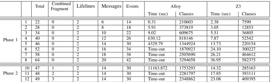
We want to compare the performance of our approach using Z3 with our earlier solutions that used Alloy for sequence diagram composition. For that purpose, we ran 12 experiments, divided in two phases. In Phase 1, we used sequence diagrams without combined fragments. The first experiment of Phase 1 consisted of composing two sequence diagrams each with 4 messages and 2 lifelines. Then, in the following experiments, the number of messages was increased until the composition time was very prolonged.
Table 2 shows the Phase 1 experiments in detail. The results illustrate that increasing the number of sequential messages strongly affected Alloy’s performance.
Overall, this study showed that the maximum number of clauses Alloy can solve is 1753293, taking approximately 3 hours and 10 minutes to produce a solution. However, increasing the number of elements will run out of memory. This is due to the fact that the number of clauses and amount of composition time grows exponentially with respect to the increasing number of sequence diagram elements. The Alloy analyzer is SAT solver-based and SAT-solving time may in-crease enormously, depending on factors such as the number of variables and the average length of the clause [12]. On the
[image:8.612.103.246.191.409.2](a) Composition time in Z3. (b) Composition time in Alloy.
Figure 6: Composition time in Z3 and Alloy
other hand, Z3 showed good performance throughout most of the experiment and increasing the number of messages did not produce any significant effect on its performance (less than 1 minute on average - see Figure 7).
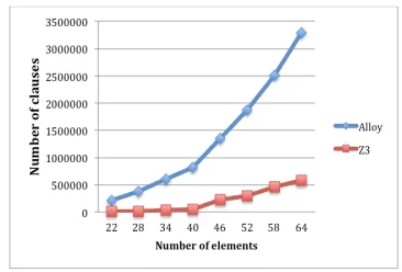
According to Nijjar and Bultan [13], there are several reasons that explain why Z3 performs better than Alloy. First, Z3 uses many heuristics to eliminate quantifiers in formulas. It uses an E-graph to instantiate quantified vari-ables, code trees, and eager instantiation which makes it very effective at dealing with quantifiers [26]. Second, Z3 and Alloy use different implementation languages. For example, Z3 was implemented in C++, while Alloy and its SAT-solver were implemented in Java. Another reason that might make Z3 more efficient is that SMT solvers operate at a higher level of abstraction than SAT solvers. SMT solvers can use information about the structure and semantics of a formula to make the satisfiability process faster whereas a SAT-based approach converts the model to SAT formulas using a Boolean encoding. Due to the increasing size of the Boolean encoding, we then suffer from an exponential increase in composition time. We observed that the Z3-SMT clauses size is much smaller than the one produced by Alloy, which uses a SAT4J solver (see Figure 7).
Figure 7: Number of clauses in Z3 and Alloy for phase 1.
[image:8.612.344.527.513.637.2]com-TABLE 2: Experiments.
Total Combined
Fragment Lifelines Messages Events Alloy Z3 Time (sec) Clauses Time (sec) Clauses
Phase 1
1 22 0 2 6 14 0.31 210603 2.38 7590
2 28 0 2 8 18 5.91 373819 3.05 12853
3 34 0 2 10 22 9.02 609675 5.51 36805
4 40 0 2 12 26 630.12 818146 7.87 52542
5 46 0 2 14 30 4329.79 1344924 13.73 220154
6 52 0 2 16 34 Time-out 1870923 24.10 300227
7 58 0 2 18 38 Time-out 2505690 26.21 464612
8 64 0 2 20 42 Time-out 3294658 36.95 582375
Phase 2
10 47 1 2 14 30 11163.872 1753293 14.32 285163
11 48 2 2 14 30 Time-out 2281797 17.85 393111
12 49 3 2 14 30 Time-out 2348862 23.08 409395
bined fragments was then increased until one of the solvers ran out of memory. Table 2 shows that when messages are structured further through combined fragments, the perfor-mance of Alloy is strongly affected. This study confirms the conclusion of [13], i.e., that Alloy’s performance is affected by the number of variable clauses. Indeed, with an increasing number of combined fragments the performance of Alloy becomes very slow. For examples 11 and 12, Alloy runs out of memory. Z3, on the other hand, had a steady performance throughout and adding a number of combined fragments did not have any significant effect on its performance.
7. Related work
In [16] Ara´ujo and Whittle introduce a tool called MATA for weaving based on sequence diagrams. They put less emphasis on the semantics of composition. Grønmo et al. [8] propose a semantics-based technique for weaving behavioural aspects into sequence diagrams. However, we have a true-concurrent semantics and deal with parallelism in interactions. In later work, Grønmo et al. [15] propose the conformance issue for aspects and ensure that the woven outcome is always the same regardless of the order in which aspects are applied. Moreover, they propose a semantics-based matching, which is looking for matches in the seman-tics of two diagrams. This approach has some similarities to ours, however we use constraint solvers to automatically check consistency of the semantics in the composed model. We have not addressed the order in which aspects are ap-plied, and we do not believe that this will lead to necessarily the same outcome. Whether this can be claimed for a subset of problems remains under investigation.
Klein et al. [4] propose a semantics-based weaver for sequence diagrams. This approach used a number of algo-rithms that allow the detection of join-points which cannot be detected if only the syntax of the model is used. How-ever, this approach did not address how this technique can weaving sequence diagram with complex behaviour such as two sequence diagrams with nested combined fragments.
Reddy et al. [1] use UML sequence diagram templates for describing behaviours of design aspects and use tags for behaviour composition. In their work, an aspect may include position fragments (e.g., begin, end) designating the location to be added in the sequence diagram. Clarke and Walker [27] use UML templates to define aspects. It composes static structural properties of aspects with interaction properties. However, this approach focuses on less complex structures and does not illustrate the methodology of composing inter-action models.
Aspects can sometimes be used to model non-functional concerns such as dependability requirements which usually cut across several parts of the system. Regarding the use of AOM for security, [28] presents a method for the analysis of the performance effects of security properties specified as aspects. Moreover, Whittle et al. [7], uses sequence diagrams to model and execute misuse case scenarios(desired and at-tack scenarios) for secure systems development. Mitigation scenarios are then designed as aspect scenarios and woven into the core behaviour to prevent against the execution of the attack scenarios.
[image:9.612.70.545.88.233.2]8. Conclusion
This paper presents an automated method for aspect weaving of scenario-based models. Although considerable research has been done to weave models, many such ap-proaches are not fully automated. By contrast, in this paper we showed how aspects can be woven automatically with the help of constraint solvers. Amongst the available constraint solvers we decided to use the Z3-SMT solver. Moreover, in this approach, matching and weaving is done at the semantic level since we incorporate the semantics of the models into our transformation algorithm to generate Z3 code.
The example shown in the paper focuses on one base model, one advice and one pointcut. Our approach is not restricted to this and works for any number (of pairwise composed) models. If a solution does not exist it shows that there is an inconsistency between one of the models used. As discussed our weaving follows the general interpretation by [4] which is in accordance to our composition semantics defined in [21].
Finally, our approach should be applicable to a wide range of modelling notation used for design. Although we focus on sequence diagrams and how to capture aspects and aspect weaving, we can similarly use it to compose many different kinds of large static and behaviour models such as class diagrams and state machines.
References
[1] R. Reddy, A. Solberg, R. France, and S.Ghosh, “Composing sequence models using tags,” in Proc. of MoDELS Workshop on Aspect Ori-ented Modeling, 2006.
[2] R. France, I. Ray, G. Georg, and S. Ghosh, “Aspect-oriented approach to early design modelling,”IEE Proceedings-Software, vol. 151, no. 4, pp. 173–185, 2004.
[3] J. Klein, L. H´elou¨et, and J. J´ez´equel, “Semantic-based weaving of scenarios,” inAOSD’06. ACM, 2006, pp. 27–38.
[4] J. Klein, F. Fleurey, and J. J´ez´equel, “Weaving multiple aspects in sequence diagrams,” in Transactions on aspect-oriented software development III. Springer, 2007, pp. 167–199.
[5] OMG,UML: Superstructure. Version 2.4.1, OMG, 2011, document id: formal/2011-08-06.
[6] M. Widl, A. Biere, P. Brosch, U. Egly, M. Heule, G. Kappel, M. Seidl, and H. Tompits, “Guided merging of sequence diagrams,” in SLE 2012, LNCS 7745. Springer, 2013, pp. 164–183.
[7] J. Whittle, D. Wijesekera, and M. Hartong, “Executable misuse cases for modeling security concerns,” in ACM/IEEE 30th International Conference on Software Engineering. IEEE, 2008, pp. 121–130.
[8] R. Grønmo, F. Sørensen, B. Møller-Pedersen, and S. Krogdahl, “Semantics-based weaving of UML sequence diagrams,” in ICMT 2008, LNCS 5063. Springer, 2008, pp. 122–136.
[9] J. Bowles, M. Alwanain, B. Bordbar, and Y. Chen, “Matching and merging scenarios automatically with Alloy,” inModel-Driven Engi-neering and Software Development, CCIS 506. Springer, 2015, pp. 100–116.
[10] J. Bowles, B. Bordbar, and M. Alwanain, “A logical approach for behavioural composition of scenario-based models,” in 17th Inter-national Conference on Formal Engineering Methods, LNCS 9407. Springer, 2015, pp. 252–269.
[11] D. Jackson, Software Abstractions: Logic, language and analysis. MIT Press, 2006.
[12] N. D’Ippolito, M. Frias, J. Galeotti, E. Lanzarotti, and S. Mera, “Alloy+ Hotcore: A Fast Approximation to Unsat Core,” inAbstract State Machines, Alloy, B and Z, LNCS 5977. Springer, 2010, pp. 160–173.
[13] J. Nijjar and T. Bultan, “Unbounded data model verification using SMT solvers,” inIEEE/ACM International Conference on Automated Software Engineering, IEEE, 2012, pp. 210–219.
[14] L. D. Moura and N. Bjørner, “Z3: An efficient SMT solver,” inTACAS 2008, LNCS 4963. Springer, 2008, pp. 337–340.
[15] R. Grønmo, R. Runde, and B. Møller-Pedersen, “Confluence of as-pects for sequence diagrams,”Software & Systems Modeling, vol. 12, no. 4, pp. 789–824, 2013.
[16] J. Ara´ujo and J. Whittle, “Aspect-oriented compositions for dynamic behavior models,” in Aspect-Oriented Requirements Engineering. Springer, 2013, pp. 45–60.
[17] D. Harel and R. Marelly,Come, Let’s Play: Scenario-based Program-ming Using LSCs and the Play-Engine. Springer, 2003.
[18] Z. Micskei and H. Waeselynck, “The many meanings of UML 2 se-quence diagrams: a survey,”Software and Systems Modeling, vol. 10, pp. 489–514, 2011.
[19] J. K¨uster-Filipe, “Modelling concurrent interactions,” Theoretical Computer Science, vol. 351, pp. 203–220, 2006.
[20] G. Winskel and M. Nielsen, “Models for Concurrency,” inHandbook of Logic in Computer Science, Vol. 4, Semantic Modelling, Oxford Science Publications, 1995, pp. 1–148.
[21] J. K. F. Bowles, “Decomposing Interactions,” inAlgebraic Methodol-ogy and Software TechnolMethodol-ogy, LNCS 4019. Springer, 2006, pp. 189– 203.
[22] R. Grønmo and B. Møller-Pedersen, “From UML 2 sequence dia-grams to state machines by graph transformation.”Journal of Object Technology, vol. 10, no. 8, pp. 1–22, 2011.
[23] C. Gonzalez-Perez and B. Henderson-Sellers, Metamodelling for Software Engineering. Wiley, 2008.
[24] M. Wimmer, A. Schauerhuber, G. Kappel, W. Retschitzegger, W. Schwinger, and E. Kapsammer, “A survey on uml-based aspect-oriented design modeling,”ACM Comput. Surv., vol. 43, no. 4, p. 28, 2011.
[25] B. Morin, J. Klein, J. Kienzle, and J.-M. J´ez´equel, “Flexible model element introduction policies for aspect-oriented modeling,” in MOD-ELS, Part II, LNCS 6395. Springer, 2010, pp. 63–77.
[26] L. De Moura and N. Bjørner, “Efficient e-matching for SMT solvers,” inCADE 2007, LNAI 4603. Springer, 2007, pp. 183–198.
[27] S. Clarke and R. J. Walker, “Composition patterns: An approach to designing reusable aspects,” inICSE. IEEE, 2001, pp. 5–14. [28] M. Woodside and et al., “Performance analysis of security aspects by
weaving scenarios extracted from UML models,”Journal of Systems and Software, vol. 82, no. 1, pp. 56–74, 2009.
[29] H. Liang, Z. Diskin, J. Dingel, and E. Posse, “A general approach for scenario integration,” inMoDELS’08, LNCS 5301. Springer, 2008, pp. 204–218.
[30] J. Bowles and B. Bordbar, “A formal model for integrating multiple views,” inACSD 2007. IEEE, 2007, pp. 71–79.
[31] D. Zhang, S. Li, and X. Liu, “An approach for model composition and verification,” in NCM 2009. IEEE Computer Society Press., 2009, pp. 1102–1107.