AND SECURITY APPLICATIONS
Scott L. Cassidy
A Thesis Submitted for the Degree of PhD at the
University of St Andrews
2015
Full metadata for this item is available in Research@StAndrews:FullText
at:
http://research-repository.st-andrews.ac.uk/
Please use this identifier to cite or link to this item:
http://hdl.handle.net/10023/7856
Millimetre-wave FMCW radar for
remote sensing and security
applications
Sco L Cassidy
is thesis is submied in partial fulfilment for the degree of
Doctor of Philosophy
at the University of St Andrews
Abstract
is thesis presents a body of work on the theme of millimetre-wave FMCW radar, for the purposes of security screening and remote sensing.
First, the development of an optimised soware radar signal processor will be outlined. rough use of threading and GPU acceleration, high data processing rates were achieved using standard PC hardware. e flexibility of this approach, compared to specialised hardware (e.g. DSP, FPGA etc…), allowed the processor to be rapidly adapted and has produced a significant performance increase in a number of advanced real-time radar systems. An efficient tracker was developed and was successfully deployed in live trials for the purpose of real-time wave detection in an autonomous boat control system.
Automated radar operation and remote data telemetry functions were im-plemented in a terrain mapping radar to allow continuous monitoring of the Soufrière Hills volcano on the Caribbean island of Montserrat. is work con-cluded with the installation of the system 3 km from the volcano.
Hardware modifications were made to enable coherent measurement in a number of existing radar systems, allowing phase sensitive measurements, in-cluding range-Doppler, to be performed. Sensitivity to displacements of less than 200 nm was demonstrated, which is limited by the phase noise of the system. Effi-cient compensation techniques are presented which correct for quadrature mixer imbalance, FMCW chirp non-linearity, and scanner drive distortions.
In collaboration with the Home Office, two radar systems were evaluated for the stand-off detection of concealed objects. Automatic detection capability, based on polarimetric signatures, was developed using data gathered under con-trolled conditions. Algorithm performance was assessed through blind testing across a statistically significant number of subjects. A detailed analysis is pre-sented, which evaluates the effect of clothing and object type on detection effi-ciency.
Declarations
1. Candidate’s declarations
I, Sco L Cassidy, hereby certify that this thesis, which is approximately 44,000 words in length, has been wrien by me, and that it is the record of work carried out by me, or principally by myself in collaboration with others as acknowledged, and that it has not been submied in any previous application for a higher degree.
I was admied as a research student in September 2010 and as a candidate for the degree of Doctor of Philosophy in September 2011; the higher study for which this is a record was carried out in the University of St Andrews between 2010 and 2015.
Date: Signature of candidate:
Sco L Cassidy
2. Supervisor’s declaration
I hereby certify that the candidate has fulfilled the conditions of the Resolution and Regulations appropriate for the degree of Doctor of Philosophy in the Uni-versity of St Andrews and that the candidate is qualified to submit this thesis in application for that degree.
Date: Signature of supervisor:
Dr Duncan A Robertson
Date: Signature of supervisor:
Dr Graham M Smith
In submiing this thesis to the University of St Andrews I understand that I am giving permission for it to be made available for use in accordance with the regu-lations of the University Library for the time being in force, subject to any copy-right vested in the work not being affected thereby. I also understand that the title and the abstract will be published, and that a copy of the work may be made and supplied to any bona fide library or research worker, that my thesis will be electronically accessible for personal or research use unless exempt by award of an embargo as requested below, and that the library has the right to migrate my thesis into new electronic forms as required to ensure continued access to the the-sis. I have obtained any third-party copyright permissions that may be required in order to allow such access and migration, or have requested the appropriate embargo below.
e following is an agreed request by candidate and supervisor regarding the publication of this thesis:
• No embargo on the printed copy
• No embargo on the electronic copy
Date: Signature of candidate:
Sco L Cassidy
Date: Signature of supervisor:
Dr Duncan A Robertson
Date: Signature of supervisor:
Dr Graham M Smith
Acknowledgements
I would like to thank the following individuals for their help and support through-out the research and writing of this doctoral thesis:
My primary supervisor, Dr Duncan Robertson, for making this PhD both educational and enjoyable, and for his support and guidance throughout. I would also like to thank Duncan for his advice during the writing of this thesis and for proofreading the manuscript.
My second supervisor, Dr Graham Smith, for his support and encourage-ment over the years. I would also like to thank Graham for his advice during the writing of this thesis and for proofreading the manuscript.
Dr David Macfarlane for making my work with AVTIS and SAFIRE enjoy-able and productive.
Dr David Bolton for his advice and insight on the subject of electronics.
I would also like to thank the rest of the millimetre-wave group, past and present, for their assistance and for making this an enjoyable place in which to work: Dr Robert Hunter, Dr Paul Cruickshank, Dr Peter Speirs, Dr Hassane El Mkami, Dr Tom Gallacher, Johannes McKay and Claire Motion.
I would like to thank my family for all of their support and encouragement.
I would also like to acknowledge the Natural Environment Research Council for providing funding for this PhD.
Publications
e following publications incorporate work which is outlined within this thesis:
D. A. Robertson, S. L. Cassidy, B. Jones, A. Clark. Concealed threat detection with the IRAD sub-millimeter wave 3D imaging radar, Proc. SPIE, Passive and Active Millimeter-Wave Imaging XVII (9 June 2014)
D. A. Robertson, S. L. Cassidy. Micro-doppler and vibrometry at millimeter and sub-millimeter wavelengths, Proc. SPIE, Radar Sensor Technology XVII (31 May 2013)
D. A. Robertson, S. L. Cassidy, D. R. Bolton. Nonlinearity and phase noise effects in 340 GHz 3D imaging radar, Proc. SPIE, Passive and Active Millimeter-Wave Imaging XVI (31 May 2013)
D. G. Macfarlane, D. A. Robertson, S. L. Cassidy, H. M. Odbert, M. R. James,H. Pinkerton, G. Wadge. Passive and active imaging at 94 GHz for environmental remote sensing, Proc. SPIE, Passive and Active Millimeter-Wave Imaging XVI (31 May, 2013)
D A. Robertson, P. N. Marsh, D. R. Bolton, R. J. C. Middleton, R. I. Hunter, P. J. Speirs, D. G. Macfarlane, S. L. Cassidy, G. M. Smith. 340-GHz 3D radar imaging test bed with 10-Hz frame rate, Proc. SPIE, Passive and Active Millimeter-Wave Imaging XV (1 May, 2012)
P. J. Speirs, D. G. Macfarlane, S. L. Cassidy, P. D. Cole, M. J. Froude, and D. A. Roberston. Reflectivity measurement of rain using a 94 GHz radar,35th Confer-ence on Radar Meteorology (26 September 2011)
Acronyms
ADC Analogue to digital converter
ANSI American National Standards Institute API Application programming interface
AVTIS All-terrain Volcano Topography Imaging Sensor AVX Advanced vector extensions
BMI Body mass index
CMOS Complementary metal-oxide-semiconductor CPU Computer processing unit
CUDA Compute unified device architecture DAC Digital to analogue converter
DAQ Digital acquisition DC Direct current
DDS Direct digital synthesiser DEM Digital elevation map DFT Discrete Fourier transform DIP Dual-inline package DSP Digital signal processor FFT Fast Fourier transform
FFTW Fastest Fourier Transform in the West (FFT library) FMCW Frequency modulated continuous-wave
FN False negative FNR False negative rate FOD Foreign object debris FP False positive
FPGA Field-programmable gate array FPR False positive rate
GCC GNU Compiler Collection
GLSL (Open)GL shader language GOLA Gaussian optics lens antenna GPS Global Positioning System GPU Graphics processing unit IF Intermediate frequency IP Internet protocol
IRAD Imaging RADar
ISP In-system programming LO Local oscillator
MVO Montserrat Volcano Observatory NIRAD Non-Imaging RADar
OMT Orthomode transducer
PC Personal computer
PCB Printed circuit board
PCI Peripheral Component Interconnect PLL Phase-locked loop
PM-YTO Permanent magnet YIG-tuned oscillator PPI Plan position indication
PSUCB Power supply unit and control box PXI PCI extensions for instrumentation RCS Radar cross-section
RF Radio frequency
RGBA Red green blue alpha RMS Root mean square
ROC Receiver operator characteristic
RX Receive
SAFIRE St Andrews Fast Imaging Radar Equipment SAR Synthetic aperture radar
SIMD Single instruction multiple data SMA Subminiature version A (connector) SNR Signal-to-noise ratio
SSE Streaming SIMD extensions STALO Stable local oscillator
TCP Transmission control protocol
TN True negative
TP True positive TPR True positive rate
TTL Transistor-transistor logic
TX Transmit
UART Universal asynchronous receiver/transmier USB Universal serial bus
VCO Voltage controlled oscillator
VCVA Voltage controlled variable aenuator VHDL VHSIC Hardware Description Language VHSIC Very high speed integrated circuit YIG Yrium iron garnet
Contents
1 Introduction 1
1.1 Overview . . . 1
1.2 Frequency modulated continuous wave radar . . . 1
1.3 Millimetre-wave radar . . . 5
1.4 Examples of millimetre-wave FMCW radar . . . 6
1.4.1 Volcano terrain mapping . . . 7
1.4.2 Runway debris detection . . . 8
1.4.3 Stand-off detection of concealed weapons . . . 10
1.4.4 Automotive radar . . . 12
1.4.5 Mining applications . . . 13
1.5 Signal processing techniques . . . 14
1.5.1 CPU-based processing . . . 15
1.5.2 GPU-based processing . . . 15
1.5.3 Digital signal processors . . . 16
1.5.4 Field-programmable gate arrays . . . 16
1.5.5 Optimal method . . . 17
1.6 Summary . . . 17
2 Soware signal processor 21 2.1 Introduction . . . 21
2.2 Processing routine . . . 21
2.3 Processing hardware . . . 22
2.4 readed programming . . . 23
2.4.1 Multi-core processors . . . 23
2.4.2 Multi-tasking . . . 24
2.4.3 Programming complexity . . . 24
2.4.4 Implementation . . . 25
2.4.6 ADC thread . . . 26
2.4.7 Worker threads . . . 27
2.4.8 Render threads . . . 28
2.5 Colour-scaling . . . 28
2.5.1 CPU-based method . . . 28
2.5.2 GPU colour-scaling . . . 31
2.6 OpenGL integration . . . 32
2.7 FFT libraries . . . 32
2.8 C compiler . . . 34
2.9 Benchmarking thread performance . . . 35
2.10 Overall performance . . . 35
2.11 Data storage . . . 36
2.12 Conclusions . . . 36
3 NIRAD and IRAD 38 3.1 Introduction . . . 38
3.2 NIRAD . . . 39
3.3 IRAD . . . 40
3.4 Enabling coherent measurement . . . 42
3.5 Evaluating phase sensitivity . . . 47
3.6 Vibrometry . . . 52
3.7 Micro-Doppler measurements . . . 53
3.7.1 eory . . . 53
3.7.2 Measurement . . . 54
3.7.3 Processing . . . 54
3.7.4 Micro-Doppler . . . 57
3.8 Mirror drive correction in IRAD . . . 58
3.8.1 Introduction . . . 58
3.8.2 Hardware . . . 58
3.8.3 Method . . . 59
3.8.4 Results . . . 60
3.9 IQ-mixer imbalance . . . 61
3.9.1 eory . . . 61
3.9.2 Mixer characterisation . . . 62
3.9.3 Target characterisation . . . 64
3.9.5 Results . . . 65
3.10 Chirp non-linearity . . . 66
3.10.1 eory . . . 66
3.10.2 Phase error calibration . . . 67
3.10.3 Testing . . . 69
3.10.4 Application to non-coherent radar . . . 72
3.10.5 Application to non-quadrature data . . . 72
4 Concealed object detection 75 4.1 Background . . . 75
4.2 Overview . . . 76
4.3 IRAD . . . 77
4.4 Trial structure . . . 78
4.5 Compliant screening . . . 79
4.6 Algorithmic detection . . . 85
4.6.1 Polarisation signatures . . . 85
4.6.2 Spatial signatures . . . 87
4.6.3 Algorithm design . . . 87
4.6.4 Algorithm implementation . . . 89
4.6.5 Trial two . . . 91
4.6.6 Single person compliant results . . . 91
4.7 Measurement of multiple subjects . . . 96
4.7.1 Introduction . . . 96
4.7.2 Method . . . 96
4.8 Assessment of IRAD performance . . . 98
4.8.1 Overview . . . 98
4.8.2 Automatic scoring . . . 99
4.8.3 Analysis . . . 100
4.8.4 Clothing effects . . . 105
4.8.5 High throughput screening . . . 107
4.9 Conclusions . . . 109
4.9.1 System performance . . . 109
4.9.2 Detection signatures . . . 110
4.9.3 Clothing . . . 111
4.9.4 Future work . . . 111
5.1 Introduction . . . 113
5.2 Integration of soware processor . . . 115
5.2.1 Overview . . . 115
5.2.2 GPU processing . . . 115
5.2.3 Results . . . 117
5.3 Outreach installation . . . 117
5.4 Wave tracking . . . 119
5.4.1 Overview . . . 119
5.4.2 Car radar . . . 119
5.4.3 Algorithm overview . . . 120
5.4.4 Development of a tracking algorithm . . . 121
5.4.5 Beam integration . . . 121
5.4.6 Filtering . . . 121
5.4.7 Optimised median filtering . . . 122
5.4.8 Peak detection . . . 124
5.4.9 Tracking . . . 124
5.4.10 Alpha-beta tracker . . . 127
5.4.11 Alternative filters . . . 128
5.4.12 Evaluation and tuning . . . 128
5.4.13 Live testing . . . 130
5.5 Conclusions . . . 131
6 AVTIS 132 6.1 Introduction . . . 132
6.2 Operation . . . 133
6.2.1 Overview . . . 133
6.2.2 AVTIS-2 . . . 133
6.2.3 AVTIS-3 . . . 133
6.2.4 Reference reflectors . . . 134
6.2.5 Digital elevation map (DEM) generation . . . 134
6.3 Fieldwork . . . 135
6.3.1 Summary . . . 135
6.3.2 Deployment . . . 135
6.3.3 First field trip . . . 137
6.3.4 Second field trip (AVTIS-3 installation) . . . 138
6.4 Control soware . . . 141
6.4.1 Processing enhancements . . . 141
6.4.2 Scheduling . . . 141
6.4.3 File transfer requirements . . . 142
6.4.4 File transfer design . . . 142
6.4.5 File transfer performance . . . 144
6.5 Rain . . . 145
6.5.1 Overview . . . 145
6.5.2 Data logger . . . 145
6.6 Clock generator . . . 148
6.6.1 Introduction . . . 148
6.6.2 Redesigned clock generator . . . 149
6.6.3 USB control . . . 150
6.6.4 USB programming . . . 150
6.6.5 On-board oscillator . . . 150
6.6.6 Trigger generator . . . 151
6.6.7 Aenuator and power monitor . . . 151
6.6.8 Integration . . . 152
6.6.9 Coherent operation . . . 153
6.7 Conclusions . . . 154
7 Conclusions and future work 156 7.1 Summary . . . 156
7.2 Soware signal processor . . . 156
7.3 Compensation techniques . . . 157
7.4 Real-time tracking . . . 158
7.5 Coherent measurement . . . 158
7.6 Concealed object detection . . . 159
7.7 Autonomous radar operation . . . 160
8 Bibliography 161
Chapter 1
Introduction
1.1 Overview
e doctoral work which will be outlined in this thesis encompasses a number of distinct, yet closely related areas and themes within modern millimetre-wave FMCW radar. From the outset, this body of research has been conducted with a clear vision towards advancing the use of millimetre-wave radar for the appli-cations of remote-sensing of the natural environment, and in stand-off detection of concealed objects. is work charts a path through the development of radar timing circuitry, high performance signal-processing techniques, fieldwork and large-scale experimental trials, culminating in the analysis and statistical interpre-tation of the resultant radar output. is introductory chapter will outline the un-derlying principles, techniques and applications of millimetre-wave FMCW radar and will provide the context, into which this work fits, within the wider body of research representing the current state of the art.
1.2 Frequency modulated continuous wave radar
A radar, in its most basic sense, is an apparatus which determines the range and/or velocity of a target, or series of targets, by the correlation of a transmied radio-wave signal with its time-delayed reflection. Much of the initial radar research took place both prior to and during the Second World War, spurred on by a clear defensive military need for aircra and ship detection at distance [1]. ese early systems were almost all pulsed radars, which transmit a temporally-short high-power radio signal and then listen for the much smaller returned echoes. In a
simple pulsed radar, the correlation in question is a time measurement between the transmied pulse and the received echo. is thesis, however, concerns the application of a different class of radar system, thefrequency modulated continu-ous wave radar, which will henceforth be referred to as FMCW radar.
[image:17.595.189.430.193.258.2]ADC R
Figure 1.1: Simplified diagram of a single antenna FMCW radar with a single target at distanceR.
Figure 1.1 shows a simplified diagram of a single antenna FMCW radar with a single target at distanceR. In contrast to pulsed radars, FMCW radars trans-mit and receive simultaneously during acquisition and utilise a source which is modulated in frequency. is modulation is typically a linear frequency ramp, in which case the target return lags the transmied signal by a frequency pro-portional to the time-of-flight. e radar return signal is subsequently down-converted against the transmit signal to produce an intermediate frequency (IF) output. A discrete Fourier transform of this IF signal produces a frequency spec-trum, directly interpretable as a range profile. e power received from a point target is given by the following equation:
PR=
PTGRGTσ λ2
(4π)3R4 (1.1)
Where PR is the received power,PT is the transmied power,GR is the receive
antenna gain,GTis the transmit antenna gain,σ is the radar cross-section,λ is
the operating wavelength, andRis the range to target. eR4dependence is due to the two-way propagation of the radar beam.
Each individual frequency sweep is commonly referred to as a chirp. While many FMCW radars do transmit continuously with zero inter-chirp delay, a radar which does not transmit for a period of time between chirps would still be con-sidered to be FMCW. Figure 1.1 shows a simplified diagram of a single antenna FMCW radar.
ere are a number of benefits to FMCW radar in comparison to pulsed radar which will be outlined below:
signal is reflected back to the radar. Since pulsed radars transmit only for a short period of time, the peak transmit power is high relative to the mean transmit power. is typically requires using large, heavy, inefficient, high voltage vacuum components. In comparison, the continuous transmission of FMCW means that the same average transmit power can be achieved using a significantly smaller peak power. is allows FMCW radars to be built using lower cost, efficient solid state components [2]. Low power con-sumption means that FMCW radars may be easily powered by baeries or solar panels in portable or remote deployment [3].
• High range resolution:e range resolution of a radar determines the min-imal separation for which two distinct targets may be distinguished. In a simple pulsed radar higher range resolution is achieved by shortening the pulse duration, thereby increasing the bandwidth of the pulse. However, component switching time and the need to further increase transmit power limit the achievable range resolution. Analogously, the range resolution of an FMCW radar is determined solely by the bandwidth of the chirp, inde-pendent of the chirp duration which permits fine range resolution to be achieved.
• Short range measurement: Pulsed radars do not transmit and receive si-multaneously and therefore have a minimum measurement range, which results from the combination of pulse duration and switching time. FMCW radars, in contrast transmit and receive simultaneously and are capable of very short minimal measurement ranges. In practice, the presence of a large DC component in the demodulated FMCW IF, which must be filtered to prevent amplifier saturation, limits the minimum measurement range in an FMCW system. Measurement of ranges on centimetre scales is possible in a well-designed FMCW radar.
the bandwidth as a percentage of the carrier frequency is smaller, given an equal range resolution. is is important, since the difficulty of engineering RF components generally depends on percentage bandwidth, rather than the absolute bandwidth.
• Arbitrary irp duration: In a simple pulsed radar, pulse duration and pulse bandwidth are inversely proportional. In the case of FMCW radar, chirp duration and chirp bandwidth are completely independent. Chirp duration may be increased arbitrarily while maintaining a fixed range res-olution. is allows good signal-to-noise to be achieved while maintaining low transmit power in order to limit power consumption, to reduce the likelihood of causing interference or to reduce the probability of intercep-tion [4].
Of course, these benefits come at the expense of several disadvantages:
• Range-velocity ambiguity: Since range to target is encoded in frequency, any Doppler shi introduced due to target movement alters the apparent target range. Radially translating targets will display an error in observed position and rotating targets will result in a spreading of the target’s range peak. is ambiguity can be removed by comparing the phase progression of a target across a series of consecutive chirps. is technique also permits moving targets to be isolated from within a larger stationary background.
• Chirp non-linearity: While range-resolution is determined by the chirp bandwidth, any deviation from a perfectly linear frequency ramp will cause the target-induced IF frequency to vary across the duration of the chirp, de-grading the range-resolution of the radar. ere are a number of hardware and soware compensation techniques which may be used to address this issue.
and may be more desirable for compact systems. In single antenna designs, separation of transmit and receive paths is achieved by the use of an RF circulator. However, antenna and circulator leakage typically remains as the dominant cause of receiver sensitivity loss. ere are a number of tech-niques available to suppress this leakage in order to achieve good perfor-mance in single antenna radars [6, 7].
• Minimum irp duration: Since FMCW radar down-converts the received radar return against the original transmission, it is necessary that the two signals overlap significantly. is means that chirp duration must be much greater than the round-trip time, placing an upper limit on the chirp repe-tition rate. In phase-coherent radars where each chirp is phase-consistent with the previous one it may be possible to down-convert radar returns from the previous chirp with the transmied signal of the current chirp. is would result in a potential ambiguity in range.
1.3 Millimetre-wave radar
While many of the techniques discussed within this thesis apply generally to FMCW radar at any operating frequency, all of the experimental work was under-taken using radars which operate using millimetre-waves. e millimetre-wave spectrum is loosely defined as the spectral region between the wavelengths of 10 mm and 1 mm, or the frequencies of 30 GHz and 300 GHz respectively. e choice of operating frequency represents a trade-off as each spectral region offers different advantages and disadvantages, which can be broadly grouped under one of the following categories:
• Spatial resolution: For a fixed aperture size, a higher operating frequency results in a beam with a smaller angular size.
• Range resolution:e range resolution of an FMCW radar is determined by the chirp bandwidth. A higher range resolution is more easily achievable at a higher operating frequency, because a given chirp bandwidth represents a smaller percentage variation of the carrier.
• Material penetration: e ability for the directed beam to penetrate a ma-terial, varies depending on the material in question. As is the case with atmospheric aenuation, lower frequencies can generally penetrate deeper into a material.
is thesis concerns two areas of application: remote sensing of the natural environment and the scanning of persons for the detection of concealed threats. e use of millimetre-wave radar in these circumstances represents a compromise between the good material propagation properties of microwave radar, and high-resolution optical ranging techniques, such as Lidar.
For short range environmental mapping, Lidar is a well established measure-ment technology. Lidar, an optical analogue of radar, offers high spatial reso-lution, in a compact system with a relatively low cost. Such systems utilise a laser source and typically operate in the infrared. However, measurement range is severely degraded in the presence of dense airborne obscurants such as dust, ash, or fog. In environments where measurement is precluded by low optical visibility, millimetre-wave radar can provide the propagation characteristics and spatial resolution necessary to permit measurement.
Millimetre-wave systems are increasingly seeing large adoption in security screening applications, routinely installed in sensitive installations such as air-ports. Typical airport scanners, such as the ProVision ATD from L-3 SDS, employ an enclosed booth with an active millimetre wave imager. ere are a number of research radar systems which are designed to operate at larger stand-off distances. Millimetre-waves are uniquely suited for human screening because of their abil-ity to detect threat objects concealed below clothing. As millimetre-waves are a form of non-ionising radiation, their use is considered to be completely safe at legally-permied transmit powers [8,9]. As individuals rightly have the expecta-tion of personal privacy, automated classificaexpecta-tion algorithms are used to analyse captured imagery in such systems.
1.4 Examples of millimetre-wave FMCW radar
• Remote sensing: ground-based terrain mapping of volcanoes [3, 10, 11], airborne thickness profiling of ice [12–14], airborne terrain mapping using synthetic aperture radar (SAR) [15, 16]
• Security: detection of concealed weapons [17–20], perimeter surveillance [21]
• Industrial: assisted vision in mining environments [22–25], silo depth sen-sors [26, 27]
• Aeronautical:low visibility radar assisted landing of aeroplanes [28], detec-tion of suspended cables [29–31], assisted landing for helicopters in dusty environments [32], detection of foreign object debris on runways [33–37]
• Automotive: autonomous navigation [38], low-cost integrated radar mod-ules for parking sensors, cruise control and collision avoidance [39–43]
• Meteorological:cloud profiling [44], short-range measurement of rain and related weather phenomena [45]
e aim of this section is to provide an overview of the broad range of appli-cations which represent the current state-of-the-art, many of which are relevant to the research presented in this thesis.
1.4.1 Volcano terrain mapping
On 18th July 1995, the Soufrière Hills volcano on the Caribbean island of Montser-rat, a British Overseas Territory, erupted aer a period of prolonged dormancy. e island’s Georgian-era capital city of Plymouth was destroyed in the initial eruption and in subsequent eruptions during the years that followed. While the number of casualties has fortunately remained low, the volcano continues to have a major adverse effect on the island’s population. While more than half of the is-land is covered by an exclusion zone, residents outside of this area are still subject to evacuation during periods of eruption. e ability to monitor volcanic activity in order to understand and predict risk is of utmost importance in safeguarding the population, while minimising the disruption to everyday life.
monitor the rapidly changing topography of the volcano’s lava dome. At this operating frequency it is capable of penetrating the environmental obscurants which frequently cloak the underlying terrain, while maintaining a good spatial resolution. Orographic clouds which result from interactions between the air and the terrain itself are the principle cause of this loss in optical visibility. By monitoring the changing topography of the dome, the rate of growth can be deter-mined and it is hoped that this will aid in the prediction of future dome collapse. In addition to a radar, AVTIS also functions as a passive millimetre-wave imager, allowing thermal images to be acquired, despite a lack of optical visibility. Since the radar and passive imager share a common antenna, radar topography and thermal imagery may be trivially co-registered.
ere are two current incarnations of AVTIS, which both share a common design:
• AVTIS-2: A mobile surveying instrument with a 45 cm Cassegrain antenna. e radar and its control computer can operate for many hours using stan-dard 12 V lead-acid baeries.
• AVTIS-3: A permanently installed and fully automated instrument with a smaller 30 cm Cassegrain antenna. Currently situated approximately 3 km from Soufrière Hills. Recorded data is transferred to the Montserrat Vol-cano Observatory by standard 802.11 wireless networking with a high gain antenna link. e radar, control computer and communication hardware are powered by solar panels.
A millimetre-wave radar, such as AVTIS, is ideally suited to this type of ap-plication when compared to other common surveying techniques. Commercially available Lidar surveys, while providing useful information about the surround-ing topography, consistently fail to map the topography of the lava dome itself. Furthermore, significant terrain changes may occur from one day to the next during periods of activity. ermal imaging cameras can provide some useful indication of activity based on surface temperature, but are similarly adversely affected by optical obscurants.
1.4.2 Runway debris detection
flight 4590, where a piece of debris which had become detached from another air-cra caused a tyre to rupture during take off. e resultant damage to one of the fuel tanks and the consequent failure of two engines caused the plane to crash less than two minutes aer take off. All 109 passengers and crew, as well as 4 persons on the ground, were killed.
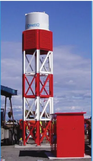
[image:24.595.228.392.395.677.2]e item of debris which caused the accident measured 435 mm in length. While airport protocol in place at the time of the accident required that a manual runway inspection be performed prior to take-off of a Concorde, on this occasion the required inspection was not completed. e loss of flight 4590 highlighted the danger posed by the presence of FOD. In the aermath of the accident, QinetiQ began development of the Tarsier runway debris detection radar, a dual-antenna 94 GHz FMCW radar system [34]. Tarsier features an asymmetric Gregorian an-tenna, resulting in an azimuth-confined fan beam which can be quickly scanned across the entire runway. While manual inspections are slow, labour-intensive and extremely prone to human error, Tarsier can perform a scan of a runway
prior to every take-off or landing and is specified to detect objects as small as a single M12 bolt.
In the case of Tarsier, antenna leakage is controlled by the use of separate transmit and receive antennas. However, it is well known that phase noise leak-age from large reflectors in a scene can also result in a severe degradation to the receiver noise floor [46]. is typically manifests itself as a radial streak along the entire range profile when the beam strikes a target with a large radar cross-section. is is a particularly acute problem in the case of radars such as Tarsier, where very small objects must be detected in the presence of considerably larger background cluer. In such measurement conditions, the use of low phase noise sources is critical to achieving a good detection performance. For further discus-sion of the impact of reflected phase noise, in phase sensitive measurement, see section 3.5.
While Tarsier has been the most successful system designed for this applica-tion, there are other radars which are designed for this purpose [35–37].
1.4.3 Stand-off detection of concealed weapons
e ability to screen civilians for concealed weapons or explosives in public places is increasingly perceived as an important capability for use by security agencies and law enforcement. While there are a number of established and emerging technologies, both passive and active, for close-range screening of individuals in a checkpoint scenario, mid to long-range screening presents a considerably greater challenge. is is mainly due to the large antenna sizes required to obtain a suf-ficiently narrow beam profile at distance. is requirement can be somewhat mitigated by operating at higher frequencies in the sub-millimetre wave band, from 300-1000 GHz. Such capabilities are highly desirable in the context of non-cooperative screening of crowded public gatherings, perimeter security, high-throughput checkpoint scenarios or where clandestine operation is required.
by Ken Cooper at NASA’s Jet Propulsion Lab (JPL) have demonstrated FMCW radar systems operating at 580 GHz [47], 675 GHz [48], and most recently at 340 GHz [18], with a bandwidth of 30 GHz. e resultant fine range resolution per-mits multiple reflections due to clothing layers to be resolved, and the profile of a concealed object to be resolved, as shown in figure 1.3. eir current 340 GHz system is capable of operation at a frame rate of up to 4 Hz, at a stand-off distance of 7 m. A 350 GHz system has also been reported by a team led by David Sheen at Pacific Northwest National Laboratory [19, 20].
Figure 1.3:Detection of front return due to subject’s clothing and a back reflection showing a concealed pistol for a subject at a stand-off distance of 4 m. Acquisition time of 6 minutes. Image reproduced from [49].
1.4.4 Automotive radar
e potential of millimetre-wave radar in active driver assist systems has long been recognised, and has been the subject of research and development efforts since the early 1970s [53]. Since the late 90s, advances in computing power and the emergence of lower cost millimetre-wave components have converged to make car radar systems a viable mass-market technology.
e functions enabled by automotive radar broadly fall into two categories:
• Driver convenience: Parking assistance to alert the driver of obstacles out-side of their field of view and adaptive cruise control to allow the car to match the speed of nearby vehicles.
• Safety: Collision detection and mitigation either to provide advance warn-ing to the driver of a likely collision or to take automatic action in order to either avoid low speed collisions altogether or reduce the severity of mid-to-high speed collisions.
Automotive radar systems usually comprise a short-range wide band radar operating at either 22-26 GHz or 77-81 GHz and a long range radar operating at 76-77 GHz [42]. Millimetre-wave radar is advantageous in this application, in comparison to optical techniques such as camera or laser based solutions, due to its ranging capability, ability to operate in adverse weather conditions and the possibility for it to be concealed behind opaque bodywork for aesthetic reasons.
Automotive radar is the only current mass-market application of millimetre-wave radar, and modules are produced by a number of companies including Bosch, Smartmicro and Freescale. e size of the market allows highly integrated mod-ules to be produced with a typical unit cost of around $50 USD.
manufac-turing technology to a new application would more economically viable, when compared to the expense of developing a completely new radar architecture.
1.4.5 Mining applications
[image:28.595.171.448.352.628.2]e efficiency of modern mining operations is the result of a trend towards heavy mechanisation and a lower reliance on human labour. In this type of environ-ment, such heavy excavation generates substantial volumes of dust which results in extremely low visibility even at close range. Low optical visibility in this envi-ronment greatly reduces operator visibility resulting in reduced efficiency and a negative impact on safety. Millimetre-wave FMCW radar systems have a demon-strated utility as an augmented vision system within the mining industry, in op-erations both above-ground and below-ground [22–25].
Figure 1.4:Imagery showing a photograph of a drag-line (le) and the correspond-ing radar imagery (right). Image reproduced from [23].
of a drag-line. e radar imagery permits an operator to monitor the terrain and fill level of the bucket, permiing operation even when there is no optical visibility. In below-ground operations a radar system can measure the quantity of material moving through a mine sha and to determine the topography of newly excavated cavities. Such radar systems have been demonstrated with the capability to penetrate dust levels in excess of those normally expected to be encountered, up to a level of 4 kg/m³.
1.5 Signal processing techniques
One early application of FMCW radar was in radio altimeters where a reflection is obtained from a single target. FMCW systems capable of resolving multiple targets were severely hampered by a lack of signal processing capability [1]. e emergence of the fast Fourier transform in the 1960s [54] as well as advances in computing were responsible for making FMCW a viable technology. As modern high-performance FMCW radars present a considerable computational load, ef-ficient signal processing routines are required in order to achieve high system performance. ere are a great many technologies available to satisfy this pro-cessing requirement [55]. ese include:
• Conventional general-purpose CPU-based processing
• GPU-based computation, implemented using CUDA/OpenCL/GLSL/HLSL
• Specialised digital signal processing (DSP) hardware
• Field-programmable gate arrays (FPGAs)
by dividing execution between multiple processors, the number of mathematical operations performed each second may be increased. Each of the options outlined above offer some degree of parallelism, which will be discussed and contrasted below.
1.5.1 CPU-based processing
e general-purpose CPUs found in conventional personal computers are de-signed to perform well in a wide range of operations, but are not specifically tuned for any particular task. With today’s focus on energy efficiency, and a need to control the amount of heat which must be dissipated, these convention-ally non-parallel devices now offer several different methods of performing par-allel operations.
e first of these techniques permits the same operation to be executed on multiple pieces of data. ese processor instructions are given the name Single Instruction Multiple Data (SIMD). e various generations of Intel’s Streaming SIMD Extensions (SSE) provide 128-bit registers and permit operations to be per-formed simultaneously on four 32-bit floating point numbers, or two 64-bit float-ing point numbers [56]. e modern successor to SSE, the Advanced Vector Ex-tensions (AVX) currently provides 256-bit registers for operation on eight 32-bit floats or four 64-bit floats. Processors scheduled for delivery in 2015 will further double this operation count by providing 512-bit registers.
e other technique available to a programmer is multi-core processing. Mod-ern processors equipped with multiple processing cores are capable of simultane-ously handling of a number of threads of execution, each one independent of the others. is independence comes as both a blessing and a curse, as one is free to simultaneously execute distinct tasks while burdened with the need to manually coordinate the state of each independent thread [57]. is can be the source of particularly insidious concurrency-related bugs which manifest infrequently and can be very difficult to diagnose and remedy.
1.5.2 GPU-based processing
op-eration resulting in a complete scene projected onto a two-dimensional screen. Early graphics processors featured fixed rendering pipelines, with a limited selec-tion of texturing and lighting opselec-tions. Support for programmable shaders later allowed a programmer to take control of various parts of the rendering pipeline, allowing arbitrary creative visual effects to be realised. Non-graphics process-ing operations are also possible usprocess-ing programmable shaders in OpenGL [58,59], programmed using OpenGL shading language (GLSL) [60–62]. However, the util-ity of graphics acceleration hardware for a larger range of non-graphics calcula-tions did not escape the aention of those within the graphics industry. Modern graphics cards now offer complete access to the highly-vectorised processor ar-chitecture beyond what is possible using programmable shaders, through either nVidia’s dominant yet proprietary CUDA programming interface [63], or through the open industry standard OpenCL interface [64].
Despite clock speeds which are typically considerably lower than conven-tional CPUs, a GPU offers considerably improved processing capability for suit-able computation loads.
1.5.3 Digital signal processors
A digital signal processor (DSP) is a processor specifically optimised for some par-ticular digital signal processing application. Such processors offer instructions which are well suited to signal processing, without the need to consider more general programming applications, unlike a general-purpose CPU. One such ex-ample of a specialised instruction is the multiply-and-add instruction useful for the acceleration of the fast Fourier transform algorithm. In common with CPUs, DSPs typically offer vector instructions but with a considerably larger number of simultaneous operations, allowing a larger number of operations per second for a lower clock speed.
1.5.4 Field-programmable gate arrays
languages, these hardware description languages aren’t executed. ey describe the flow of data between different logical elements, allowing for a very high level of parallelism. In other words, this allows for the construction of a completely custom digital signal processor suited to the processing workload in question, without the need to develop custom silicon. While individual design components including FFT processors are commercially available, gate arrays require a con-siderable effort to design and implement.
1.5.5 Optimal method
For a wide range of applications in FMCW radar, it is clearly desirable to imple-ment a high performance and energy efficient signal processor. is desire must however be balanced against other concerns including flexibility, complexity, cost and difficulty of implementation. ese concerns will clearly be balanced differ-ently for mass produced commodity radars and for specialised research systems. e work described herein was guided by the principle that standard computers can offer acceptably high performance for a demanding research radar system. While a great deal of care and aention must be put into the implementation of such a signal processor, high performance is achievable using a conventional desktop computer, by making full use of the parallelisation features available on modern CPU and GPU hardware. is is a hybrid approach of the CPU-based approach described in section 1.5.1 and the GPU-based approach described in section 1.5.2 outlined above. However the author considers that the ease of im-plementation is considerably greater than that of the other above described tech-niques.
Other advantages of this approach include the ease at which soware may be modified to accommodate changes in system operation and the wide availability of analogue sampling hardware. is flexibility is very valuable in a research radar.
1.6 Summary
developed, permiing a range of experimental work to be performed. e ex-perimental work described herein broadly concerns the applications of remote sensing and security screening.
In chapter 2, the development of a flexible high-performance hybrid CPU-GPU radar processor will be outlined. A number of optimisation techniques and algorithms were implemented and benchmarked. A novel memory-efficient log-arithmic colour-scaling algorithm was designed and implemented with bench-marks demonstrating completion of the full logarithmic colour-scaling process with an execution speed approximately 22 times faster than the conventional algorithm. A GPU-based colour-scaling algorithm was also implemented using OpenGL shader language (GLSL), allowing CPU power to be conserved by per-forming the colour-scaling process on the graphics card, where support exists. Two methods of coordinate transformation were implemented. e first such method was implemented without the use of GLSL for maximum compatibility, and the second method was implemented using GLSL for improved image qual-ity where GPU support for GLSL is available. A threaded data processor was implemented and benchmarked. Use of threads allows the full power of modern multi-core processors to be accessed. e effect of thread pool size on perfor-mance was explored for different processors, and is an adjustable parameter in order to allow for processor-specific optimisation. ese developments were then integrated into a complete hybrid CPU-GPU soware radar processor. is radar processor was adapted for the control of two security radars, NIRAD and IRAD, where it is capable of operating each radar at its hardware limit using a low-cost conventional computer. is work was later adapted to two other radar systems, SAFIRE and AVTIS.
drive waveforms in the IRAD imaging radar, caused by dispersive effects in the mirror drive system. As a result, mirror performance was greatly improved allow-ing for continuous operation at frame rates of up to 10 Hz. e soware based radar processor was adapted for control of both radars, greatly improving the measurement capability of these instruments by allowing data processing rates at the limit of the radar hardware itself. A compensation routine to correct for chirp dispersion was investigated to permit the restoration of band limited range resolution, thereby increasing the usable bandwidth of the radar.
Chapter 4 describes work performed over a series of 3 one week field trials performed with NIRAD and IRAD in collaboration with the Home Office, for the purpose of detecting a the presence of concealed objects under clothing. e tri-als were performed in three phases. During the first phase, initial data was gath-ered for a number of test subjects under controlled conditions, for the purpose of constructing a library of observations. An algorithm was then developed which made use of the polarimetric measurement capabilities of the radar in order to de-tect depolarisation signatures which are observed in the presence of man-made objects. is algorithm was further refined, including spatial analysis of the cap-tured imagery, in order to reduce the prevalence of false positives resulting from the subject themselves. ese techniques were evaluated in MATLAB before be-ing integrated into the control soware itself for a live readout durbe-ing subsequent trials. A second trial was then undertaken in order to evaluate the effectiveness of this algorithm. Further refinement work was then performed in advance of a final trial and live demonstration, which was conducted completely blind. is work was concluded by assembling a threat scoring for each test performed. Sys-tem effectiveness was evaluated first by comparing each score with the record of objects present. A detailed statistical analysis of the system is presented which characterises the effect that parameters such as object type, placement and cloth-ing type have on the detection probability.
period as a part of a large science centre exhibition at Dundee Science Centre, Satrosphere Science Centre in Aberdeen and at Glasgow Science Centre. To date SAFIRE has reached an estimated 250,000 people, increasing public awareness of this very exciting technology.
Chapter 5 also describes the deployment of SAFIRE as part of an investigation in order to evaluate the potential application of millimetre-wave car radar tech-nology for the purpose of wave tracking, as part of a collision detection and avoid-ance system in an automated boat navigation system. is work was performed as part of an MOD CDE funded industrial collaboration involving ales and ASV Limited. Initial data was gathered using SAFIRE, from an on-shore vantage point. Beam resolution was deliberately degraded in order that the beam width closely resemble that of a typical car radar module. Using this data, an efficient real-time wave tracker was developed based on the principle of the alpha-beta filter. Filter performance was optimised off-line using archive data. e tracker was integrated into the SAFIRE radar control soware and was interfaced with the boat control system. is project culminated in a live proof-of-principle trial, which demonstrated effective prediction of wave arrival, allowing appropriate mitigating action to be taken by the boat controller.
Chapter 2
Soware signal processor
2.1 Introduction
In high performance FMCW radar systems, an efficient signal processor is essen-tial to overall system performance. A large part of the computation load involved can be aributed to the discrete Fourier transform which must be performed for each line of sight acquired, and the subsequent coordinate transformation, colour scaling and drawing operations necessary to present the data to the operator. For many applications, video-rate operation and high spatial resolution are critical. However, such requirements produce high rates of data which must be processed efficiently in order to maintain the desired system performance. In other appli-cations, where the power available is constrained, limited computing resources necessitate an efficient signal processor.
is chapter will outline the development of an efficient hybrid CPU/GPU sig-nal processor designed to operate on a standard desktop computer. is processor was designed to make full use of the parallelisation features offered by modern processing hardware, with a modular design which separates radar hardware-specific control interfacing, data processing, and rendering code.
2.2 Processing routine
A typical FMCW radar employs a linear frequency ramp, with correlation be-tween transmied and received signals being performed by the discrete Fourier transform (DFT) of the intermediate frequency (IF) output of a frequency mixer. e frequency of the IF which results from a given target is determined by the
ference between the transmit frequency and the time-delayed return frequency:
fIF = fTX(t)− fTX(t−τ) =
Bτ
T (2.1)
WhereBis the chirp bandwidth,T is the chirp period, andτ is the time of flight
as defined by the equation:
τ = 2R
c (2.2)
Where R is the range to the target andc is the speed of light. e relationship between target range and IF frequency is therefore:
fIF = 2BR
cT (2.3)
As the IF frequency resulting from an individual target is directly propor-tional to range, the power in each frequency bin is directly interpretable as the power reflected by a target at a corresponding range z. Bin centre frequency and resolution is determined by the chirp bandwidth. Additional processing steps must be performed to produce a screen-rendered representation of the scene, in-cluding: coordinate-transformation, conversion to logarithmic power and colour-mapping. As each line of sight is an independent measurement, this processing is highly parallelisable.
2.3 Processing hardware
ere exists a variety of suitable processing hardware which may be used for this purpose. Some examples are given below:
• General purpose computational processing units (CPU)
• Graphics processing units (GPU)
• Digital signal processors (DSP)
• Field-programmable gate arrays (FPGA)
e approach which will be presented in this thesis is a hybrid CPU/GPU based signal processor. is processor is wrien in ANSI C in the National In-struments LabWindows/CVI environment. e soware makes use of GPU-based rendering using the industry standard OpenGL API [58, 59]. Calculations related to data visualisation are performed on the GPU though use of programmable frag-ment shaders programmed using the OpenGL shader language (GLSL) [60–62]. A number of optimisation techniques were carefully employed to maximise system performance. ese techniques will be discussed in the remainder of this chapter.
is soware was developed to control NIRAD and IRAD, two security radars with a dual-polarisation receiver with quadrature down-conversion. However, the modular design adopted means that it can be modified to operate other radars. A detailed discussion of NIRAD and IRAD can be found in chapter 3.
2.4 Threaded programming
2.4.1 Multi-core processors
ere are two factors which influence the number of operations which a computer processor can perform in a given time: architecture design and clock speed. How-ever, in the last decade technology limitations have placed an upper bound on the frequency of operation which is achievable, while ensuring stable operation and adequate cooling. For this reason, the industry has shied towards multi-core processor designs which are capable of running multiple tasks simultaneously. is poses a new difficulty for programmers, since a traditional single-thread program is only capable of accessing a fraction of the processing power available in a multi-core processor.
2.4.2 Multi-tasking
Modern operating systems have long supported multi-processing [57], the tech-nique which allows multiple programs to be run concurrently. Each process exists within its own memory space and execution state which is isolated from other running processes. In single-core processors, which can only execute one pro-gram at a time, concurrent operation is achieved through time slicing, the divi-sion of processor resources into discrete periods of time. Time slices are allocated cyclically by the operating system’s scheduler in order to give the illusion of con-current operation. As each process has its own memory space and execution state, it is isolated from other running processes.
Furthermore, modern operating systems support threading, another multi-tasking technique. Each process may be further subdivided into more than one execution state. ese execution states are called threads. reads execute simul-taneously, while operating on the same memory address space. All processes are associated with at least one thread.
However, on processors with a single processing core, only one thread may execute at any given moment. On such systems, processing and multi-threading don’t unlock additional processing resources, but they do allow a pro-gram to continue performing calculations in one thread while another thread is waiting for additional data or user input.
With the advent of multi-core processors this situation changed as each pro-cessing core can execute a thread independently of the other cores allowing for true simultaneous operation. e disadvantage of a multi-core processor when compared to a correspondingly faster core processor is that a simple single-threaded program can no longer utilise all of the available processing power. On multi-core systems, processing load must be distributed across multiple threads, if a program is to use all available CPU power.
2.4.3 Programming complexity
and the new value is wrien back to memory. As the order of execution is unpre-dictable, these individual instructions may be interspersed with those of another thread. If two threads aempt to increment the same variable at the same time, the variable may only be incremented by one instead of the expected two. Such bugs may cause problems which manifest frequently enough to cause problems, but infrequently enough as to render their detection and removal extremely dif-ficult.
As each thread is responsible for a smaller part of a larger processing load, it must communicate with other threads in order to coordinate its behaviour. e amount of inter-thread communication required, which can reduce or in some cases eliminate any potential performance gain, depends on how parallelisable the workload is. Fortunately, in most radar systems, output frames are formed from a large number of separate radar measurements. Each processing thread may be presented with batches of measurements which are processed individu-ally and later assembled to form a single image. Inter-thread communication is therefore restricted to coordinating the arrival of new data and passing processed results to the renderer for display.
2.4.4 Implementation
e remainder of this section will discuss the threaded design adopted for the soware radar processor. Many threads are created in order to maximise system performance and while remaining responsive to user input. As well as dividing the workload between the processing cores, additional threads are created to sep-arate the user interface and data acquisition from the processing threads. e following threads are created:
• One main user interface thread
• One ADC capture thread to acquire and prepare the data for processing
• A configurable number of worker threads in order to distribute calculations across the processor cores
• One rendering thread for each polarisation
ADC Capture
Worker 1
Worker 2
Worker 4 Worker 3
Render 1
Render 2
Buffer 1 Buffer 2
Figure 2.1:Simplified flow diagram illustrating the processing structure. At each stage, data is stored and read from circular buffers. Grey indicates data awaiting processing and white indicates processed data ready for overwriting.
and by allowing the next frame to be processed without disturbing the rendering of the previous frame. is reduces dead time incurred by avoiding the need for threads to wait for new data to arrive. e size of these buffers is configurable depending on the available system memory. e state of each buffer is shared between the various threads by means of a shared data structure.
2.4.5 Inter-thread communication
As was previously mentioned, simultaneous manipulation of a data structure by multiple threads can lead to data corruption. e integrity of this inter-thread communication structure is assured by use of mutexes. A mutex relies on fea-tures of the processor to ensure that lock can only be held by a single thread at any given time, preventing simultaneous manipulation and consequent data cor-ruption [57]. One mutex is used to lock the structure which coordinates transfer of data between the ADC capture thread and each worker thread and a second mutex is used to lock the structure which coordinates transfer of data between the worker threads and the rendering threads.
2.4.6 ADC thread
new frame finishes, otherwise an acquired frame will be overwrien before it is transferred to the computer. Separating this job into a separate thread allows the program to remain responsive to newly arriving data without slowing down the other processing threads. e CPU utilisation of the ADC thread is consequently very low.
e data which is received from the ADC is represented as 16-bit integer val-ues which are later converted to a voltage represented as a double precision float-ing point. As NIRAD and IRAD feature quadrature down-conversion, the ADC simultaneously samples four analogue signals, two channels for each the two re-ceived polarisation.
2.4.7 Worker threads
e discrete Fourier transform and subsequent conversion to linear power units is performed on the CPU by a pool of worker threads. Each worker thread is allocated an equal share of every frame which it processes independently of the other worker threads. e number of threads created is user-configurable to allow performance to be tuned to the specific processor in use. e following is a list of each processing task performed by these worker threads:
1. Conversion from 16-bit integer to double precision floating point: e acquisition card used features a 12-bit ADC. ese sample values are sign expanded and transferred to the computer as an array of 16-bit integers. ese are converted to a voltage which is represented as a double precision floating point.
2. Fast Fourier transform: Aer conversion to floating point, an FFT is per-formed on each line of sight to yield a complex frequency spectrum.
3. Conversion to absolute power: Imagery is typically generated using the absolute power contained within each range bin. erefore, the absolute value is determined by calculating the square modulus of the complex value contained within each range cell.
2.4.8 Render threads
e final stage of the processing pipeline is the process of rendering the processed data to screen. One thread is created for each polarisation which is to be rendered to screen. Prior to display, the linear power value of each range bin is mapped to a logarithmic colour scale which allows the full dynamic range to be displayed, and an appropriate coordinate transformation is applied (e.g. polar to Cartesian). In order to ensure high performance, hardware accelerated rendering is performed using the industry standard OpenGL application programming interface. By of-floading rendering operations to the GPU, the maximum overall throughput of the system is increased by reducing processing burden placed on the CPU.
Conversion from linear units to decibels was identified as a potential bole-neck, since a base-10 logarithm must be calculated for each range cell. A typical radar frame contains over 1 million range cells. To address this boleneck, two optimised methods were developed. e first method is a fast CPU-based lookup-table method method. e second method is a GPU-based routine which makes use of programmable fragment shaders, bypassing the need for calculation on the CPU. Where GPU support exists, the GPU-based routine is preferable as it further reduces the processing burden which is placed on the CPU. e soware colour scaling method exists as fallback routine when GPU support is missing.
2.5 Colour-scaling
2.5.1 CPU-based method
MSB LSB MSB LSB
1 11 bits 52 bits
exponent fraction
s
Figure 2.2:IEEE 754 double-precision (64-bit) floating point format.
scaler which accesses the internal structure of a floating point number [65, 66]. Within the radar soware, radar data is represented internally using C dou-bles. e C double data type is an IEEE 754 double-precision floating point num-ber which occupies 8 bytes of data, as illustrated in figure 2.2. A given numnum-berx is represented by a 52-bit fractional part f (ranged between 1 and 2) and an 11-bit integer exponente such that
x = f ·2e (2.4)
e remaining bit indicates the sign of the number. As power can only possibly be positive, the sign bit is disregarded. f ande may be extracted using C bitwise manipulations. Taking the base-2 logarithm of equation 2.4 produces
log2(x) =e +log2(f) (2.5)
1≤ f < 2 =⇒ 0 ≤ log2(f) < 1 (2.6)
e = ⌊log2(x)⌋ (2.7)
erefore the integral part of log2(x) may be obtained without calculation by
extracting the exponent. e fractional part of log2(x) is equal to log2(f) and
can be calculated using a lookup table, since the dynamic range of f is fixed and is independent of the, typically significantly higher, dynamic range ofx. A two-dimensional lookup table is constructed which maps values ofeandf to a colour. However, lookup entries uniformly spaced across the linear dimension f are not uniformly spaced acrossloд2(f). We must determine a minimum number of
en-tries in f such that the density of entries across f is equal to or greater than the desired density logarithmically. A lookup table with N entries equidistant logarithmically requiresS entries as shown below:
S = N d
dx log2(x)
x=1
= N
ln(2) = 1.443·N (2.8)
only requires at least 370 equally spaced entries ineandf, regardless of the range spanned by the colour-scale in decibels. While our lookup entries acrossf are not coincident with an ideal table uniform inloд2(f), meeting the above stated
con-dition means that each entry overlaps with no more than two entries in the ideal table. By storing the ideal transition boundary in each table entry, the correct colour is obtained as if we had constructed a table of uniform density logarithmi-cally with the computational advantage of eliminating the direct computation of a logarithm.
Colours in the lookup table are stored as 32-bit integers, each containing four 8-bit channels representing red, green, blue and alpha (transparency). is data format is an OpenGL compatible texture format suitable for rendering. is data is uploaded to the GPU as a texture which is mapped to a rendering geometry defined to perform a suitable coordinate transformation.
In order to assess the performance improvement offered by this lookup table, the implementation of this lookup method was benchmarked alongside a conven-tional lookup method performed by directly calculating the logarithm. Table 2.1 shows the results of these benchmarks, which compares the computation time for 200 million colour-scale calculations. is corresponds to approximately 190 frames composed of 1024 lines of sight each containing 1024 range bins. Bench-marking was performed on the radar control computer, which is equipped with an Intel Core 2 Duo F6550 processor with a clock speed of 2.33 GHz, running a 32-bit version of Microso Windows XP. e lookup-table method showed an re-duction in compute time by a factor of 21.9. For comparison, the benchmark was also performed on a more powerful workstation which was equipped with an In-tel Core i7 870 processor with a clock speed of 2.93 GHz, running a 64-bit version of Microso Windows 7. On this processor, a large reduction in compute time
Processor Ar Standard Lookup Improvement
Intel Core 2 Duo F6550 @ 2.33 GHz i686 21.875 s 1.000 s 2187% Intel Core i7 870 @ 2.93 GHz i686 10.577 s 0.734 s 1441% Intel Core i7 870 @ 2.93 GHz x86_64 3.728 s 0.515 s 722%
was observed, however the improvement factor is lower than for the the Core 2 Duo. An additional reduction in compute time was observed when compiled as a 64-bit program.
2.5.2 GPU colour-scaling
In addition to the lookup table based approach described above, I have devel-oped a GPU-based colour scaling routine which makes use of OpenGL fragment shaders to perform the logarithm colour-scaling, coordinate transformation and final render. ese tasks are well suited to the GPU and free CPU-resources avail-able to the FFT thread pool.
is routine is programmed in OpenGL shader language (GLSL). e colour scale is loaded during program initialisation into the GPU as a one-dimensional texture in 32-bit integer format. Radar power spectrum data for each polarisation is stored as separate 32-bit floating point textures whose contents are updated once per frame, before rendering begins. ese textures aren’t rendered directly, but are used by the fragment shader code to generate the final rendered image.
At each pixel location the Cartesian screen coordinate is converted to system coordinate (e.g. polar coordinates in the case of a 2D revolving beam scanner). is system coordinate allows the linear power to be retrieved from the power spectrum texture. e base-2 logarithm of this power value is taken and is con-verted to a colour coordinate used to access the one-dimensional colour scale tex-ture, based on the scale minimum and maximum converted from decibels. e colour scale texture is accessed by a normalised coordinate which ranges from 0 to 1, where 0 represents the le hand side of the first colour pixel and 1 represents the right hand sight of the last colour pixel. A given pixeln within anN pixel colour scale, is centred at (2n−1)/(2N). erefore the values which lie within
the colour scale are converted to a normalised coordinate between 1/(2N) and (2N−1)/(2N). Values smaller than the colour scale minimum are clamped to the
minimum value and values greater than the maximum are given a distinct colour to indicate that saturation has occurred. Linear blending is enabled for the colour scale texture which causes the GPU to linearly interpolate between the defined colour scale pixels without explicit calculation in the shader code.


![Figure 3.6: A plot indicating the phase noise spectrum of the upconverted DDS,prior to multiplication [70].](https://thumb-us.123doks.com/thumbv2/123dok_us/8933509.392603/64.595.125.497.475.684/figure-indicating-phase-noise-spectrum-upconverted-prior-multiplication.webp)