Definition of Increasing the Fibre Capturing Surface of
Saw Teeth of Cotton Ginning Machine through
Mathematic Modelling
Azizov Shuhrat Mamatovich, Karimov Abdusamat
Department of Mechanical Engineering, Namangan Engineering and Economics Institute, Namangan, Uzbekistan E-mail: [email protected]
Received April 5, 2011; revised May 5, 2011; accepted May 16,2011
Abstract
Theoretical and the experimental researches executed in Uzbekistan and abroad explored some ways of a substantiation of a rational profile of a tooth of a saw and its fibre capturing ability. Despite that, untill now, optimum parameters of a saw gin which provides high quality ginning without harming the quality of cotton fibre have not been found. Considering the stated abovein the given job the influence of the changed form of saw teeth on fibre-capturing area is examined. The analytical formulas for the additional area promoting to double the fibre capture quantity by saw teeth are received.
Keywords:Factor of Proportionality, Radius of a Saw, Fibre, Gin, Teeth, Linear Speed, New Profile
1. Introduction
It is known, that productivity of saw gin depends on the structure of teeth or on other parameters of saw gin. On defined selection of saw teeth’s profile or other parame-ters, it is possible to achieve the maximum capture of fibre. It promotes the increase of the productivity of a saw gin. Theoretical experimental researches in Tashkent textile institute noted some ways of substantiating the rational profile of saw teeth and its fibre capturing ca-pacity.
On Figure 1 the circuit of meeting saw teeth with cot-ton roll in the zone of seed combing developed by G.I. Boldinskiy is given. A centrifugal force influences on fibre seized by saw teeth trying and forces the fibre to escape from the teeth. At the same time another force— friction force influences on fibre which helps to hold the fibre at front lines of the saw teeth [1,2].
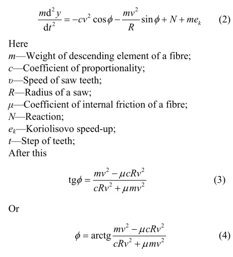
Defining the corner, at which the fibre is held on saw teeth, by ψ, we can write following formula:
(1)
where —a front corner of a tooth —corner between a radial surface of a saw and surface of shift of a fibre.
For defining the corner, an equation is developed on the movement of the element of fibre, descending from a tooth of a saw, in relation to mobile axes OXY:
2 2
2 2
d
cos sin
d k
m y mv
cv N me
R
t (2)
Here
m—Weight of descending element of a fibre; c—Coefficient of proportionality;
υ—Speed of saw teeth; R—Radius of a saw;
μ—Coefficient of internal friction of a fibre; N—Reaction;
ek—Koriolisovo speed-up; t—Step of teeth;
After this
2 2
2
tg mv cRv
cRv mv
2 (3)
Or
2 2
2
arctgmv cRv cRv mv
2 (4)
2. Materials and Methods
This Table 1 shows the values of parameters in Figure 1 [3,4].
[image:1.595.310.541.388.642.2]A. S. MAMATOVICH ET AL. 123
Figure 1.Schematic diagram and parameters of saw teeth developed by G.I.Boldinskiy.
Table 1 for Figure 1.
φ h (mm) t (mm) β γ1 (S4) (mmΔABC1 2) ψ
20˚ 4 4 20˚ 17˚- 18˚ 3.1 20˚
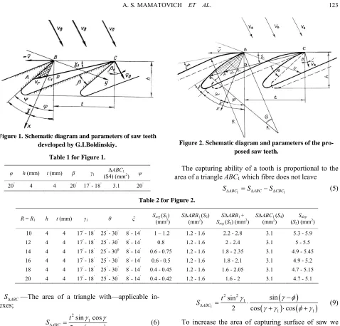
Figure 2.Schematic diagram and parameters of the
pro-The capturing ability of a tooth is proportional to the ar
1 (5)
Table 2 for Figure 2.
R = R1 h t (mm) γ1 θ ξ Sseg (S1) SΔABB1 (S2) SSΔABB1 + ) SΔABC1 (S4) (S Sdop
5 2)
posed saw teeth.
ea of a triangle ABC1 which fibre does not leave
SABC1 SABCSCBC
(mm2) (mm2)
seg (S3) (mm2 (mm2) ) (mm
10 4 4 17˚- 18˚ 25˚- 30˚ 8˚- 14˚ 1 – 1.2 1.2 - 1.6 2.2 - 2.8 3.1 5.3 - 5.9 12 4 4 17˚- 18˚ 25˚- 30˚ 8˚- 14˚ 0.8 1.2 - 1.6 2 - 2.4 3.1 5 - 5.5 14 4 4 17˚- 18˚ 25˚- 300 8˚- 14˚ 0.6 - 0.75 1.2 - 1.6 1.8 - 2.35 3.1 4.9 - 5.45 16 4 4 17˚- 18˚ 25˚- 30˚ 8˚- 14˚ 0.6 - 0.5 1.2 - 1.6 1.8 - 2.1 3.1 4.9 - 5.2 18 4 4 17˚- 18˚ 25˚- 30˚ 8˚- 14˚ 0.4 - 0.45 1.2 - 1.6 1.6 - 2.05 3.1 4.7 - 5.15 20 4 4 17˚- 18˚ 25˚- 30˚ 8˚- 14˚ 0.4 - 0.42 1.2 - 1.6 1.6 - 2 3.1 4.7 - 5.1
—The area of a triangle with—applicable
in-
ABC
S dexes;
2 1
1
sin cos 2 cos ABC
t
S
(6)
1 2
1 1
sin cos 2 cos CBC
t
S
(7)
Here
ner between vectors of relative speed and ta
γ1—Cor vr
ngent to a circle;
1 1
1
cos arctg
sin b
b
v v v
(8)
—Linear speed of cotton roll in its meeting point
b
v
with saw;
1
—Corner between the radius of a saw and vector of
lacing the received figures by formula (6) and (7) on
speed. By p
formula (5) we can find the area of capturing surface of saw teeth [1-3,5].
1 2
ABC
S
2 2
1
1 1
sin sin
cos cos
t
(9)
To increase the area of capturing surface of s offer a new changed profile of saw of saw cylinder. This w
tip will be about 25˚- 30˚.
rch ВВ;
t arc and str
s;
ich is kept in a
aw we
ork examines the influence of the changed form of tooth of saw cylinder on the area of fibre capturing sur-face (Figure 2).
The profile of a tooth resembles an arch, on which the corner of tooth’s
Vв—Speed of a particle of cotton roll at the moment of its meeting with saw tooth;
V—Linear speed of the end of a saw tooth; θ—The central corner of an a 1
ξ—Corner between a tangent carried ou aight line shoulder of teeth structure;
β1—Corner between the radius of saw and direction of
movement of light fibre approaching saw φ—Corner of friction of fibre on fibre; γ—Front corner of tooth.
tri an additional triangle АВВ1
an
angle AВС1, and also in
d a segment described by arch ВВ1. The area of the
triangle SABC1 is determined by well-known formula:
1
1 1
2 cos cos
C 2 2 1 sin sin AB t
S
)
As we see, fibre capturing ability of saw te
termined by the areas of triangles AВС1 and АВВ1, and
al
(10
eth is
de-so the segment ВВ1. Last two areas are additional to the
basic area of a triangle AВС1.
The area of a triangle АВВ1 is determined as follows:
1 ?
ABB
S
From a triangle ΔВВ1С under e theorem of sine we
can define СВ1:
th
1 1 cosCB
cos
t
then
1 1 2 1 1 1 cos sin 1 1 sin2 2 cos
BCB
S BC CB t
(11)
The additional area of a triangle АВВ1:
1 1
2
2 cos sin
ABB BCB ABC
1 1
1 1
sin cos
2 cos 2cos
S S S
t
t
2 1 1 1 1cos( ) cos cos cos sin
2 cos cos
t 1
(12)
Now we pass to definition of the area of a seg
ВВ1, chord which is determined der the formula:
1 ? BB ment un
1 1 sin cosBB t
(13)
The central corner of a segment arccosA
where:
2 2 2 2
1
2 2
1
sin 2 cos
2 cos t R A R
(14)
Then the area of a segment:
1
2 2 2
0 2π
360 seg
1 2 arccos 2 dop seg ABBR
S S S A
2
1 1
1
1 1
cos cos cos cos
sin
2 cos cos
t
(16) From the formula (16), it can be seen that the area Sdop
mainly depends on corners γ, γ1 and ξ.
At the appropriate selection of these corners, the op-timum additional area of fibre capture by saw teeth is achieved.
ssion
ndence of a corner ξ between a tangent of
re means anges θ = θ (ξ) at R = 20 cm. The yellow line on a
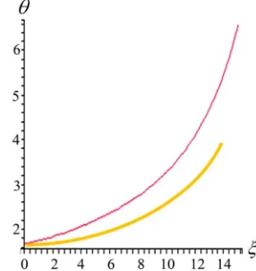
fig-3. Numerical Results and Discu
Figure 3 shows changes of the central corner θ arches ВВ1, in depe
the spent bow-shaped and direct back of a profile of teeths [6,7]. The red line on a schedule figu
ch
ure shows changes θ = θ (ξ) at R = 10 cm. We take cor-ner radius from the given schedule R =10 cm because at this value the tooth height will be equal h =4mm and a tooth step t = 4mm. At these data the most optimum value is θ = 25˚ - 30˚at ξ = 14˚. If we accept optimum
value θ = 25˚- 30˚and ξ = 14˚ and radius R = 20 cm that
leads to increase of a step and tooth heights. It leads to seed jamming in a backlash between teeth. As a result it will lead to intensive crash of seeds between tooth of a saw and a grid-iron saw gin. From this follows that the central corner θ arches ВВ1 should be in θ = 25˚- 30˚
lim-its and not exceed these values. Change of the additional area of a segment depending on a corner ξ pi various radiuses of curvature of a new profile of teeth. Optimum value of the area of a segment is Sseg = 0.01 cm2 which
corresponds R = 10 cm, ξ = 14˚.
In Figure 3 when the maximum value of ξeqauals to 14° and when the maximum value of θ equals to 30˚, the
level of teeth capturing fiber reaches its maximum
de-π π arccos
arccos 2
BB R R A R
S A (15)
Thus, the additional areas promoting the increase of
[image:3.595.56.291.277.491.2] [image:3.595.349.492.547.698.2]A. S. MAMATOVICH ET AL. 125
gree.
In Figure 4, the area of Sseg (S1) has been determined
at different radiuses according to the value of ξ.
In Figure 5, the area of (S2) triangle has been
found at different radiuses to the value of ξ. In Figure 6, in order to find S (S), we have added the area of Sseg (S1) to the area of (S2) triangle.
Since we know the area of S4) triangle, we
have added the area of S4 to the area of S3 and as a re-sult, we have determined the pturing fiber of new profiled teeth based on t ematic modeling and graphics (Figure 7). There are icron fibers in the area of Using the n profile, we can inc
4.
ent
1
ABB
S according
dop 3
1
ABB
S
SABC1 (
area of ca he math
100 m ew teeth
1
rease the amount of fiber. ABC
S .
Conclusions
Theoretical and the experim al researches executed at
Figure 4.Variance of the area Sseg(S1) versus corner ξ.
Figure 5. Variance of the area S△ABB1 (S2) versus corner ξ.
Figure 6. Variance of the area Sdop(S3) versus corner ξ.
Figure 7. Variance of the area of capturing fiber of the new
Tashkent Textile institute by B. A. Levkovich, N. G. Gulidov, G. I. Boldinskiy and G. I. Miroshnechenko and analytical formulas (10) for definition of the area of cap-ture of a fibre by saw tooth are offered. Values of area
calculated under the standard data of saw gin = 0.031 cm2 which contains 100 mkr
fi-sider a new profile of a tooth of saw gin it will increase the useful area of capture of pense of a bow-shaped profile of a tooth it e additional areas in the form of triangle gment Sseg. On Figure 3 optimal alues of
direct ξ = 14 are id . Within this data the profiled teeth (S5) versus corner ξ.
1
ABC
S equal bres. If offered fibre. At will ge
1
ABB
S
betwee ack of
1
ABC
S to con by us
the ex nerate th and se
n a t teeth
v
the central corner of an arch θ = 4˚ and value of a corner
angent of the spent bow-shaped and
˚ entified
b
areas of additional triangle SABB1 = 1.2 mm2 and seg-ment Sseg = 1 mm2 are calculated and as a result an
addi-tional area is received:
1 1
2
1.2 1 3.1 5.3 mm
dop ABB seg ABC
S S S S . The given figures in Table 2 show that the area of fi-bre capturing surface of saw tooth widened two times. The highest figure of the area of the surface is achieved at R = 10. Proportionally, at R = 20 the area of segment decreases and fibre capturing capacity also decreases.
e c
offered new design of a saw on cotton processing industry will increase the productiv of
. Azizov and A. I. Karimov, “Defining the Interac-tion of Cotton with Hilly Ginning Kolosnic,” Journal of
echanical Engineers, Vol. 3, 2005. ] G. I. Miroshnechenko, “Bases of Designing of Machines
shev and A. I. Karimov, “The Analysis of
Work-The values have been checked and prepared in Maple 9.5. Drawings have been prepared and projected through T-Flex CAD programm using th alculated values.
Stemming from these facts, it can be concluded that the application of the
ity of
ginnng, and also will bring to saving of power re-sources.
5. References
[1] S. M. Azizov and A. I. Karimov, “The Analysis of the Influence of the Clearance between Saw on Length Fila-ment,” Journal of the Problem Mechanical Engineers,
2004. [2] S. M
the Problem M
[3
Primary Processing of Cotton,” Moscow, 1972. [4] V. I. Roganov, et al., “Primary Processing of Cotton,”
Moscow, 1965. [5] J. Erga
ing Parts Cotton Gin,” Journal of the Problem Mechani-cal Engineers, Vol. 1, 2004.