N I M A NETWORK INTERFACE MACHINE
FOR DISTRIBUTED COMPUTER NETivORKS
by P.J. Chappell B Sc
A Thesis submitted in partial fulfilment of the requirements for the Degree of Master of Science in Computer Science
ABSTRACT
The Network Interface Machine (NIM) is a microprocessor-based interface used to connect diverse computers and terminals to a communications network. The purpose of using the NIM, as contrasted to direct connection, is to offload the network interface mechanisms completely f~om the user devices and the underlying data communication
facility. This offloading provides a portable, simplified, and easily implemented, network interface which is adaptable to computers, terminals and networks with diverse
characteristics.
This thesis defines the architecture, internal design and implementation approach of the NIM, and the high-level description language used to specify the characteristics of a particular NIM implementation. NIM software is produced from the high-level description by program-generation techniques.
The thesis surveys data communication concepts, network architectures and implementation techniques. The benefits of general-purpose local computer networks -are discussed, and the requirements that such networks must satisfy are identified. The NIM concept is proposed as an answer to these requirements. The architecture, protocols,
imple~entation and descripti6n language for the areas of network control, terminal virtualisation, and external access interfaces are described in detail.
ACKNOWLEDGEMENTS
I would like to express my sincere appreciation to those people who have helped me throughout the preparation of this thesis.
I wish to thank my supervisor, Dr M A MacLean, for his
guidance, and particularly for his comments and suggestions during the writing of this thesis.
I particularly wish to thank my employers, Sperry Univac, for their generous support over the entire project, and the management of the Wanganui Computer Centre for their· cooperation and leave of absence enabling the completion of this project. I would also like to thank my typist, Suzanne, for her helpful and thoroughly professional assistance.
ii.
My gratitude to my friends, Ross and Mary, for their loyal friendship during my years at Canterbury, and their motivation and selfless hospitality during the preparation of this
dissertation, will never be forgotten.
Finally, I would like to take this opportunity to thank my parents· for their consistent generosity and encouragement
CONTENTS 1. 2. 2.1 2.2 2.2.1 2.2.2
2. 2. 3
2.3 2.3.1 2.3.2 2.3.3 2.4 INTRODUCTION
BASIC NETWORK CONCEPTS AND EVOLUTION
DEFINITIONS
EVOLUTION OF TERMINAL ACCESS NETWORKS
Logical Structure
Physical Structure
Summary
MULTI-COMPUTER NETWORKS
Packet Communications Systems
Classification of Network Architecture
Effects on Network Architecture
SUMMARY
3.
3.1
COMPUTER NETWORK STRUCTURE AND IMPLEMENTATION
3 .1.1
3 .1. 2
3.2 3.2.1 3.2.2 3.2.3 3.2.4 3.3 3.3.1 3.3.2 3.3.3
DATA LINK CONTROL PROTOCOLS
Byte Control Protocols
Bit-Oriented Protocols
DEVELOPMENT OF NETWORK TECHNOLOGY
Computer Manufacturers
The Telecommunications Industry
Private (Local) Networks
Summary
LOCAL COMPUTER NETWORKS
CONTENTS continued ...•
3.4 NETWORK IMPLEMENTATION TECHNIQUES
3.4.1 Low Level (Configurative) Approach 3.4.2 High Level (Generative) Approach 3.4.3 Summary of Implementation Approaches
3.5 DIRECTIONS FOR DEVELOPMENT
4. THE NETWORK INTERFACE MACHINE: CONCEPTS AND DESIGN
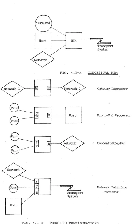
4.1 FUNCTIONAL REQUIREMENTS
4.1.1 Transport Services
4.1.2 Session Control
4.1~3 Terminal Interface Architecture
4.1.4 Host Interface Architecture
4.1.5 Network Interface Architecture
4.2 SOFTWARE ARCHITECTURE
4.2.1 Hierarchical Layers
4.3 HARDWARE ARCHITECTURE
4.3.1 Minicomputer Hardware
4.3.2 Multi-Microprocessor Hardware
4.4 IMPLEMENTATION APPROACHES
4.4.1 Design Objectives
4.4.2 Hardware
4.4.3 Possible Implementation Approaches 4.4.4 Chosen Implementation Approach
5.· SESSION CONTROL
5.1 ITEM DESCRIPTOR BASED PROTOCOLS
5.1.1 Item Descriptor Formats
5.1.2 Advantages and Disadvantages
CONTENTS continued •.• 5.2 5.~.1 5.2.2 5.3 5.3.1 5.3.2 5.3.3 5.4 5.4.1 5.4.2 5.5 5.5.1 5.5.2 5.5.3 5.5.4 6. 6.1 6 .1.1
6 .1. 2
6.2 6.2.1 6.2.2 6.2.3 6.2.4
SESSION CONTROL STRUCTURE Data Structures
Session Control Functions SESSION MANAGEMENT SERVICES Session Transport Protocol Transport Network Interface Session Control Protocol LOGICAL PORT SERVICES
Port Flow Control Protocol Logical Port.Multiplexor CONFIGURATION SPECIFICATION
Syntax Structure
Logical Node Configuration Physical Node Configuration Global Network Configuration
DATA PRESENTATION SERVICES DEVICE HARDWARE DEPENDENCIES
Transmission Interface Device Functions
PROGRAM INTERFACE Display Format Character Set
Device Capabilities Control Sequences
CONTENTS continued •••
6.3 USER FACILITIES 6.3.1 Input Facilities 6.3.2 Output Facilities 6.3.3 Process Control
6.4 VIRTUAL TERMINAL MODELS 6.4.1 Virtual Terminal Concepts 6.4.2 Virtual Terminal Profiles
6.4.3 Virtual Terminal Implementation 6.5 DATA PRESENTATION PROTOCOL
6.5.1 DPP .Functions 6.5.2 DPP Encoding
6.6 TERMINAL ATTRIBUTE SPECIFICATION 6.6.1 Universal Device Attributes 6.6.2 Device-specific Attributes
7. EXTERNAL INTERFACES
7.1 REQUIREMENTS AND OBJECTIVES 7.1.1 Functional Requirements 7.1.2 Structural Objectives 7.2 LINE MODULES
7.2.1 Line Interface Hardware 7.2.2 Input Processing Functions 7.2.3 Input Protocol Tables
7.2.4 Input Character Handling 7.2.5 Output Processing
7.2.6 Line Module Interface
CONTENTS continued •••
Page
7.3 LINE PROCESSES 190
7.3.1 Queue Control 191
7.3.2 Process Control 194
7. 3. 3 Input-Output Interfaces 196
7.4 PROTOCOL SPECIFICATION 196
7.4.1 Physical Line Attributes 197
7.4.2 Message Format Specifications 199
7.4.3 Protocol Procedure Specification 202
8. IMPLEMENTATION AND CONCLUSIONS 209
8.1 COMPILER STRUCTURE 209
8.1.1 Network Specification Analyser 209
8 .1. 2 Node Code Generator 210
8 .1. 3 Loader and Dump Utilities 210
8.2 IMPLEMENTATION STATUS 211
8.3 CONCLUSION 211
CONTENTS 2.1 3.1 3.2 3.3 3.4 3.5 3.6 3.7 4.1 4.2 5.1 5.2 5.3 5.4 5.5 5.6 6.1 6.2 6.3 FIGURES
SESSION ESTABLISHMENT
ISO REFERENCE MODEL CCITT TERMINOLOGY
SAMPLE X.25 PACKET FORMATS CNET CONTROLLER STRUCTURE MININET STATION STRUCTURE CONFIGURATION EXAMPLE NDL EXAMPLE
CONCEPTUAL NIM STRUCTURE
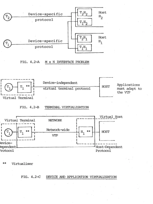
TERMINAL VIRTUALISATION MODELS
ITEM DESCRIPTOR FORMATS SESSION CONTROL TABLES STP HEADER FORMATS PFC HEADER FORMATS
CONFIGURATION STATEMENT SYNTAX
EXAMPLE CONFIGURATION SPECIFICATION
TERMINAL CONTROL SEQUENCES DPP ENCODING
TERMINAL ATTRIBUTE SPECIFICATION
CONTENTS
7.1-A 7.1-B 7.2 7.3 7.4 7.5 7.6 7.7-A 7.7-B 7.8 7.9 7.10 7.11
FIGURES continued .••
BIT-STUFFING ALGORITHM
BITSTUFFING ON THE 8080 MICROPROCESSOR STATE TRANSITIONS
CCT ENTRY CMM FLAGS
INTERRUPT PROCESSING ALGORITHM BUFFER CONTROL WORDS
LINE MODULE INTERFACE LINE MODULE COMMANDS MESSAGE QUEUE STRUCTURE
MESSAGE FOR~AT SPECIFICATION PROTOCOL PROCESS SYNTAX
PROTOCOL PROCESS STATEMENTS
1. INTRODUCTION
The current emphasis on distributed computer networks is but the latest phase in an evolutionary trend to bring computer access directly to the user. This trend began with the connection ,of a teleprinter directly to the computer and rudimentary software to allow a single user to interact directly with a running program. From this, time-sharing systems were developed which provided
concurrent access to many users while efficiently utilising the computer resources.
As the use o£ terminal access networks increased, an
awareness developed of the advantages of allowing computers to communicate not only with terminals, but also with other computers. Although at first each computer appeared to the other simply as a terminal, this started a trend towards the distribution of computational power away from a central
monolithic complex.
It is not difficult to provide access to a group of
compatible machines. In the simplest case, a terminal can be switched between individual physical circuits to each machine. An inter-machine link enables the convenient transfer of programs and data via utility programs, rather than the enforced use of physical media such as magnetic
h. H, d . .
tape. More sop 1scate software can prov1de general1sed 1\
remote access and the possibility of workload and resource sharing. Some manufacturers already provide, and most are developing, such facilities.
It is much more difficult to establish communication between different computers, even without considering any degree of cooperation. Effective communication requires a generalised data transport network which operates independently of any particular connected computer, and provides an easily
adapted interface to all types of computers and terminals. The concept is not new; i t had its birth in the ARPANET which connects diverse host machines in educational and research establishments throughout the United States, and has been in operation for over a decade. However, the unavailability of suitable 'off the shelf' hardware and software to interconnect diverse systems, and the high cost of custom development, has prohibited the implementation of all but a few experimental networks.
As communications technology continues to evolve, new transmission methods and protocols will be utilised, but the functionality of the network will, to a great extent, be determined by the design of the network interface. The network interface capabilities and the methods of their implementation primarily determine the 'personality' of the network - they affect the ease of use, transparency,
vendor independence, cost and flexibility of the network.
The network should aim to provide a 'friendly' interface, so that the attached devices may be unified into a complete system with minimised impact on each device. If the
network interface is isolated as much as possible from the user devices and the underlying data transport services, the network will have the required versatility and
capabilities to provide transparent interconnections for a. wide range of devices and data tran~port architectures.
The microprocessor based communications processor has the potential to become an 'off the shelf' building block for distributed communications networks, in the same manner as modems and multiplexors are for terminal access ne~works today. However, before this potential can be realised, communications processor software systems must be developed possessing the attributes of modularity, adaptability,
transparency and portability.
Modularity refers to the ability to configure a
communications processor tailored to a particular physical environment by implementing functions using differing
hardware/software techniques to provide the appropriate performance level at minimum cost.
3.
Adaptability refers to the ability to change the logical
functions of the communications processor to support different line protocols and terminal types.
Transparency implies that a communications network connection between two end-points should be
indistinguishable from a physical link. In particula~, the network itself must establish and maintain logical connections internally, and must adapt its interface to the external devices.
Portability implies that the process of transferring the communications software generation system between computers must be substantially less expensive than its initial
This thesis investigates the design and implementation of a Network Interface Machine (NIM) which possesses the
abovementioned attributes. The NIM implements a generalised interface between diverse terminals and computers, and a data transport facility. The interface functions are specified by a high-level language description of the
terminal and communications link attributes, which directs a specially-developed 'program generator' or compiler to generate a customised communications processor operating system.
The following chapters examine the development and
characteristics of present communications sytems, resulting in a set of design requirements for the Network Interface Machine. An overall architectural framework is developed, leading to a detailed description of the architecture, protocols, implementation and description language for the network control, terminal virtualisation, and external access interface components.
2. BASIC NETWORK CONCEPTS AND EVOLUTION
Data communications systems have gradually evolved to
provide increasing remote accessibility to computer systems utilising both improved hardware technology and more
5.
efficient data transmission techniques. This chapter traces the architectural evolution of terminal access networks in terms of their physical configuration and logical structure, and .their expansion to multi-domain and distributed networks. This leads to the concept of an independent data transportation network providing a generalised communication facility between a set of terminal nodes which have peer, rather than
hierarchical, relationships with each other.
2.1 DEFINITIONS
The following basic concepts are defined here, and used throughout.
A ProtoaoZ refers to the agreements between two parties involved-in the interchange of information :r;elating to the format and meaning of control messages, and the sequence in which they are to be exchanged between the parties.
A Node is a physical entity within the network which may be addressed by a unique identifier. Its name is derived from graph theory where nodes are junction points formed by
connecting lines.
A Station is the logical point of attachment between a
terminal or computer and the network.
A Te~minaZ consists of one or more input/output devices (keyboard, display, printer etc.). Each device provides control functions which determine the formatting of the data, in addition to the basic input and output functions.
A Deviae Cont~oz P~otoaoZ refers to the set of command formats th~t are tiansmitted to a device to initiate particular control functions.
A Data Link Cont~oz P~otoaoZ is a protocol which manages the operation of a data link between nodes. It regulates the initiation, checking/ and, if necessary, retransmission of each message to ensure efficient and reliable data
transmission. Two well known examples are BISYNC (BSC) and HDLC.
An End-To-End Cont~oz P~otoaoZ is a protocol which controls the overall transfer of information between the source and destination nodes. It ensures overall data integrity, controls the rate of data flow, and_may provide for the segmentation of user messages into network data units
(messages of a fixed maximum size) commonly known as packets.
An A~ahiteatu~e refers to the overall struct~re of the communications system. It defines the logical structures
6 •
2.2 EVOLUTION OF TERMINAL ACCESS NETWORKS
This section traces the evolution of terminal access networks into a layered software and hardware hierarchy, and the
techniques developed to achieve the efficient utilisation of transmission facilities.
2.2.1 Logical Structures
7.
In the earliest systems providing remote access communications, responsibility for the management of the communication link and the external device lay solely within the province of the applications program. This resulted in a multiplicity of incompatible data link control protocols, device control
protocols and end-to-end protocols. Often these were considered as a single problem. Because of the diversity i t was
impossible to handle all link control functions within a single communications program; rather they were embedded within each user program, together with device control functions which formatted data and interpreted control characters in a unique manner for each device. Since a user program was intimately concerned with the characteristics of particular devices, any change i~ the device or data link protocol required
corresponding changes in each program. This also had the effect of restricting the use of lines and terminals to only those programs which implemented the data link and device control protocols for those particular devices. The use of
a singl·e line for different types of terminals or even
different applications was generally impossible because the devices and user programs themselves determined the
characteristics of the link.
associated with line management. These provided the
user with an interface to operating system functions which performed basic communications operations. An example of such a system is IBM's BTAM, which provided basic I/O operations on the line although the user was still
responsible for the higher level functions of line management such as polling.
Later developments such as TCAM (2.1) provided a logical connection between the applications program and the terminal via a set of message queues, and a central message control program which performed the line-related input and output operations.
TCAM also provided a degree of independence between the program, which was regarded as a producer and consumer of messages, and the terminal itself by providing 'hooks' in the message control program where specific routines could be invoked to provide translations from device-dependent to device-independent formats. User programs could be written in a manner largely independent of data link and device control protocols, providing a general interface between terminals and applications.
-VTAM (2.2) further enhanced general communicability between applications and terminals with the concept of a 'session' - a logical connection between two network-addressable units., referred to by symbolic names. Communications system
routines mapped these identifiers onto physical device addresses, established the communications link, and added the necessary headers to each message to route i t to its destination.
The above discussion has traced the development of
communications software from its initial concern of merely providing an interface to the communications hardware to a
9 .
system which provides a logical connection between producers and consumers of information. The separation of different functions into distinct software modules within a
hierarchical structure was a major factor in this development.
2.2.2 Physical Structure
The development of a functionally layered approach to
communications software had a parallel in the development of hardware systems to provide increased performance and
reliability of transmission-related functions.
The very nature of line control functions may require very frequent interruption of a processor when i t is performing relatively simple tasks such as message assembly and polling. In some cases the overhead incurred in saving and restoring the processor environment status during interrupt processing may be of the same order as the ~seful work within the
interrupt routine itself. Furthermore, the maximum latency time allowable in servicing the interrupt may typically be the assembly time of one character. Because of these
requirements the first step towards distribution of hardware functions was to move the message assembly functions to a separate_unit attached to the main processor. The increased capacity of this 'front-end processor' (FEP) enabled co~plete
delegation of line management functions, and also motivated the development of more sophisticated data-link protocols to initiate, control, check and terminate data transfer over the link.
Techniques were also developed to improve the utilisation of communications lines by sharing a single line between many terminals, and to allow the efficient use of more
cost-effective wide bandwidth lines. The primary techniques are:
• Multiplexed operation
• Concentration
2.2.2.1 Multi-Point (Polled) Operation
In this method (sometimes called multi-drop) a line is shared sequentially between many stations on the line so that each station has full usage of the line for a limited time frame, normally one message. One station on the line, referred to as the primary, allocates the line to each
10.
station in turn by requesting input (known as a poll) , or sending output. The data link control protocol includes a
station address field in the message formats, and each secondary responds only to those m~ssages addressed to it.
Multi-point operation provides an effective way of sharing a line between many similar terminals designed for the same data link protocol, particularly where the line capacity is several times greater than that required by a single terminal alone. It has the advantage that data is transferred to a station at the full line rate. However input operations incur some delay because the terminal must be polled before the data can be fransmitted. Since there is no guaranteed allocation to each station, a busy terminal could lock out other terminals from accessing the line. The actual response time will be a probabilistic function of the line speed, message size,
message rate per terminal and the number of terminals on the line, as well as the round-trip propagation delay for poll commands which may be particularly significant on half-duplex links. Various methods, generally based on some type of
An alternative to the explicit allocation of transmission resources by polling is known as contention mode. This was first used in the Aloha Net (2.3) - A network based on the use of terrestial or satellite radio communications rather than fixed lines. In contention mode no attempt is made to coordinate the use of the transmission medium, but each station simply transmits data as i t becomes available. This results in the possibility of a 'collision' in which two (or more) transmissions interfere with each other. When this occurs, the receiver will discard the complete message and each sender will retransmit the unacknowledged message after waiting for a random period. This method provides improved
response time when the actual traffic rate is low in relation to the total channel capacity. The channel becomes saturated at 18% of its theoretical capacity - if all messages are of the same size and are synchronised to a common clock the saturation point is increased to 36% of channel capacity. More recently, this technique has been used in many 'local networks' with a high-speed coaxial cable rather than radio transmission.
2.2.2.2 Multiplexing
Multiple~ing (together with the inverse operation of demultiplexing) refers to the combination of a number of communications channels onto one single channel of greater capacity. Each sub-channel is assigned some portion of the shared channel on a fixed predetermined basis. This
apportionment may be achieved by two methods:
• Frequency-Division Multiplexing
FDM splits the wide-band channel into a set of mutually exclusive subchannels of narrower bandwidth, each
occupying a. disjoint frequency range.
e Time-Division Multiplexing
TDM allocates the entire channel capacity to each subchannel during a fixed time slot within a cyclic. sequence.
Practical realisations of the time division technique can achieve more effective utilisation of the channel capacity. However some modems use FDM techniques to implement a low capacity 'back channel' to provide a limited simultaneous bidirectional .link for control information. This allows a link which would otherwise be restricted to half-duplex
(two way alternate) operation to avoid some of the
inefficiencies introduced by line turn-round delays and operate at a higher aggregate data rate.
2.2.2.3 Asynchronous Multiplexing
In most cases a remote terminal will be actively transmitting or receiving data only a few percent of the time i t is being used. A human operator typically interacts with a computer in a cycle of entering some request, waiting while i t is processed, receiving the response, and thinking before
repeating the cycle. Therefore in any syst~m with a static allocation of transmission facilities (such as synchronous multiplexing) the channel is still inefficiently used.
12.
Asynchronous Time Division Multiplexing (ATDM) or 'statistical multiplexing' is one technique which has been developed to overcome the inherent inefficiency of static channel
data unit (normally one character) is preceded by an address specifying the sub-channel to which i t belongs, and any sub-channel has the opportunity of using the next available time slot on the link rather than being restricted to a particular place in the overall sequence.
2.2.2.4 Concentration
The techniques examined so far fall into two categories.
Polling sequentially allocates the total capacity of the line to a station for the complete duration of a message through the handshaking implemented within the data link protocol. The actual data transfer utilises the full capacity of the transmission link, and ailocation overhead is incurred only once per message. The data link protocol provides some degree of message integrity checking, but requires each station to implement the data link control protocol and provide local message buffering. The input polling may introduce considerable overheads.
13.
Multiplexing provides quasi-parallel operation for each sub-channel by mapping several lower capacity sub-channels onto one-higher capacity physical link in s~ch a way that each sub-channel appears indistinguishable from a dedicated link. Because multiplexing affects only the physical link between end-points i t is transparent and has no effect on the higher levels of the communications system. Multiplexing does
involve some inefficiency due either to the static sub-channel allocation resulting in unused time slots or. to the address information which must be attached to each character
transmitted.
disadvantages of either, although this requires a much higher degree of intelligence in the line sharing unit
(concentrator).
Because many stations may transmit at the same time the concentrator must provide buffering of input until time becomes available on the line to transmit it. Likewi.se data may arrive at a greater rate than the receiving
station can accept it, so further buffering may be required. In practice some limit must be placed on the size of
transmitted messages together with some form of pacirig or flow control to prevent saturation of the conentrator by any one station. The amount of buffering and the complexity of buffer management may vary considerably depending on the diversity of terminal types, line speeds and message lengths.
Concentration enables much fuller utilisation of the
communication link capacity to be obtained since buffering has a smoothing influence on traffic flow, providing a degree of isolation between the traffic on the communications line and each individual station. The use of intelligent
communications controllers at both ends of the line also enables the use of more sophisticated communications protocors.
2.2.3 Summary
Terminal access networks have evolved in two distinct areas; device independence and line control procedures.
A considerable degree of device independence and data link protocol independence was achieved by inserting intermediary data formatting levels (known as presentation services)
14.
with the nature of the line protocol or details of the device control codes for particular terminals.
Likewise with the advent of intelligent concentrators the management and sharing of communications line resources became a separate function from the particular device using the communications facility. This led to the development of standardised data link cqntrol protocols implemented by a wide range of devices.
However the onus for adapting to the characteristics of
any particular device remained with the user of that device -hence if one device could be accessed from many systems then each system would be required to implement data formatting services for that device' rather than the device itself adapting to some common standard.
2.3 MULTI-COMPUTER NETWORKS
The preceding discussion of terminal access networks covered what are commonly known as 'star' networks involving the connecti0n of many remote terminals to a single central
computer complex. As functions were distributed to different parts of the network, the basic star structure evolved into more complex hierarchical structures, but the one-to-one relationship between terminals and hosts remained.
' When multi-computer networks are considered, such a simple
\
relationship between terminals and hosts no longer applies. A terminal may wish to communicate with one host, or
alternately with many hosts; hosts may wish to communicate with other hosts or terminals may wish to communicate with other terminals. In fact the distinction between hosts and terminals may largely disappear, with both being regarded
simply as end users of the communications system.
2. 3.1 Packet Communications Sys~~~~
The efficient utilisation of the transmission link capacity has been a major consideration in the development of the various line sharing methods. The most efficient technique developed, concentration, is characterised by two key
attributes:
e Data is buffered within the concentrator, which has a smoothing effect on the data flow, allowing a higher average throughput on a line of given capacity.
• Terminal multiplexing or polling is performed locally by the concentrator. The data link protocol between
the host and the concentrator may be designed to maximise the utilisation of the link capacity.
Packet switching is an extended form of concentration, just as concentration itself is an extended form of ATOM.
Concentration multiplexes messages between end points which are physl~ally connected by a single communications link. In the process of packet switching however, the source and
destination first agree to a logical connection. The logical connection between source and destination may be implemented by more than one physical circuit, in parallel or in series.
Messages may be segmented (if necessary) into smaller portions of some fixed maximum size and each segment transmitted individually across the network to the
destination, where they will be reassembled back into a complete message.
At each intermediate point routing tables determine the
next link in the journey to the destination, and when dynamic routing algorithms are employed successive segements may take different routes across the network and even arrive out of sequence.
Because message flow can be controlled between the source and the destination, and the network data units are fixed in size, buffering and queue management within the network can be simplified. This minimises transportation delays within the network and results in a high rate of data throughput.
Packet oriented communications networks are the preferred technique for future communications systems, because
• Packet networks provide high throughput and fast response times due to the efficient utilisation and sharing of the communications facilities.
• Packet networks provide a general communicability since a transparent logical connection can be established between any two termination points of the-network independently of the actual_physical paths involved.
In addition, international standards have been developed from the outset which define packet interfaces to Public Data Networks (PONs), providing the facility of national and even global data communications in a similar manner to the voice telephone networks of the present day.
2.3.2 Classification of Network Architecture
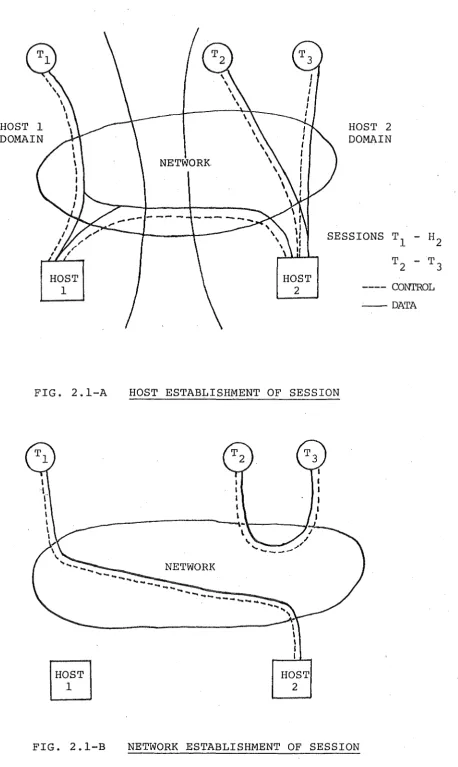
Since in a multi-computer network the logical connection between end users may be established dynamically (rather than statically as determined by the physical hierarchy) , a resource manager must be provided to initiate and terminate logical connections. Based on the distribution of this
resource management function, two classes of configurations may be defined:
2.3.3
Host establishment of session (Fig. 2.1-A).
If a terminal is associated with a local network of a 'parent host' the establishment of a logical
connection with another host requires the parent host to arrange the connection. Once this is done traffic may either pass through the parent on its way to the destination, or pass directly from the origin to the destination. Two terminals wishing to communicate can only do so through a common host.
Network establishment of session (Fig. 2.1-B).
If-both terminals and hosts are regarded simply as
-addressable units on the network the establishment of a logical connection between a terminal and a host or another terminal is purely an internal
network function~ Within the network terminals will most likely be associated with the local network of a network nodal processor, but this is transparent from the user viewpoint.
Effects on Network Architecture
The parent host' approach is typified by the Systems Network Architecture (SNA) of IBM (2.4). The SNA software was
HOST 1 DOMAIN
HOST
1
FIG. 2.1-A
FIG. 2.1-B
NETWORK
HOST 2
HOST 2
DOMAIN
19.
SESSIONS T
1 - H2 T2 - T3 ---- CONTROL --DATA
HOST ESTABLISHMENT OF SESSION
NETWORK
HOST 2
[image:29.598.91.550.42.809.2]initially developed to unite the communications components of existing communications access methods (eg. TCAM and VTAM) and applications subsystems (eg. IMS, CICS and JES) under a single umbrella in order to provide a migration path towards an integrated communications architecture. SNA was implemented to run on the same SYSTEM/370 3705 communications controller as the earlier software, thus being heavily dependent on the host SYSTEM/370 for network control functions. More recent developments have enabled couplingofSNA networks running on multiple hosts and the connection of smaller machines, but the orientation towards a dominant 'host' controlling the network remains.
SPERRY UNIVAC's Distributed Communications Architecture (DCA) (2.5) provides a contrast in that network operation is autonomous of any host computer that may be, connected. All devices connected to the network are co-equal in the
sense that each is regarded simply as a producer and consumer of messages. The lower Transport Network (TN) level provides a data transmission facility between any pair of network
ports, while the higher Communications System User (CSU) level provides a network interface of the appropriate functionality for the particular device.
2.4 SUMMARY
The one attribute which characterises the development of communications systems must surely be diversity. Diversity
20.
requirements of users rather than as a stage of a planned
development.
The examples considered here have been mainly from
large-system data communications networks.
They remain valid when
considering the interconnection of smaller systems, since it
should be possible both to avoid known shortcomings of
earlier approaches, and to determine from the outset those
areas requiring particular attention.
3. COMPUTER NETWORK STRUCTURE AND IMPLEMENTATION
This chapter surveys the current development of computer networks. After an initial introduction to data link protocols, the major paths of development are discussed, with particular emphasis on local computer networks. Finally two alternative approaches to the implementation of network software are examined.
3.1 DATA LINK CONTROL PROTOCOLS
A data link control protocol has three essential functions, being:
• Framing
The process of recognising the start and end bit sequences which delimit messages. These may not only bracket the actual information transmitted, but also indicate portions of the message to which the~checking mechanism applies.
• Link Management
The process of controlling transmission and reception on the link~ This may include the direction of
traffic on a half-duplex link, the particular station which may use the link, identification
(addressing) of receiver and sender, and link set-up. Possible link configurations may include point to point (dedicated link between two stations), multi-point (polled operation) and switched line (dial-in/ dial-out) •
e
Data Transfer and Message Integrity
The process of transferring data sequentially and without error over the link. This may include
regulating the rate of data transfer (flow control). Errors may be detected by parity checks (vertical and horizontal) or cyclic redundancy codes, or by message sequence numbers. Flow control and recovery may be implemented by two basic methods:
A
'Stop-Start'
method in which each messagerequires an explicit acknowledgement and go-ahead resporise before the next message is transmitted.
A
'Continuous ModuZo N'
method in which framesare sequence-numbered and may be transmitted continuously until a 'credit limit' on the number of outstanding unacknowledged messages is reached, when a response is specifically requested.
A highly desirable attribute is:
Transparency
It is often necessary to transfer binary data which may contain arbitrary bit patterns rather than
characters from some restricted set. Most protocols provide some mechanism for the transfer of such data while maintaining the ability to distinguish control information from data.
The communications protocols in common use may be
divided into two basic categories; byte control protocols (BCP's) and the more recently developed bit-oriented
protocols (BOP's). BSC (BISYNC) and the SDLC/HDLC-based family are the most well-known examples of each type respectively, while DDCMP has characteristics of both. In all cases the basic components of a message are the header of control information, user data, and error-detection codes.
3.1.1 Byte Control Protocols
In byte control protocols, characters from a reserved subset of the character set (known as control characters) are ~sed to frame the message, delimit message components, and perform link management functions.
2 4.
In BISYNC the start of the variable length header is indicated by the SOH (Start of Header) character. The header is
terminated and the start of the data portion of the message is indicated by the STX (Start of Text) character. The data may be termined by an ETX (End of Text) character, or an ETB
(End of Text Block) when the message has been segmented and more blocks are to follow.
The problem of control characters in the user data being
interpreted incorrectly is overcome by a special feature
known as
transparent mode.
If the text is to be sent intransparent mode, i t is bracketed by DLE STX and DLE ETX
(or DLE ETB) • The DLE indicates that the following text
may contain embedded control characters. If a DLE character
appears in the text, a second DLE is inserted by the sending
' ' '
station. In turn, the receiving station discards one DLE
of each consecutive pair. This process is known as
byte-stuffing.
The DDCMP protocol uses a frame structure for all data
messages. Each message begins with one control character to
distinguish between data, control and bootstrap frames. The
header contains a count field specifying the length of the
data, as well as sequence and acknowledgement information.
The use of a count in this manner achieves data transparency
without the use of byte-stuffing. Routing and addressing
functions are performed by a separate Network Services
Protocol (NSP) format header preceding the data frame.
3.1.2 Bit-Oriented Protocols
An alternative to using a reserved control ~haracter set, with the inherent problem of these characters appearing in
the data, is to rely on
positionaZ significance
within astructured control field. A structure is positionally
significant when the semantics of fields within i t are
defined by the relative bit positions, rather than character
content.
The HDLC/ADCCP protocol (standardised by ISO and ANSI
respectively), together with variations implemented by the
various computer manufacturers, form the family of
bit-oriented protocols. They have two distinguishing
characteristics, the frame format and the transparency technique.
There is a single frame format (or communications envelope) for all message types and link configurations; in comparison to the numerous message formats used by the byte-oriented protocols. The frame is delimited at the beginning and end by a special binary sequence, 01111110, which is called the
flag.
The header follows the initial flag, consisting of an8-bit address field, and an 8-bit control field which may be interpreted in three formats depending on the setting of the first two bits. The 16-bit cyclic redundancy code, which immediately precedes the trailing flag, checks the entire frame.
Transparency is achieved by the technique of zero insertion and deletion, more commonly known as
bit-stuffing.
After transmitting the initial flag, the sending station monitors the output bit by bit, rather than character by character as in byte-oriented protocols. Any time a string of five ones occurs, the sending station will automatically insert an26.
extra zero into the transmitted stream to avoid the possibility of a flag sequence being transmitted unintentionally.
The receiving station monitors the incoming bit-stream.
When five consecutive ones are detected, the following bit is examined. If i t is a zero, the bit has been 'stuffed' by the transmitter and i t is discarded, rather than being included in the message being assembled. If the sixth bit is a one, the sequence may be a flag (the next bit being 0) or one of two additional control sequences. These are the
go-ahead
(7 ones) used in loop configurations, and the
aboPt
(8 to 15 ones) used to abort a partially transmitted frame. Since27.
3.2 DEVELOPMENT OF NETWORK TECHNOLOGY
Communications network technology has evolved along three
paths, oriented towards the particular applications requirements of the developers; the computer manufacturers, the
telecommunications industry, and private or academic institutions.
3.2.1 Computer Manufacturers
Among the computer manufacturers, DECNET (3.1), SNA (3.2)
and TELCON (DCA) (3.3) are the most mature products available. They are characterised by the provision of higher level
services tailored towards the particular applications
environment. SNA and TELCON, oriented towards the commercial data-processing environment, provide 'presentation services' which perform mappings from a network-wide device-independent
(virtual terminal) protocol to the particular device control protocol for a variety of terminals. DECNET is designed for the interconnection of minicomputers, which may be running under different operating systems. With an orientation towards distributed and real-time processing, i t provides a File Transfer Protocol (FTP) to facilitate the
cross-generation of software and remote file access between machines.
3.2.2 The Telecommunications Industry
The telecommunications industry has traditionally provided analogue (voice) communications between subscribers connected via local exchanges and the toll trunk network. The rapid development of electronic technology and the emergence of distributed data processing systems has resulted in a growing need for digital data transmission facilities. While the
and forseeable data traffic volume, the introduction of new technology provides an opportunity to establish from the outset common interfaces that will allow the direct
interconnection of public qata networks on a global basis.
The trend towards standardisation has taken two directions. The international standards organisation, ISO, has developed a common reference model defining terminology and functions to facilitate the analysis and interconnection of different networks. The international telecommunications union, the CCITT, has developed the X.25 Recommendation to provide a standard interface to public packet-switching data networks.
3.2.2.1 Open Systems Interconnection
Open Systems Interconnection refers to the transparent
interconnection of different computer systems at all levels from the physical communication medium through to the
application system.
28.
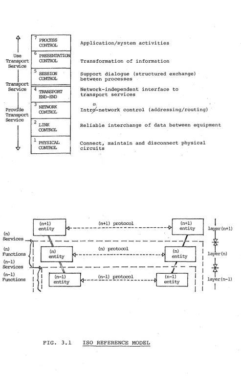
ISO has develope~ a reference model (3.4) for open systems
interconnection which defines the structure of a communications system in terms of a seven-layer model (Fig. 3.1). The
purpose of the model is to provide a complete reference
structure for communications systems, partitioned into layers of functionally contained components which are each easily comprehended. The model is intended to:
• Provide a common perspective from which to evaluate existing systems
• Identify those areas requiring further development and standardisation
i
Use Transport ServiceI
Transport Service Provide Transport Service1
7 P.R<X:ESS CONTROL
6 PRESENTATION
CONTROL
·s SESSION CONTROL
4 TAANSPORI'
END-END 3NElliORK CONTROL 2 LINK CONTROL
l PHYSICAL CONI'ROL
(n+l) entity
FIG. 3.1
Application/system activities
Transformation of information
Support dialogue (structured exchange) between processes
Network-independent interface to tiansport services
fYJ
Intryf-network control (addressing/routing)
29.
Reliable interchange of data between equipment
Connect, maintain and disconnect physical circuits
(n+l) protocol (n+l)
--- ---{;>
entityISO REFERENCE MODEL
[image:39.598.49.543.53.832.2]The layers comprising the model are:
• Process Control (Level 7)
Performs activities to support the information processing function of the application. Examples
are remote batch, file transfer, or. terminal
interaction protocols.
• Presentation Control (Level 6)
Provides the required transformations to information being transferred. Examples are encryption, data compression, and terminal virtualisation.
• Session Control (Level 5)
Supports a dialog (structured exchange) between users. This includes resolving symbolic user addresses, the establishment and termination of sessions, and the structured interchange of data between users. It uses the transport network to exchange messages between nodes.
Transport End-to-End Control (Level 4)
Provides the interface to the transport network, implementing end-to-end control and information exchange across simple or complex networks.
• Network Control (Level 3)
Provides the control functions of switching points for intra-network operation, such as addressing and routing.
o
Data Link
(Level 2)Provides the reliable interchange of data between equipments connected by Level 1 facilities.
o
PhysicaZ Link
(Level 1)Includes the physical, electrical, functional and procedural characteristics of the physical circuits between equipment)(.
3.2.2.2 The X.25 Public Data Network Interface
5'
31.
The development of the X.25 interface (3.fl) has been very
c;~)
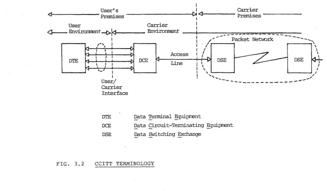
significant. A brief description follows, using theterminology of the telecommunications industry as illustrated in Fig. 3.2.
The Data Terminal Equipment (DTE) can be any type of user facility from a simple terminal to a large computer system. The Data Circuit-terminating Equipment (DCE) performs the interface function into the network proper, which is known as the Data Switching Exchange (DSE).
The CCITT has standardised the protocols across the DTE/DCE interface. This interface is considered at three levels. These are:
The Physical Level
J
User's I Carrier
<11---Premises
1 <1 Premises
-User Carrier ~
<Jt---
Environrrent-1.>}::1
Environrrent 1 _ _ _ _ _ _ _ __ _D'IE
FIG. 3.2
I
I /_,.-
Packet Network - - - -...I r 1 • 1 "
I
I
User/ Carrier Interface
Access
DCE
Line
.
\\ \ \
, _usE
~uSE.... ,
I \ I
I \ I
I L ' .._._ _, .I
.
- ,_.,
---~~~
D'IE !2_ata Tenninal ~prrent
DCE !2_ata Circuit-Tenninating ~prrent
DSE
Data Switching ~changeCCITT TERMINOLOGY
w
[image:42.846.61.735.163.556.2]e The
Link Aaaesa PPoaeduPe
(LAP)The bit-oriented LAP and LAP-B data link control
protocols provide a transparent bi-directional transfer of data blocks between a station in the DTE and a
station in the DCE. The earlier LAP implemented an independent link in each direction using the HDLC
Asynchronous Response Mode (ARM), while the more rece.nt (and preferred) LAP-B uses the full-duplex Asynchronous Balanced Mode (ABM) or HDLC.
e
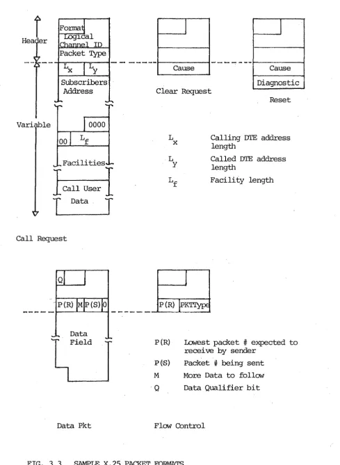
The Paaket Levet
The packet level defines a standard packet header and formats for the construction of data and control ·packets
(see Fig. 3.3), and procedures to establish, multiplex and control the flow of data over many virtual calls on the single physical link between the DTE and the DCE.
33.
It must be noted that.the X.25 Recommendation provides a mechanism only for the transparent transfer of data blocks between paired DTE's across a public data network. Since X.25 is an access method, i t may be related to different levels
of
the ISO model, depending on theW?Y
the X.25 link is used. If each terminal uses a unique X.25 call then the X.25 network performs the transport level functions directly. If, however, the number of virtual calls that can besupported is restricted then a separate transport level is required to perform end-to-end multiplexing of multiple terminals onto a single X.25 call at the network level. Higher level user-to-user protocols are beyond the scope of
the X.25 interface. The latest draft Recommendation (3.y)
~
has deleted references to protocol level numbers to avoidr
Hea er
Vari le
Subscribers Address
00
Facilities
I
Call UserI
T
DataJ
call Request
Q
Data Field
Data Pkt
J
J
Cause Cause
Diagnostic Clear Request
L
X
P(R)
P(S)
Reset
Calling DTE address length
Called DTE address length
Facility length
Lowest packet
#
expected to receive by senderPacket # being sent M More Data to follo:N Q Data Qualifier bit
Flo:N Control
FIG. 3.3 SAMPLE X.25 PACKET FORMATS
[image:44.598.59.549.101.771.2]Among networks currently using the X.25 interface are the American TELENET, the French TRANSPAC and the Canadian DATAPAC networks.
3.2.3 Private (Local) Networks
Most academic or research networks fall into the class of what are becoming known as Local Computer Networks (LCN's). A variety of definitions have been proposed for local
networking (3.7), but none has found general acceptance. In this discussion local networks will be characterised by the following attributes:
e Owned by and operating within a single organisation
e Short distances (under 10 km)
e High data rates
e Some form of mesh (packet switching) or broadcast (data bus) structure rather than the conventional star (hierarchical) network structure.
The usage of LCN's have evolved in two distinct applications:
e The-improvement of existing systems by the addition of 'frontend' communications systems or 'backend'
peripheral systems. The Ethernet (3.8) is possibly the most well-known example of a high-speed broadcast
packet communications network, while the HYPERCHANNEL (TM) (3.9) is a high-speed bus-oriented network designed to .facilitate backend communications between large mainframe
and peripheral systems.
35.
e The exploration of new systems concepts such as distributed processing. CM* (3.10) and C.MMP (3.10) are two
well-known distributed multi-processor systems utilising a
high-speed packet switch and an interprocessor bus network respectively.
The actual application of local network technology is limited. Many systems remain laboratory curiosities. At the time of writing, the HYPERCHANNEL (TM) is the only
system commercially available, but Xerox, Digital Equipment Corporation (DEC) and Intel are jointly developing a common Ethernet standard.
3.2.4 Summary
Communications network technology has developed in different directions in response to differing market needs.
The computer manufacturers have tailored their network
systems towards their particular market segments with a heavy emphasis on end-user facilities and the support and
integration of existing products within a new framework.
The telecommunications industry is primarily concerned with the control of access to public data networks.
The various local networks have been developed as pragmatic solutions to the requirements of particular organisations. Free from the restrictions o£ ancestral heritage and the need to function in an arbitrary user environment they often display a stark simpli,ci ty of design.
3.3 LOCAL COMPUTER NETWORKS
This section examines the structure of two local network
implementations. The particular two have been chosen because they demonstrate a wide variation of architecture while
meeting similar objectives; CNET uses broadcast transmission
of large (up to 256 byte) packets while MININET performs
store-and-forward switching of 16-bit data words.
3.3.1 CNET
37.
CNET was developed in the Computer Systems Laboratory, Queen
Mary College (University of London) . The network ~rchitecture
is described in (3.11) while (3.12) contains
implementation-level detail.
3.3.1.1 Evolution Context
CNET is an inexrensive ~acket communications network for the interconnection of many devices, which may vary in intelligence
from printers and terminals to computers. I t evolved from the
requirement for a flexible interconnection medium which would
be extensible, reasonably low cost, yet powerful, in order to
construct distributed systems as well as provide a conventional
node-to-node communications system. The design is heavily
influenced by Ethernet.
3.3.1.2 Data Transport Technology
Node controllers are connected via a common passive coaxial
cable referred to as the etheP. Packets consist of an 8-byte header, up to 256 bytes of user data and a 1-byte
checksum, with transparency being achieved by a data count
in the header. Packets are broadcast across the ether, and
each data packet is individually acknowledged.
A host device wishing to send a message passes the message
to its associated controller. The controller monitors the
transmission has completed. When the ether is clear, the controller immediately begins to transmit the queued
packet. This packet is received by every controller on the ether but ignored by all but the addressed destination.
If more than one controller attempts to transmit
simultaneously, a collision will occur resulting in packet corruption. Each transmitting controller performs
aoZZision
detection
by simultaneously receiving the data on the ether3 8.
as i t is transmitted. When a mismat~h is detected, indicating a collision or noise corruption, the sending controller
immediately ceases transmission and forces the ether into a 'break' state, which causes all receiving controllers to discard the packet. After a random timeout the controller will attempt to retransmit the packet.
The destination controller performs a parity check before passing the packet to its attached device and returning an acknowledgement to the source. A node may have only one packet outstanding to each other node, which must be
acknowledged before another packet can be sent to that node.
3.3.1.3 Node Structure
A minimal CNET controller consists of a Motorola M6800
microprocessor, a 10 msec real-time clock, 2K bytes program memory, 4K bytes buffer memory, an Asynchronous
Communications Interface Adaptor (ACIA) to the ether and
another ACIA or parallel port to the.device. The approximate cost of the hardware is $180.
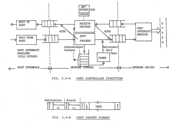
The structure of the controller software is summarised in Fig. 3.4-A and the packet format in Fig. 3.4-B. Data may be transferred simultaneously to and from the host under
~SOR
~
II
<r-f
~
_:_
}-ITifJ~ ~
IRECEIVE
PROCESS
<J--RECV FRa-1 HOST
HOST INTERRUPr HANDLERS
(FULL DUPLEX)
1 I 1 I I I I XMIT
I PROCESS t !----,....--"""'
Acknowledged Packets I I ~ 1 transmit!
Self : ....---"---, Test :
TIMER I I
1
t
HOST IN'IERFACE ~ NE'IWORK CONTROL
----~~
NE'IWORK DRIVERI
t
FIG. 3.4-A CNET CONTROLLER STRUCTURE
•
Destination
i
Source :Sf----.--,
I
~ IPr~~essl ~ IPr~~essl ~I ~
I
DlfA
I
§
I
FIG. 3.4-B CNET PACKET FOR~T
[image:49.843.89.742.62.572.2]Since reception and transmission are alternate rather than simultaneous, a single interrupt handler performs both operations. At the completion of receiving any
packet the interrupt handler will attempt to initiate any pending transmission. During transmission the actual data on the ether is monitored through the receiver interface to detect 'collisions' or other data corruption.
At the packet level independent transmit and receive
40.
processes monitor their respective input queues transferring data packets to th~ii output queues, generating and processing acknowledgement packets, and interpreting the network control packets which establish and terminate logical network
connections.
A timer driven from the real time clock performs collision resolutiontiming, transfers packets from the 'acknowledgement pending' queue to the transmit queue for retransmission when they time out, and periodically schedules self-test packets.
3.3.1.4 Network Interface
The physical interface between the controller and the device may be either an asynchronous character interface for
'
terminal-like devices, or a parallel port connecting to a minicomputer Direct Memory Access (DMA) controller.
Logically the controller appears as a 'door' between the host and the ether, simply transferring packets between
addressed nodes. A CNET controller could conceivably contain alternative interfaces implementing a virtual terminal
protocol or a 'gateway' transformer to another network
3.3.1.5 Connection Management
As indicated in Fig. 3.4-B packet addresses consist of two fields - an 8-bit node number and a 16-bit port or process identifier identifying the logical channel within the host. The controller administers a table of open inter-port
connections consisting of (source, destination) tuples, which is updated in response to control messages
originating from a network supervisor process residing in the host connected to the controller. The function of network supervision is thus split between the controller and the host.
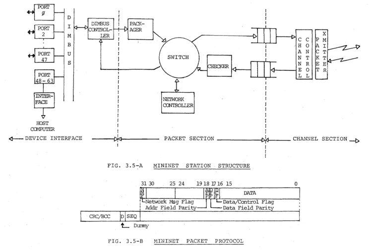
3.3.2 MINI NET
MININET is a joint development of the Polytechnic of Central London and the University of Bologna. Reference (3.13)
describes the packet protocol in detail, while (3.14) gives an overview of the network concepts and a description of the implementation.
3.3.2.1 Evolution Context
MININET-{s a packet switching data communications network developed to facilitate the interconnection of heterogeneous locally dispersed digital devices. These devices may not only be minicomputers and terminals, but also laboratory instrumentation which has a digital interface.
3.3.2.2 Data Transport Technology
Architecturally MININET consists of two types of nodes; the Stations which provide the external interface to the network and the Exchanges which implement a store-forward packet