Study on Experimental and Modeling of Rotary Roll
Dressing of Grinding Wheels
A. H. Azizii, S. M. Rezaeiii, A.R. Rahimi and H. Baseri
Received 17 September 2008; received in revised 30 September 2009;accepted 24 February 2010
i Corresponding Author,A. H. Azizi is a Ph.D. student in Mechanical Engineering, Amirkabir University of Technology, Tehran, Iran, (e-mail: [email protected]).
ii
S.M. Rezaei is with the Department of Mechanical Engineering, Amirkabir University of Technology, Tehran, Iran (e-mail: [email protected]).
ABSTRACT
Two of the important parameters in grinding operation are surface roughness of the workpiece and the amount of consumed energy. These parameters are strongly affected by the condition of grinding wheel surface which is dependent on the dressing parameters. Predicting the roughness of the grinding wheel surface after dressing with known dressing parameters can improve the grinding process. Researchers have presented several models of the grinding surface after dressing. In this article, these models are analyzed and an improved model along with computer simulation of grinding wheel surface is presented with regard to rotary dressing parameters. Finally, the model is verified with experimental results. The theoretical values reasonably compare with experimental results. On the basis of this model and experimental results the effect of different rotary roll dressing parameters on grinding wheel and workpiece surface roughness are discussed.
KEYWORDS
Rotary dressing, Dressing parameters, Roughness, Steady profile
1. INTRODUCTION
In grinding process, surface roughness and condition of part surface is strongly affected by grinding wheel surface. In fact, surface of the part is a reflection of the grinding wheel surface. Furthermore, if the grinding wheel surface condition is recognized, then the surface roughness of the part can be predicted [1]. One of the grinding wheel preparing processes is dressing. There are several dressing methods. Among them, rotary roll dressing is one of the most common ones. Rotary roll dresser is a rotary wheel with many diamond grits bounded on its surface. Dull grits of grinding wheel surface are removed in contact with the dresser and new sharp grits on the grinding wheel surface are appeared. Important dressing parameters in this method are: 1) feed of the dresser in radial direction of the grinding wheel and 2) speed ratio between rotary dresser and the grinding wheel. Any changes in these parameters will affect quality and roughness of the part surface [2], [3].
Various models of wheel topography produced by the interactions between dresser and grinding wheel have been presented. But there are a few models that are concentrated on the rotary dressing operation. Brinksmeier and Cinar [4] Characterized the dressing
process by determination of the collision number of the abrasive grits in rotary cup dressing. Pruzak et al. [5] described the effects and importance of measured disc dressing factors on grinding performance. Baseri et al. [6] developed a new mathematical model of the dressing of grinding wheels by a diamond disc dresser. This model predicted the dressing forces and provided a basis for further prediction of wheel topography and the grinding process [7], [8]. Among presented models Byzmec [9], Darnbrough [10] and Mindek [11] have only modeled the rotary roll dressing. Their models have some restrictions which will be studied in the following section. In this article it is attempted to develop a new mathematical model of roll dressing along with computer simulation of grinding wheel surface. The presented model predicts grinding wheel surface topography after dressing with rotary roll dresser. The analytical and simulated results are compared with experimental results and the effects of rotary roll dressing parameters on workpiece and grinding wheel surface is discussed.
2. ANALYTIC AND GEOMETRIC MODELING
1–The diamond grits on the surface of the rotary dresser have a semi-circle shape and are arranged on the dresser surface with equal distance from its center.
2– The rotary dresser is balanced.
3– Lateral and peripheral vibrations of dresser can be ignored.
4–The peripheral velocity of grinding wheel and rotary dresser are constant.
5 – The area over which the surface profile is created is much smaller than the grinding wheel diameter. It can be considered that the grinding wheel has an infinite diameter, allowing it to be considered flat in the small area of contact.
6 – Grinding wheel is made of an isotropic material and brittle fracture will not occur.
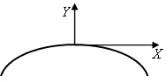
Fig. 1 illustrates the initial model presented by Byzmec and Darnbrough. When a diamond grit on dresser surface is engaged with grinding wheel surface as a homogenous solid a cusp is created. In order to identify dimensions of created cusp on the surface of the grinding wheel during
dressing the following equations are suggested: (1)
) ( 2 Sin t
D t V
X r
r
s + ω
=
(2) )]
( 1 [
2 Cos t
D
Y r
r ω
− =
where
V
s is peripheral velocity of the grinding wheel,r
D
is the diameter of rotary dresser,ω
r is the angular velocity of rotary dresser, andt
is the time needed to create one cusp on the grinding wheel surface.X
andY
are the dimensions of a cusp in the peripheral and radial direction of grinding wheel surface. The coordinate axes are attached to the grinding wheel surface.Because of assumption 5, the grinding wheel can be considered flat. But (1) produces unrealistically large cusp length. This occurs because by assuming the wheel is flat each diamond on the rotary roll dresser remains in contact with the grinding wheel much longer than it would if the grinding wheel had a circular shape. Mindek [11] improved the previous model by considering the actual grinding wheel diameter. This model can be stated as:
(3) )
( 2 ) (
2 Sin t
D t Sin D
X S
S r
r ω ± ω
=
(4) )]
( 1 [ 2 )] ( 1 [
2 Cos t
D t Cos D
Y S
S r
r − ω ± − ω
=
where,
ω
S is the angular velocity of grinding wheel andD
s is the diameter of grinding wheel. In the above formulation, negative sign is used when the direction of the velocities of grinding wheel and dresser are opposite. Otherwise, positive sign is used.Equations (3) and (4) determine two dimensions of a cusp. Mindek suggested a model to determine the third dimension as:
(5)
2
2 )
2 ( ) 2
(D D Y
Z= d − d −
Figure 1: Byzmec Model [9].
where,
D
d is the mean diameter of diamond grits on the dresser surface.Using (3), (4) and (5), three dimensions of the created cusps on the grinding wheel surface can be determined.
The disadvantages of two previous models can be stated as:
1– The shape of the diamond grits were assumed to be semi-sphere. But it is known that in the final stage of manufacturing process of roll dresser the shape is changed to approximately a truncated cone shape [9]. Furthermore, it is responsible for reshaping of the grits as truncated cone. In this paper, a new model based on truncated cone shaped diamond grits is suggested (Fig. 2). 2– Equations (3) and (4) determine the path of an engaged diamond grit with the grinding wheel surface according to the coordinate axes attached to the grinding wheel surface. Due to rotation of the grinding wheel, these axes are rotating with
ω
s. Therefore, the absolute shape of cusps cannot be determined. As illustrated in Fig. 1, at any moment, depth of diamond grits is determined with angular situation of the grinding wheel. As a result, grinding wheel diameter affects the peripheral (X
) dimension of cusps and only the peripheral dimension is acceptable. For example in (4), if theω
r is set to zero (rotary dresser is not rotating) rotary dresser will create no cusp on the grinding wheel surface. But this equation shows that a cusp is created and its shape is as a cosine. Also, according to (3) and (4) if speed ratio between dresser and grinding wheel is set as low and the dressing is uni-directional the created cusp curve has inverse shape (Fig. 3). This is not true in practice. In reality, when a diamond grit is engaged with the grinding wheel surface, the depth of a formed cusp will be extended.Figure 2: New modeling of a cusp created by truncated cone shape diamond grit.
d
Figure 3: Theoretical inverse shape of created cusp at low speed ratio and uni-directional roll dressing on grinding wheel surface.
3- One of the important parameters that affect the dressing process is the feed rate of the dresser on the grinding wheel in radial direction [12], [13]. Ignoring the dresser feed effect was one of the greatest restrictions of the models that was proposed by Byzmec, Darnbrough and Mindek.
In this article, previous models are analyzed. These restrictions were removed and an improved model of grinding wheel surface with regard to rotary roll dressing parameters is presented. Finally, this new model is verified with experimental results.
A. 2D modeling
A new 2D model is built based on the following assumptions:
1- The diamond grits have a truncated cone shape. 2- In order to eliminate the production of inverse shape of cusp curve during dressing, the following equation is considered:
(6)
)] ( 1 [
2 Cos t
D
Y r
r − ω
=
Now (3) and (6) can define the dimensions of the cusp that is created on grinding wheel surface in peripheral direction by a diamond grit on the rotary dresser.
3- Dresser feed effect is considered during dressing modeling.
Through the computer simulation, first the required time
( )
t
for creating one cusp on grinding wheel is calculated. This time is divided into very small periods and dimensions of the created cusp are calculated at the end of each small period. The precision of drawn cusps is affected by the number of this deviation. The smaller deviation the higher precision of the drawn cusp. In this study, the length of each sub-period is set to 1 10× −7s . Using the geometrical condition as illustrated in Fig. 4 and also mathematical relations, the contact time between diamond grits and grinding wheel surface is calculated as follows:Figure 4: Determination of contact time between a diamond grit on dresser surface and grinding wheel surface.
(7) r
t
ω α
×
=2
where α is the dresser contact angle. The proposed analytical model only describes the dimensions of one cusp that is created by one diamond grit. But in reality there are many diamond grits on the dresser surface. As a result, each grit creates a cusp and the effect of cusps on each other should be considered. Modeling of the rotary roll dressing is difficult if the diamond grits are arranged irregularly. Hence in this study the dressing process with dresser which has diamond grits arranged regularly on its surface is simulated. The dresser with this characteristic is called a “hand set” dresser. In this type the diamond grits are arranged and embedded by hand on the rotary dresser surface [9].The relative position of the consecutive cusps that are created by the consecutive diamond grits can be achieved by
θ
as illustrated in Fig. 5. This angle can be computed as follows:(8)
d r s
N
π ω ω θ= ×2
where
N
d is the number of consecutive diamond grits that are peripherally arranged on the rotary dresser surface. The peripheral (Le) and lateral(Tm)distancebetween two neighbor cusps, which are created by two consecutive diamond grits, can be determined as follows:
(9)
2
s e
D
L =θ×
(10) 2
r m
S
T θ
π = ×
where
S
r is peripheral lead of rotary dresser per grinding wheel revolution.The position of cusps which is created by consecutive diamond grits on the rotary dresser surface can be determined by calculating
L
e andTm .The contact between dresser and grinding wheel takes more than one revolution of rotary dresser. Hence, the cusps created in the next revolution will affect the produced cusps in the previous revolution. This is illustrated in Figs. 6 and 7.
Figure 5: Cusp center point location on grinding wheel surface.
Figure 6: Phase difference between consecutive cusps created in two revolutions.
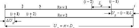
In Figure 6, it is depicted that
i
cusps are created in the first grinding wheel revolution. In the 2nd revolutionof the grinding wheel the
i
+1 th diamond grit produces a cusp that has a ∆Us phase difference with the first one. In the 3rd revolution this difference reaches to2∆Us , and so on. This process continues until the phase difference between the 2nd cusp in the 1st revolution and the 1st cusp in the n-th revolution reaches to less than∆Us . The profile created in this situation is named steady profile (Fig. 7) and remains unchanged. This means that increasing the number of dresser revolutions only makes this profile extended towards the center of the grinding wheel such that its shape does not change. ∆Us is needed to simulate the grinding wheel surface after dressing with the hand set rotary roll dresser. To determine∆Us , the number of diamond grits that are engaged with grinding wheel in each revolution must be determined. Byzmec suggests the following inequality [9]:(11)
e s L U i i≥ ′=
where,
i
is the number of diamond grits that are engaged with the grinding wheel in each revolution,U
sis the perimeter of grinding wheel which is equal toπ
×
D
s.e
L
is the distance between two consecutive cusps (Fig. 5). Since Us/Le has seldom an integer value,i
isconsidered as the first integer number and is greater than
i
′
. Before the start of 2nd revolution, thei
thdiamond grit engages with the grinding wheel in a Us−(i−1)Le distance from the
i
-1 th diamond grit in the 1st revolution. Therefore, the phase difference (∆Us) will be equal to:(12)
s e
s i L U
U = × −
∆
Figure 7: Intersection of cusps in different revolution and creation of steady profile.
B. 2D Computer simulation
According to the required time to create a cusp and also the chosen time step, a 2D shape of the cusp can be plotted. In the 2nd revolution, the 1st cusp is shifted in the peripheral and radial directions as much as ∆Us and
a
r respectively. The simulation and its consequent shift would be continued until a steady profile is formed. When this occurs, the final steady profile of grinding wheel surface can be plotted. Using this simulation and with regard to achieved steady profile, the roughness and the quality of grinding wheel surface would be predicted. C. 3D modeling2D modeling illustrates only the peripheral roughness of the grinding wheel surface. In order to investigate the lateral roughness of the grinding wheel surface, the dimension of cusps in
Z
direction should be determined.The modeling process for generating 2 dimensions of a cusp was discussed. In this section, the following equation was derived to determine the third dimension of a cusp. This is with regard to the assumption that the diamond grit has a truncated cone shape.
(13) +
< < + − +
+ < < −
− < < − − +
=
2 2 )
(
2 2 )
(
2 2 )
(
) , (
d d
d Z f f Z X Y
f Z f X
Y
f Z d f Z X Y
Z X Y
where, dd is diameter of the outer circle of the truncated cone and
f
is the flatness of diamond grit as shown in Fig. 2. Using (13), a 3-D plot of a cusp can be generated, while there are many diamond grits which would create cusps. Therefore, the overlaps of cusps should be considered in 3D modeling just as 2D. The arrangement of the grits on the dresser surface plays an important role in determining the 3D plot of the grinding wheel surface after the dressing process. One of the most common arrangements of diamond grits on rotary dresser surface is shown in Fig. 8 [9]. In the proposed model, the same arrangement was assumed. According to Fig. 8, grits are not arranged successively in lateral direction. Thus the created cusps have a phase difference in lateral direction which leads to an increase in lateral roughness. In this figure, Lra is the distance between two consecutive grits in lateral direction. To determine the topographical shape of grinding wheel surface, onlye
ra L
L × rectangular grid section should be plotted. In this rectangular grid section, 15 steady profiles are created.
1st revolution
1
i+
2i+1 3i+1
r
a
s
U
e
L
Figure 8: Most common arrangement of diamond grits on hand set roll dresser surface [9].
3. RESULTS FROM THE THEORETICAL MODEL
The 3D simulation outputs for coarse and fine dressing are shown in Fig. 9. On the basis of this model, the effect of different rotary roll dressing parameters on grinding wheel surface roughness is theoretically discussed. The aim is to establish appropriate dressing process configurations. The results are shown in Fig. 10 and the following points can be discussed:
1- When the speed ratio between dresser and grinding wheel is close to 1, the grinding wheel surface roughness increases. This is responsible for increasing the dressing forces. Consequently, the rotary dresser might be damaged due to very high dressing forces.
2- The roughness of the wheel surface will be low if the curvature of the cusps is low. Therefore, in the finishing pass, a low feed for rotary dresser, and speed ratio of around -0.8 is suggested.
3- In high efficiency dressing (high removal rate), the speed ratio must be as close as 1 and the feed of rotary dresser must be high. When the steady profile is formed, if the dressing process continues this profile remains unchanged. As a result, prediction of the number of revolutions to reach the steady profile is useful during dressing. This can save the time and cost of the process by applying the required number of revolutions.
Figure 9: 3D Grinding wheel surface from analytical simulation with a) fine and b) coarse dressing parameters.
0 50 100 150 200 250 300 350 400
-0.8 -0.4 0 0.4 0.8 1.2
-Figure 10: Theoretical grinding wheel roughness versus speed ratio for different rotary dressing infeed.
4. EXPERIMENTAL RESULTS
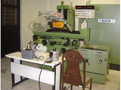
To verify the presented model, an experimental set up was arranged which is illustrated in Fig. 11. The hand-set rotary dresser was coupled on the output shaft of an electric motor. The rotational speed of this electric motor was adjusted by controlling its input voltage. Dresser feed was accomplished by passing the rotary dresser system under the grinding wheel at the velocity of
v
while removing the radial deptha
rfrom the wheel. Maintaining precise control of the dressing infeed rate required precise regulation of the table speed. The hydraulic system for controlling the surface grinder motion was suitable for accurate and repeated selection of the slow speed required. The machine tool used in experiments was HAUNY BLOHM HFS 204. The rotational speed of the surface grinder spindle, varied between 0 through 4500rpm
. Furthermore, maximum achievable peripheral grinding wheel velocity was 32m s/ with the wheel diameter of 140mm. All experimental resultsreported are for the wheel with
specification
32 46 8
A
I VBE
. This is a single crystal aluminum oxide abrasive in a vitreous binder withmm 5 .
12 width. The grinding wheel and the dresser were produced by WINTER Company.
Figure 11: Photograph of dressing rig used for this research.
ra L
e L
r
a =1 5 m. µ
r
a =3 mµ
r
a =6µm
r
a =7 5 m. µ
(a)
(b)
The workpiece material was AISI1045 with 3
10 10 10× × mm dimensions. Wheel and work piece surface roughness were measured by a profilometer. The details of measurement methods are described in [14]. The effect of dressing parameters, on grinding wheel and workpiece roughness were investigated.
5. RESULTS AND DISCUSSION
Figure 12 shows the surface of the aluminum oxide grinding wheel after dressing. The trace ‘a’ and ‘b’ show a circumferential groove in the wheel periphery (wheel structure is under trace) created during a dressing cycle. Trace ‘a’ shows the wheel profile after 5 fine dressing passes using 8
µ
m radial infeed and speed ratio of−0.4. The wheel surface after coarse dressing is shown in trace ‘b’ with 16µ
m radial infeed and +0.8 speed ratio. Correlation between grinding wheel roughness(
R
a)
, speed ratio(
q
r)
, and radial infeed(
a
r)
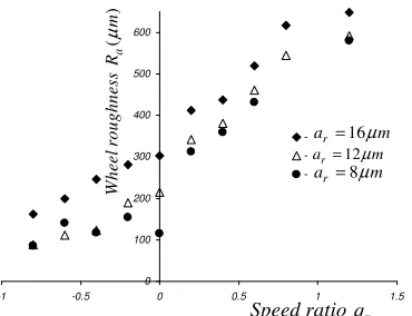
are shown inFigs. 13 and 14. These figures show average roughness of grinding wheel. The values were calculated by averaging four dressing passes at each run and using standard statistical techniques.
- The positive speed ratio, in Fig. 13, implies a high dependence of
R
a onq
r . This dependency grows weakwhen the speed ratio is negative. In this situation (negative speed ratio), the formation of wheel topography is achieved by deformation of the aluminum oxide abrasive.
By contrast, in dressing with positive speed ratio, it appears that the abrasive grain tips on the coarsely dressed wheel were extensively fractured during the dressing process.
Figure 12: Profile of wheel surface after dressing with a) fine and b) coarse dressing parameters.
0 100 200 300 400 500 600
-1 -0.5 0 0.5 1 1.5
Figure 13: Variation of wheel roughness versus speed ratio.
- From Figs. 13 and 14, it can be seen that variation of the speed ratio as compared with radial infeed has a bigger effect on grinding wheel roughness. Therefore, speed ratio has extensive affects on fracturing and dislodging of the grits from the bond material which surrounds them.
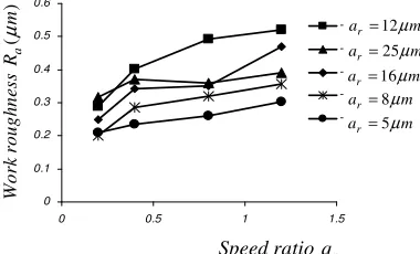
Fig. 15 shows workpiece surface finish achieved after different dressing runs. It is clearly apparent that unidirectional low speed ratio promotes good workpiece surface finish. Conversely, the results show that higher unidirectional speed ratios give coarser surface roughness. It is evident that the resultant work piece surface finish obtained from grinding wheel after dressing does not necessarily increase in the same order as wheel surface roughness increase. This is shown graphically in Fig. 16. The speed ratio and dresser infeed rate have also similar influence on part surface roughness as shown in Fig. 15.
Table 1 shows the influence percentage of dressing parameters on roughness obtained using ANOVA. It is clear that the speed ratio has the greatest influence, about 71%, on grinding wheel roughness. While radial infeed of dresser has 29% effect on grinding wheel surface roughness. Evidently, the effect of speed ratio (51.7%) and infeed (48.3%) on work piece are the same. This may be due to the plastic behavior of workpiece through the grinding process.
0 100 200 300 400 500 600 700
0 5 10 15 20 25 30
Figure 14: Variation of grinding wheel roughness versus dressing infeed rate for various speed ratios.
(a)
(b)
16 r
a = µm
12
r
a = µm 8 r
a = µm
r
Speed ratio q
( ) r
feed rate a µm
0.8 r
q = +
0.6 r
q = +
0.4 r
q = +
0.2 r
q = −
0.4 r
q = −
0.6 r
q = −
(
)
a
W
h
ee
l
ro
u
g
h
n
e
ss
R
m
µ
(
)
a
W
h
ee
l
ro
u
g
h
n
es
s
R
m
Furthermore, the speed ratio has the greatest influence on the dislodging of grits during dressing. This is in line with work done by Malkin and Murray [2], [3].
Comparison of the mathematical model and experimental results is shown in Fig. 17. It can be seen that in dressing with negative speed ratio the results compare well. But in the positive speed ratio they have more discrepancies and the experimental results are typically 2-3 times larger than the modeling result. In positive speed ratios, formation of wheel surface involves fracture of the abrasive grits. But in modeling, the brittle fracture is ignored and it was assumed that the grinding wheel is made of an isotropic material in which brittle fracture dose not occur. When the speed ratio is negative, the formation of grinding wheel surface is based on the plastic deformation of abrasive grain [2], [3]. It results in a smaller probability of fracturing. Therefore, as shown in Fig. 17, the experimental and modeling results are similar. The relative amount of deformation and fracture of alumina grits which occur during rotary dressing extensively depends upon the speed ratio. The development of fracture and grit dislocation model would result in a more ‘natural looking’ surface profile.
0 0.1 0.2 0.3 0.4 0.5 0.6
0 0.5 1 1.5
-Figure 15: Variation of work piece roughness versus speed ratio.
0.1 1 10 100 1000
0 0.4 0.8 1.2 1.6
Figure 16: Wheel and work piece roughness versus speed ratio. TABLE 1
PERCENTAGE OF THE INFLUENCE OF DRESSING PARAMETERS ON
ROUGHNESS.
Speed ratio(qr) Dressing radial
infeed(ar)
Measured parameter
%71 %29
Wheel roughness
%51.7 %48.3
Work piece roughness
0 100 200 300 400 500 600 700
-1 -0.5 0 0.5 1 1.5
Figure 17: Comparison between wheel roughness resultant from theoretical modeling and experimental result.
6. CONCLUSION
Experimental results indicate that rotary dressing involves both plastic deformation and fracture of the alumina abrasive grits. With finer dressing conditions, relatively more deformation and less fracture is observed. Fracture can occur either at the vitreous binder (bond fracture) leading to wheel grits dislodgement, or within the grits (grit fracture).
In dressing with negative speed ratio the presented mathematical model and experimental results compare well. But in the positive one, they have more discrepancies. This can be due to formation of wheel surface by fracture of abrasive grits which is ignored in the model.
In positive speed ratio the wheel roughness extensively rises with increasing speed ratio. But such rise is not observed in negative speed ratio.
The same type of behavior between dressing parameters, roughness of grinding wheel and workpiece roughness was observed. With same dressing parameters, the grinding wheel surface roughness is about 1000 times greater than workpiece surface roughness.
The effect of dressing speed ratio and dressing infeed on workpiece surface roughness are the same. But the speed ratio has the greatest influence on grinding wheel surface. This is due to behavior of grinding wheel as a brittle material.
7. NOMENCLATURE
r
a
Dresser infeedd
d
Diameter of the outer circle of thetruncated cone shape diamond grit
d
D
Mean diameter of diamond grits on thedresser surface
r
D
Diameter of rotary dressers
D
Diameter of grinding wheelf
Flatness of diamond grit Grinding wheel roughness at ar =8µmWork piece roughness at ar =8µm
Real wheel roughness
at ar=8µm
Predicted wheel roughness at ar =8µm
25
r
a = µm
16
r
a = µm
12
r
a = µm
8
r
a = µm
5
r
a = µm
r
Speed ratio q
(
)
a
W
h
ee
l
ro
u
g
h
n
e
ss
R
m
µ
r
Speed ratio q
(
)
a
W
o
rk
ro
u
g
h
n
es
s
R
m
µ
(
)
a
R
o
u
g
h
n
e
ss
R
m
µ
r
i
Number of diamond grits that areengaged with the grinding wheel
e
L
Peripheral distance between twoneighbor cusps
ra
L
Distance between two consecutive gritsin lateral direction
d
N
Number of consecutive diamond gritsr
q
Speed ratioa
R
Surface roughnessr
S
Peripheral lead of rotary dresser pergrinding wheel revolution
t
Time needed to create one cusp on thegrinding wheel surface
m
T
Lateral distance between two neighborcusps
s
U
Perimeter of grinding wheels
U
∆
Phase difference between created cuspss
V
Peripheral velocity of the grindingwheel
X
Dimensions of a cusp in the peripheraldirection of grinding wheel surface
Y
Dimensions of a cusp in the radialdirection of grinding wheel surface
Z
Third dimension of a created cuspr
ω
Angular velocity of rotary dresserS
ω
Angular velocity of grinding wheelθ
Angle between two cuspsα
Contact angle between dresser and grinding wheel8. ACKNOWLEDGMENT
Authors wish to thank Dr. A. Abdullah for his valuable help in the experimental program. The assistance given by the staff of the Machining Research Laboratory of Mechanical Engineering department of Amirkabir University of Technology is also acknowledged.
9. REFERENCES
[1] J. Verkerk, ”The effect of wheel dressing on wheelwear ,work surface roughness and surface integrity,” SME ,Int. Eng. Con. ,may 1977, p276-283.
[2] S. Malkin, T. Murray, “Mechanics of rotary dressing of grinding wheels,” ASME, 1977, p95.
[3] S. Malkin, T. Murray, “ Effect of rotary dressing on grinding wheels performance,” ASME ,V.100 ,1978, p297-303
[4] E. Brinksmeier, M. Cinar, "Characterization of Dressing Processes by Determination of the Collision Number of the Abrasive Grits," Annals of the ClRP Vol. 44, 1995,p299-304.
[5] Z. Pruzak, J. A. Webster, I. D. Marinescu, "Influence of dressing parameters on grinding performance of CBN/Seeded gel hybrid wheels in cylindrical grinding," Int. Jou. Production Research, 1997, Vol.35: P2899– 2915
[6] H. Baseri, S. M. Rezaei, A. R. Rahimi, M. Rezaeian, "Modeling of Disc Dressing Forces," Machining Science and Technology, Vol. 11, N. 2, April/June 2007,p201-216
[7] H. Baseri, S. M. Rezaei, A. R. Rahimi, M. Saadat, "Analysis of the disc dressing effects on grinding performance PART 1: Simulation of the disc dressed wheel surface," Machining Science and Technology, Vol. 11, N. 2, April/June 2007,p183-196.
[8] H. Baseri, S. M. Rezaei, A. R. Rahimi, M. Saadat, "Analysis of the disc dressing effects on grinding performance PART 2: Effects of the wheel topographical parameters on the specific energy and workpiece surface roughness," Machining Science and Technology, Vol. 11, N. 2, April/June 2007,p197-213.
[9] M. Byzmec, “Computer visualization of grinding wheel surface after rotary rotary truing,” university of Connecticut, 5th Int. grinding conference, SME, 1993,p143-152.
[10] J. Darnbrough, “ An evaluation of the suitability of diamond rotary dresser for the dressing of the grinding wheels,” university of Bristol , B. S. thesis , 1985.
[11] R. B. Mindek, “Improved rotary rotary truing of hot pressed CBN grinding wheel,” University of Connecticut, B. S. Thesis, 1992 [12] S. Malkin,T. Murray, ”Comparison of single point and rotary
dressing of grinding wheels,” North american metal working research conference , may 1977,p311-320
[13] S. Malkin, “Grinding technology : theory and application of machining with abrasives , Ellis Horwood , Chichester , UK , 1989 , Chapter 8 , PP.197-221
![Figure 1: Byzmec Model [9].](https://thumb-us.123doks.com/thumbv2/123dok_us/8944889.1854257/2.612.314.525.66.215/figure-byzmec-model.webp)