Strojniški vestnik - Journal of Mechanical Engineering 53(2007)7-8, 442-461 U D K -UD C 658.512.2
Izvirni znanstveni članek - Original scientific paper (1.01)
Konstruiranje izdelka s pomočjo tehnike optimizacije stika
Product Design Using a Contact-Optimization Technique
Istvän Päczelt - Attila Baksa - Tamàs Szabó (University o f Miskolc, Hungary)
Znano je, da v inženirski praksi nastajajo velike napetosti zaradi oblik in obremenitev teles v stiku. Porazdelitev napetosti običajno ni enakomerna, singularnosti pa skrajšujejo dobo trajanja strojnih elementov. Zato je pomembno z ustreznim oblikovanjem stikov odpraviti omenjene singularnosti. Eden od ciljev prispevka je predstavitev metode, ki rešuje problem singularnosti v stikih. Z nadzorom dotikalnega tlaka lahko dosežemo enakomerno porazdelitev dotikalnega tlaka. Postopek optimizacije upošteva mejne napetosti materiala. V prispevku obravnavamo dva tipa dotikalnih problemov. Najprej analiziramo dotikalne probleme s predpostavko o linearni elastičnosti in majhnih deformacijah ter ustaljeno obrabo. Dva numerična primera pojasnjujeta ta postopek. Obravnavani so tudi parametri nadzorne funkcije, ki omogoča največjo nosilnost, kar je uporabno za konstruiranje zavor in ležajev. V drugem delu prispevka obravnavamo rešitev dotikalnih problemov za velike pomike in deformacije. Za primer je zračna vzmet, pri kateri primerjamo računske
vrednosti krivulje nelinearnega pomika z rezultati meritev. © 2007 Strojniški vestnik. Vse pravice pridržane.
(Ključne besede: metode končnih elementov, konstriranje izdelkov, optimiranje stika, iteracije)
It is well known that in engineering practice high stresses occur and that these stresses depend on the shapes and the loads o f the bodies in unilateral contact. The stress distribution is often not smooth and has some singularities, thereby decreasing the lifetime o f the machine elements. It is an important objective to obtain a smooth stress distribution when optimizing the shape o f the elements. One o f the goals o f this paper is to present a method that resolves the above problem. By controlling the contact pressure a prescribed, smooth contact-pressure distribution can be achieved. The optimization problems take into account the limit stress constraints o f the material. In the present paper two types o f contact problems are investigated. Firstly, contact optimization problems are analyzed assuming linear elasticity and small displacements, including steady-state wear process. Two numerical examples are presented on this topic fo r a rolling machine element: a punch optimization and a shape optimization. We also investigated which parameter values o f the controlling function result in the maximum loadability. This can be useful in the design o f brakes or bearings. In the second part o f the paper the solution o f the contact problem fo r large displacements and deformations is investigated where an air-spring is analyzed by calculating the nonlinear load-displacement curve and comparing it with measurements.
© 2007 Journal o f Mechanical Engineering. All rights reserved.
(K eywords: finite elem ent m ethods, product design, m echanical contacts, contact optim ization, iterative methods)
0 INTRODUCTION
In engineering practice, connections between machine elements are frequently modeled as unilateral contact problems. Comparatively few studies can be found in the literature for contact optimization [1]. Nevertheless, a thorough mathematical investigation o f the subject can be found in [2], and in [3] the contact problems o f wearing processes are investigated in an analytical way.
The elimination o f stress singularities is an important engineering task. In order to overcome this problem, the application o f contact-pressure control is recommended, since this ensures a smooth contact-pressure distribution as well as a zero value on the part o f the border o f the contact zone.
to o k into account the stress limit in the case o f solving contact-optimization problems for axially sy m m etrical bodies. The equivalent von M ises stress (7 must be under a prescribed limit (<r ). The p r e s e n t p a p e r extends the load cases fo r the exam ined numerical examples; in addition to the external force load here the kinematical loads can a ls o b e a p p lie d on the c o n ta c tin g p a rtic le s. D iscretization o f the domain with /^-version finite elem ents is advantageous [7], since it results in rapid convergence, and high-order mapping ensures an accurate geometry for the shape optimization.
The lifetime o f a roller bearing is influenced b y m any parameters, e.g., the type and the shape of the rollers, the number o f rows, the shapes o f the tracks o f the bearing rings, the bearing dimensions, th e m aterials and their treatm ent, the quality o f manufacturing, etc. A number o f papers, e.g., [8] to [ 13] are devoted to the issue o f the roller’s rounding- off. In these papers, except the last one, the radius of th e rounding-off that results in a generally non sm ooth contact pressure distribution is given.
D ifferent ro u n d in g -o ff tech n iq u es, e.g., cylindrical or conical rollers, have rounding-off w ith a given radius at the ends, but it is also possible to m ake rounding-off a logarithm ic function o f radius, as published in [14] and [15]. The problem o f ro u n d in g - o f f is also a n a ly z e d in ca se o f elastohydrodynamic lubrication in [16] and [17]. T h e q u estio n o f ro u n d in g -o ff is ex am in ed in references [4] and [6] for roller bearings without restrictions for the stress limit. The constraint for the equivalent stress limit is not taken into account in the papers referenced above, but due to the loadability it is required.
In the present paper the equivalent stress lim it is considered through the optimization process as a constraint. The optimal shape is achieved by an iteration-based algorithm (see [ 18]). A numerical exam ple is presented in Section 2.6.
Sub-section 2.3 o f this paper deals with the w e a r p ro b le m o f the re la tiv e s lid in g o f tw o contacting bodies. The transmittable torque with a clutch and frictional power loss in the case o f brakes are important quantities during the design process, a n d due to w ear the shapes o f the bodies are c h a n g in g . T here are n um erous alg o rith m s to describe the transient wear process ([19] to [21]). T h e se alg o rith m s have huge p ro c e ssin g -tim e requirements. There is also the question o f how we can determ ine the shape o f the bodies and the
contact pressure distribution in the case of steady- state wear without using the algorithms for a time- dependent w ear process. One investigation [18] suggests a technique for the previous problem. The present paper gives a formulation for calculating the wear o f disk brakes in steady-state based on the modified Archard law.
R ecently, the c la ssical springs used in vehicles for suspension have been replaced by air- springs. The advantage o f an air-spring compared to a classical spring is its nonlinear behavior, which can be controlled by the inflation pressure. In addition to the force displacements o f the diagram, the designer is interested in determining the stresses and strains in the reinforcing fibers. Accurate results can be obtained by a /»-extension o f the finite- element method, but its application for problems with large displacements requires much more work. Therefore, a simplification is performed, i.e., the contacting element sides are kept in a straight line, which made it possible to use the algorithm given by Crisfield [22] for the /»-extension elements. A numerical example is presented in Section 4 to demonstrate the working process o f an air-spring.
1 TREATMENT OF THE CONTACT
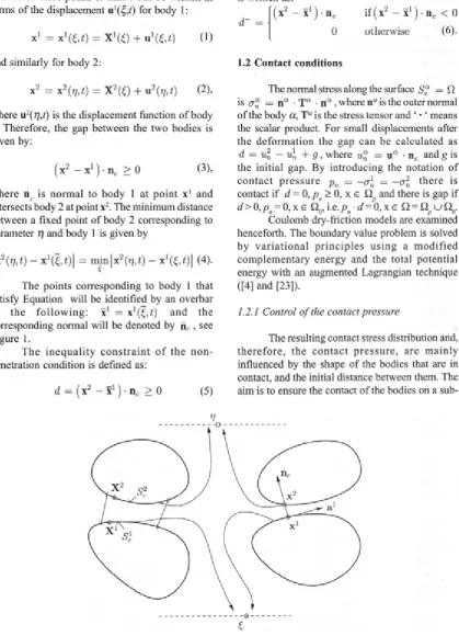
Without the restriction o f generality let us consider the contact problem o f two elastic bodies ( a = 1,2). The surfaces o f the bodies are separated into three regions: S'“ denotes the part o f the body w here displacem ents u 0 are given, in S f the traction t0 is applied, while S " represents the part o f the bodies where the contact is expected. The S “ part o f the body is called the proposed zone o f the contact. The bodies are loaded with the body fo rce ba. We are in te re s te d in fin d in g the displacement vector field the strain A“ and stress T“ tensor fields.
1.1 Contact kinematics \
The contacting surfaces are described in parametric form (see [23]): The contacting surface o f the body labeled a = 1 (or a = 2) is written in terms of the parameters (£ = (£ ’, <^2)) (or t] = ( q 1, t]2)). In the im plem entation the param eters w ill be associated with the element surfaces using optimal approximations based on the Babuška points.
the referen ce co ordinate system . The p o sition vectors o f these points at time t can be written in terms o f the displacement u \^ ,t) for body 1 :
X1 = x 1^ ,* ) = X x( 0 + u 1^ ) (1)
and the penetration function for the penalty method is written as:
d~ = n c
if ( X2 — X1 ) ■nc < 0 0 otherw ise (6).
and similarly for body 2: 1.2 Contact conditions
X2 = x 2(r],t) = X 2(£) + u 2(r],t) (2),
where u 2( r y ) is the displacement function o f body 2. Therefore, the gap betw een the two bodies is given by:
( X2 — X1 ) • n c > 0 (3),
w here n c is n o rm al to body 1 at p o in t x1 and intersects body 2 at point x2. The minimum distance between a fixed point o f body 2 corresponding to parameter rj and body 1 is given by
IX2 (77, t) - x 1^ , f)| = m m IX2(77, t) - x \Z ,t) \ (4).
The points corresponding to body 1 that satisfy Equation will be identified by an overbar in th e fo llo w in g : x1 = x1^ ,^ ) an d the corresponding normal will be denoted by n c , see Figure 1.
T he in e q u a lity c o n s tra in t o f th e n o n penetration condition is defined as:
d = ( x2 — X1 ) • n c > 0 (5)
The normal stress along the surface 5 “ = ft is er“ = n“ • T “ • n " , where n“ is the outer normal o f the body a,T “ is the stress tensor and ‘ • ‘ means the scalar product. For small displacements after the d efo rm atio n the gap can be calcu lated as d = u l - u\ + g, where w“ = 11“ • n c and g is the initial gap. By introducing the notation o f c o n ta c t p re s s u re pn = = —cr2 th e re is contact if d = 0 ,p n> 0 ,x e Q and there is gap if d > 0 ,p = 0 , x e Q .,i.e.p d= 0 , x e Q = Q u£2„.
Coulomb dry-friction models are examined henceforth. The boundary value problem is solved by v a ria tio n a l p rin c ip le s u sin g a m o d ifie d com plem entary energy and the to tal p o tential energy with an augmented Lagrangian technique ([4] and [23]).
1.2.1 Control o f the contact pressure
The resulting contact stress distribution and, th e re fo re , th e c o n ta c t p re s s u re , are m ain ly influenced by the shape o f the bodies that are in contact, and the initial distance between them. The aim is to ensure the contact o f the bodies on a
sub--o
dom ain, indicated by Qc (here is only a line), and o n that contact surface the pressure varies as a p re s c rib e d fu nction. This is ach iev ed by the m odification o f the shape of the contacting parts. T he rest o f the supposed contact domain Sc = ft, w hich is £2nc where the pressure distribution is not k n o w n , but it m ust be less than a prescribed function.
In our optimization problems it is supposed th a t the bodies are in contact on the whole sub- dom ain £2 o f the contact zone S = £2. The contact
c c
surface is m odified in a way that the following function holds true for the contact pressure
Pn < X' = vi X) pmax, X
e
n c
= [s,f = 0] (7),w here the chosen control function must satisfy the condition 0 < v(x) < 1, and
7W = m a x p„( x ) , x = [s,i] (8),
w here s and t are surface coordinates in the region £ 2c . In the sub-domain Q = nc (Q = Qv c u QncJ ) the fulfillm ent o f the following inequality is required
X(x) =
v ( x ) pmax - pn ( x )> 0, X e
Qnc
(9).
The definition o f the control function is arbitrary. In order to avoid the singularities in the
stress distribution practically, it is defined in such a way that not only the value o f the function must be zero at the end o f the control zone but also the first derivative in a sort o f direction as well.
Therefore, let us define a function v(s) o f class C1 in the sub-region £2 (see Figure 1). The normal shape variation is assumed to be specified by a function v(s) o f class C' in the sub-region £2 We introduce the functions depending on the coordinate s :
- ^2
= h + (/a - /2)
/2 > 0, /3 > 0
~ ^2 (10)
and V(s) = 0, v(«) = r w
V(fi) = V ( s ) ,
v w = r w
-V(») = 0,
3(s — Xj Li * Li)2 - 2(
» - A
L l—Ly
l-3(
8- L3L<1 — L'f + 2( s ~ L3
La — La
(11),
! »
r =r 0)e e fj
r = r (1)= r (2) ' i M 'i
t
V ?
Boundary cond. : u=v=w=0 r (2)
b=b<’>
b<2>
W i r
k .
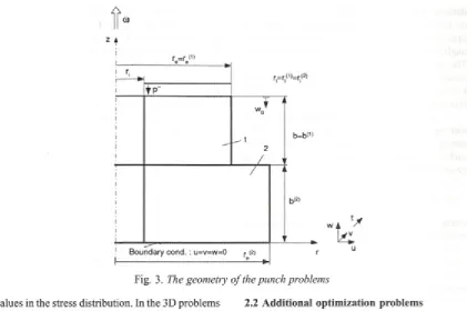
Fig. 3. The geometry o f the punch problems
values in the stress distribution. In the 3D problems in paper [24] it is supposed that the upper body has a rigid translation and rotation, Q is a line and the rotation vector is perpendicular to this line. The control function along direction t is v(t) = 1, i.e.
v e x ) = V cs) v(t) (12).
2 SHAPE OPTIMIZATION FOR SMALL DISPLACEM ENTS
2 .1 P u n c h p r o b le m s
Axially symmetrical machine elements are applied in m an y in d u s tria l c o n s tru c tio n s . T he fo rce d istrib u tio n betw een the bodies gives a strong influence on the stress state o f the construction. A designer always endeavors to avoid singularities within the contact region in order to keep stresses at a lower level. I f the control pressure function is used, the contact stress can be easily achieved w ithout a stress singularity.
In our investigation the same examples are given for different object functions with the control o f the contact pressure distribution. The geometry o f the punch construction is shown in Figure 3.
In [6] a couple o f c o n ta c t-o p tim izatio n problem s can be found for punches. Here, some new , a d d itio n a l o p tim iz a tio n p ro b le m s are formulated.
2 .2 A d d it io n a l o p t i m iz a t io n p r o b le m s
In engineering practice rotating particles usually transmit torque. The torque is defined as:
re
Mt = p j 2 i r r 2pn dr (13), n
where p is the coefficient o f friction.
Let us denote the angular punch velocity by co and specify the dissipation power due to frictional sliding at the contact surface by:
rc
DF = Jt„ ■ uT = o jp J27tr 2pn dr = Mt uj ( ^ )
-sc n
A ssum e now that the punch rotates with respect to its axis with the angular velocity co, and the uniform vertical displacement w() is prescribed on the top surface o f the punch.
C o n s id e r th e p ro b le m o f to rq u e maximization, assuming the parameters L l and L2 are unspecified and Ly L4 and L2- L t are fixed. M aximize the torque M T by determining the initial gap function g = g(s), so that g(s.) = g mm = 0, where s = r - r . and r. is the internal punch radius, thus the optimization problem is
P P 1 :
m ax -f Ad'f I pn > 0, d 0, Qmm 0,
sW-L 1 1 (15).
In order to minimize the dissipation power o r torque, assume that L, = 0, L2 = 0 and Z4 - L) are fix e d ; how ev er, L 4 and L 3 m ay vary. The optim ization problem is now formulated as follows PP2 :
m in \D F \Vn > 0 , d = 0, 2min = 0,
1 (16).
X = X (s,Pn,L4 ) = 0, cre < au >
Using the optimization problems PP1 and PP2 different initial shapes o f the punch surface are obtained.
2.3 Investigation o f the wear process
Sliding particles that are in contact are continuously losing some material, i.e., wear occurs. Practically, it is important to know the rate o f wear and the contact-pressure distribution during the wear process. When steady-state occurs during operation the information about the shape o f the bodies and the stress distribution between them is significant.
Firstly, let us formulate the problem o f the m inim ization o f the wear volume rate at the contact interface. Assuming the specific wear rate w to be dependent on contact pressure, the relative slip velocity
vr
= ||ur || and the contact shear stress T„ = ||t„II
, i.e. w = w(pn,Il
ur ||,||t„II)
, the total w ear volume rate is:W = J ' w d S (17)
Sc
an d the w ear dissipation pow er at the contact surface S is equal to:
D,„ == J p „ w d S (18).
The o p tim izatio n p ro b lem can now be fo rm u lated as follow s. A ssum e that the punch rotates w ith respect to its axis w ith the angular v e lo c ity co, and th e u n ifo rm v e rtic a l tra ctio n a z = —p is exerted on its top boundary with the resulting force F0 = 7r ( re2 — j f ) p . Then the gap function must be determined in order to minimize
W or D , thus PP3 :
min \ W, D,. P n >
0,
d= 0, Fp - F0 = 0 ,
X = X ( s , P n , h ) = 0, 5min = 0 }
(19),
w here Fp — 2tt f pnr dr is the contact force.
A ssum e that the w ear rule satisfies the modified Archard law [25]:
W = ß ( p p n )b V r = ß p b P n < = 0 P n V“ (20),
where a, b, ß are the wear parameters, u is the friction coefficient, p n is the contact pressure, ß = ßfib , and the re la tiv e v e lo c ity is Il ur II = vr = no . T he sh e a rin g stre ss in the contact surface xn calculated from the contact p ressu re by the C oulom b dry frictio n law is T = u p .
In [18] it is dem onstrated that the wear dissipation power at the contact surface is minimal in th e ste a d y sta te o f th e w ear p ro c e ss and corresponds to the uniform wear rate. However, the m inim ization o f the w ear volum e rate and the frictio n d issip atio n pow er is not su itab le for describing the steady-state wear process.
Using the minimum o f the wear dissipation power the contact pressure is:
F r*
pn = w here I D = 2 n / r 1-^ dr (21).
In. w J
The wear rate is uniform along the radius
[ I DW ßu ja = const (22).
The wear volume rate is
W = J 'w d S = 2-7T
•e
P
‘
.a { F 0 r dr
= ßuja A .
. I D „ ,
(23).
W n
W hen the upper body, e.g., a disc brake o f a vehicle, is a segment o f a rotationally symmetrical body with angle <t>, then Equations to remain valid, replacing b w with I'd :
'e
j w = $ J r 1-* dr (24).
PP4 : H ere the o p tim izatio n problem is the following:
[Dw j pn > 0, d = 0, Fp — F0 = 0,
P n =
0,
(25)
minX = x(u
P n )9 m i n
Ü }
A r - i /■(■*■)
1 D „ .
The importance o f these results is that the shape o f the contacting bodies and the contact pressure after wear are determ ined in the case of steady-state processes w ithout solving the time- dependent wear problem.
2.4 Solution o f the optimization problems PP1 -PP4
A fter the discretization o f the optimization p ro b le m a n o n -lin e a r p ro g ra m m in g p ro b le m evolves, w hich is solved by a special iteration process. We distinguish two types o f iterations. In the first one, w hich w as introduced in [4], the optim al shape is determ ined w ith the prescribed control parameters f 2, f v L., i = 1,...4. The second type o f iteration is an extension o f the first one, w ith the stress constraint prescribed for the von Mises equivalent stress cr, <7 < (7, where cr is the ultimate stress [6],
W hen the stress constraint max a < a is
e u
imposed at any Lobato integration points the values o f the parameters assumed as fixed or specified in the first type iteration, should be updated in order to satisfy the stress constraint. Denote collectively the parameter that should be updated in the second type o f iteration by f.
The “loading” process is characterized by the variable istep. The value o f / is calculated using the following formulae:
/ = /o + A / (istep +1) (26),
where /j and A/'are chosen in advance. For instance, for the Problem PP1 f= = r , and Af= 0.1 (r - r). The optimization problem is solved by the first type o f iteration at the fixed f . At each /stcp a new shape is determined for the upper body.
The effective stress value a is calculated at
e
the Lobato integration points o f the finite quadratic elements. We assume that for the value f = f the effective stress is cr* < a u and at the next loading i the param eter f - f * and the effective stress exceeds the ultimate value a** > cru
-The optimal value o f / = / ' pt<‘) is searched for in the interval / < / p,(0 < / * using the following linearization process:
j-opt(i) _ j * _|_ ^ 1) (27),
w h e re /* (0) = / * , a **^ = a*e* . At each step o f the
second ty p e o f ite ra tio n the co n tact shape is specified in the first iteration-based process. The second type o f iteration proceeds until
k - o r (i)|
< 0.01 (28). rrr u
2.5 Example for PP1
The fo llo w in g m aterial p aram eters are a ssu m ed : Y o u n g ’s m o d u lu s E = 2 1 0 5 M Pa, Poisson’s ratio v = 0.3, ultimate stress o = 250 M Pa and friction coefficient / 1 = 0.25.
The geometrical parameters are defined as re(1) = 120 mm , r.a)
> )
r.(2) = rj = 20 m m ,
140 m m, bm = ba> = b = 50 mm (see Figure 3). The boundary conditions are prescribed as follows: the cylindrical surfaces r = r. and r = re<a) are traction free tj-/1 ’ = 0 , the bottom surface z = 0 o f the body B2 is constrained, u = v = w = 0 and at the upper surface z = 2b o f punch B, is loaded by the axial displacement w(| and is subjected to the rotational motion v = rcot.
The value o f w0, w hich is the prescribed displacement o f the upper body, is determined in order to achieve the same specific strain in the cylindrical bodies w ith the height o f bm + ba>. It means that: ]00Wf|
-7TT--- 7PT = 0.1% . 6(1) + 6(2)
I f the radius o f the cylindrical bodies is the same and the Young’s modulus E = 2-105 MPa then th is sp e c ific stra in w ill p ro d u c e a 200 M Pa compressive stress. Since the outer radius o f the lower body is greater than the upper body’s, i.e., rj2) = 140 m m > , th e s tre ss d is trib u tio n shows a singularity in the position. The aim o f the optimization is to avoid this singularity, which can be achieved by using the O continuous control function defined by (10) to (12).
Using the iteration defined under Section 2.4 the problem PP1 is solved and the results o f these solutions are summarized in Table 1. The results are calculated for different values o f b = bm = bn\
Mesh of the bodies, wQ=0.12 mm
r [mm]
Length L1 50
1 2 3 4 5 6 7 8 9 10 Number of solution
Effective Mises stress maximum 1400. ... ...
1200
1 2 3 4 5 6 7 8 9 10 Number of solution
My'p/106 - 300 moment in Nmm
1 2 3 4 5 6 7 8 9 10 Number of solution
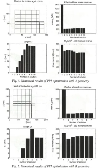
Fig. 4. Numerical results o f PP1 optimization with A geometry
Mesh of the bodies, wQ=0.20 mm 200 r--- --- --- --- n
150
E E 100
50
0'--- ---- ---- ---- ---- L-1--- ---1
0 50 100 150 200
r [mm]
Length L1
1 2 3 4 5 6 7
Number of solution
Effective Mises stress maximum
1 2 3 4 5 6 7
Number of solution
M ^^/106 - 300 moment in Nmm 600
1 2 3 4 5 6 7
Number of solution
Fig. 5. Numerical results o fP P l optimization with B geometry
From Table 1 it is clear that for lower values o f b and w() in case o f max M T the maximum o f the equivalent stress is lower than the ultimate stress, i.e., a < o and the condition a = o is ensured only by increasing the distance L v but it results in
r[m m ] r [mm]
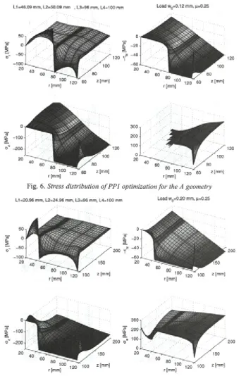
Fig. 6. Stress distribution o f PP1 optimization fo r the A geometry
r [mm] r [mm]
Fig. 7. Stress distribution o f PP1 optimization fo r the B geometry
In Figures 4 and 5 the finite-element mesh and the values o f L { and M f p during the iteration are illustrated. The resulting stress states are shown in Figures 6 and 7, w ith <7 as the radial stress; T. as the tangential shear stress, < 7 as the normal stress
b=60 mm, wQ=0.12 mm, mesh 7*5, istep=1 (-),istep=2(- -)
b=100 mm, wQ=0.20 mm, mesh 7*5, istep=1(-),istep=2(— )
Increasing the value o f b on the top surface, using St. Venant’s theory, there is a linear distribution in the radial direction.
The optimal shapes o f the lower edge o f the upper body are drawn in Figures 8 and 9. This shape
represents the initial gap function betw een the contacting bodies. The definition o f i s t e p = i# can be found in Section 2.4. The curve designated by o belongs to the solution that is fulfilled by the additional condition oema x = o . The labels i s t e p
Table 1. Numerical results o f the optimization problem PP1 Original
Const. B y Maximum M T O W = 0 , , = 2 5 0 MPa
b Wo ° Cmax [MPa] L x [mm] M T [mm] ■ 1 0 9 aemax L x [mm] M T [mm] • 1 0 9
50 0.10 1340.2 10 0.6941 2 22.27 5 6 .8 2 0 .5 9 3 0
60 0.12 1386.3 10 0 .7 0 4 6 2 21.53 4 6 .0 9 0 .6629
70 0.1 4 1420.4 20 0 .7 2 0 9 2 3 4 .7 6 3 8 .7 4 0 .7048
80 0.16 1446.3 20 0 .7 3 5 4 2 3 9 .5 8 3 3 .8 8 0 .7317
90 0.18 1466.4 - - - 2 5 .6 6 0 .7 5 1 0
100 0.20 1482.1 - - - 2 0 .9 6 0 .7 5 9 9
120 0.2 4 1503.8 - - - 16.46 0 .7707
140 0.28 1516.9 - - - 14.11 0.7791
= 6 and i s t e p = 4 indicate that the stage in the iteration-based process belongs to <r** > au (see Section 2.4). To resemble Figures 8 and 9 it is clear that a little change in the gap generates a notable d ifferen ce in a , w hich rem in d s one o f the importance o f accurate manufacturing.
2.6 Optimal shape design o f the rollers
Rolling elements can be found in many types o f engineering equipment. Their requirement for a long lifetime means keeping the stresses smooth and at a low value.
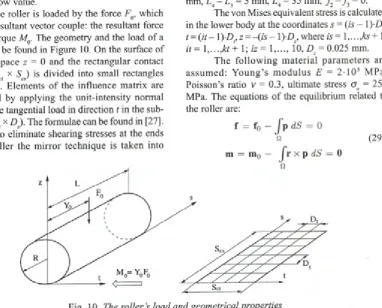
The roller is loaded by the force F(), which gives a resultant vector couple: the resultant force F and torque M(). The geometry and the load o f a roller can be found in Figure 10. On the surface o f the half-space z - 0 and the rectangular contact region (Scl x S J is divided into small rectangles (Z)( X D ). Elem ents o f the influence m atrix are com puted by applying the unit-intensity norm al load or the tangential load in direction t in the sub- region ('D X D ). The formulae can be found in [27]. In order to eliminate shearing stresses at the ends o f the roller the m irror technique is taken into account.
For the case when the load is not applied to the center o f the roller two types o f problems were investigated in an earlier investigation [13].
In this study we analyzed the case when the stress co n stra in t is ta k e n into acco u n t in the optimization process.
Examples. The radius o f the roller is R0
=
60 mm. The roller is subjected to loads o f F0 = 5000 N in the middle. The proposed contact region (1 x 35 mm) is divided into kt-ks = 40 x 100 rectangular e le m e n ts a lo n g the d ire c tio n s t and s. The parameters o f the control function are L { = 0, L2 = 5 mm, L4- L 3 = 5 mm, L4 = 35 mm, f 2 = f = 0.The von Mises equivalent stress is calculated in the lower body at the coordinates ,s' = (is - l) D t, t — (it— 1 ) Dt, z = - ( i s - 1)-D7, where is = l ,...,f e + 1; it= 1 ,...,kt+ 1; iz= 1,..., 10, 0 = 0.025 mm.
The fo llo w in g m a te ria l p a ram eters are a ssu m ed : Y o u n g ’s m o d u lu s E = 2 1 0 5 M Pa, Poisson’s ratio v = 0.3, ultim ate stress <x = 250 MPa. The equations o f the equilibrium related to the roller are:
f = fn -
fp dS =
0 nm = m 0 -
J r
x
pdS =
0s [mm]
Fig. 11. Equivalent stress distribution at z = 0 mm
c a
e
Fig. 12. Equivalent stress distribution at z = 0.15 mm
w here r is the position vector, p is the vector of contact stress, f is the resultant force and m 0 is the m om ent o f the external load.
The distributions o f the equivalent stress cr at z = 0 and its m aximum value are found at
z = -0 .1 5 mm, as shown in Figures 11 and 12.
s [mm]
Fig. 13. The equivalent stress distribution at z = 0 mm after optimization
s [mm]
Fig. 14. The equivalent stress distribution at z = -0.25 mm after optimization
2.6.1 Optimization problem at a given load
The optimization problem at a given load is formulated as:
m in A L ^^max
P n
> 0,
d >0,
„ l e d ,
pn d = 0 , X > 0 , (30)
from which AL = 3.5 mm is obtained.
w hich is briefly described in Sub-section 2.4. The radius o f the roller is R = R(s), which is used to determ ine the initial gap g(x) = g(s, t) between the bodies.
The distribution o f the equivalent stress is demonstrated at z = 0 mm and z = -0.25 mm, as shown inFigures 13 and 14. Comparing the stresses in Figures 12 and 14, the influence o f the optimization is obvious, i.e., <Tmax is significantly decreased.
2.6.2 O p t im iz a t io t p r o b le m f o r c a lc u la t in g th e l o a d a b i l i t y
From the pr vious optimization problem the stress equality o"max = <7 can be achieved by different rounding-offs o f tl e rollers at different loads, i.e., the rounding-off < epends on the load. Since the control function is i uni-value, only a unique roller shape exists for a given load. Namely, after the num erical calculati ons the designer can select from the round-offs in order to achieve the maximum loadability.
The optimization problem can be written in the following form:
Pn > 0, d > 0, m a x \ P 'n , „
Pnd
~-f = 0, m 0,
= 0, <x„ ' cT n ax <—
(31).
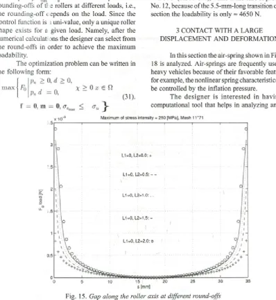
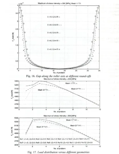
For the different load levels the change in radius along the roller axis can be seen in Figure 15 and 16.
The load value for a different geom etry (problem ) is dem onstrated in Figure 17. The calculation was made with different meshes (kt, ks). The modification o f the mesh does not affect the results. In all cases L, = 0, L = 36 mm and because o f the symmetry i , = Z,4 — L , the change in L influences the loadability.
On the basis o f the numerical results the round-off obtained for the third problem (see Fig. 17) provides the best performance for high loads.
The lo ad ab lity in the case o f con stan t pressure along the meridian is approximately 4850 = 4900 N (case No. 1), while in the case o f problem No. 12, because o f the 5.5-mm-long transition cubic section the loadability is only = 4650 N.
3 CONTACT WITH A LARGE
DISPLACEMENT AND DEFORMATION
In this section the air-spring shown in Figure 18 is analyzed. Air-springs are frequently used in heavy vehicles because o f their favorable features, for example, the nonlinear spring characteristics can be controlled by the inflation pressure.
The d e sig n er is in terested in hav in g a computational tool that helps in analyzing an
X -j o-3 Maximum of stress intensity = 250 [MPa], Mesh 11 *71
5300
5200
5100
“ 5000 (0 - 0 4900 u.
4800
4700
4600
0 2 4 6 8 10 12
No. of problem
Maximum of stress intensity = 250 [MPa] 5300
5200
5100
“ 5000 C0 ° 0 4900
ii-4800
4700
4600
0 2 4 6 8 10 12
No. of problem
Fig. 17. Load distribution versus different geometries Maximum of stress intensity = 250 [MPa]
spring before it is manufactured. One can determine its spring characteristics, the quantitative influences o f the geom etrical m odifications, as well as the stresses and strains in the fiber-reinforced rubber com posite. A finite-elem ent program has been developed, which is based on the following theory.
The axially symmetrical problem is strongly nonlinear due to the contact problem , the large displacem ents and the incom pressibility o f the rubber.
_ d xa
~ d X a (32),
it is modeled with the Hu-Washizu functional, see [26], and the fiber-reinforced layer (/3 = 0) is h o m o g e n iz e d by the so -c a lle d H alp in -T sai equations [28]:
n
H W [u , J , p ) = ßJ W( C ) d V + f u ( j ) d V
V V
+ f p ( j - J ) d V — J u • npdA
V S t
+( l - ß ) l j E . -D-. EdV (37),
where means the double dot product o f two tensors, p is the prescribed pressure and W is the Mooney-Rivlin strain energy density:
W ( C ) = pw ( h e - 3 ) + /% ( h c - 3 ). (38)
in which jU0], /i]0 are the Mooney-Rivlin constants, invariants o f the Cauchy-Green strain tensor:
h e = C u + C22 + C33 (39)
h e = \ ( h c - C - - C ) (40)
where X“ denotes the undeformed configuration, while xa belongs to the current configuration. In the examined problem the lower body is a rigid one; therefore, “ will be omitted in the following.
In o rd e r to tre a t the in c o m p re ssib ility condition we introduce the deformation gradient in a decomposed fonu:
F = FKoiF (33),
where the volumetric part of the deformation gradient is defined as:
FVol = J 1/ 3! (34),
and the Cauchy-Green strain tensors are defined by the different deformation tensors
C = F F (41),
where 1 denotes the transpose o f a tensor,
C = F J F (42).
The II. Piola-Kirchhoff stress tensor for the rubber is given by:
S = 2 ^ + iVC->
and the fiber-reinforced layer is assumed to be linear
where I is the unit tensor. The deviatone part o f the deformation gradient is obtained as:
F = J -1 / 3 F (35)»
and the volumetric change is:
J = d e tF (36).
The incompressibility condition is fulfilled when J = 1.
In our investigation the rubber (ß = 1) is assumed to be a nearly incompressible material and
S = D E (43),
where D is the constitutive tensor and E is the Green-Lagrange strain tensor
E = i ( F r F - I ) (44).
The in co m p ressib ility is en forced by a penalty function, as was proposed by [29]:
u ( j ) = ^ ( j l + r s - 2 ) .
p o lynom ial degrees o f the displacem ents were chosen as p = 1 ,..., 4, w hile the independently a p p ro x im a te d v o lu m e tric c h an g e J and the hydrostatic pressure p were approximated with an order o f one degree lower than the displacement according to [30].
T he c o n ta c t p ro b le m is tre a te d w ith a sim plified approach. The contacting boundary is approxim ated by a polygon, i.e., the edge o f the contacting element is forced to be a straight line, also w hen a high-order displacement approximation is used. In practice, three-node contact elements were implemented, as detailed in [22],
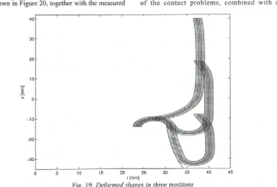
T he fib e r-re in fo rc e d ru b b e r co m p o site consists o f four layers, i.e., a rubber inner liner, a ru b b e r o u te r c o v e r a n d tw o h o m o g e n iz e d orthotropic fiber plies, which are oriented at angles o f ±45°. The thicknesses o f the rubber layers and the fiber plies are 1 mm and 0.5 mm, respectively. The inflation pressure is p — 4 b a r . The finite- element computations simulate the working process o f the air-spring. A ssum ing a constant inflation pressure the deform ations, stresses and resultant forces were determined in 19 positions.
Three deformed shapes, i.e., the 1st, 10th, 19th o f the airspring are shown in Figure 19.
T h e v e rtic a l d is p la c e m e n t v e rsu s the resultant force curve, i.e., the characteristic curve, is shown in Figure 20, together with the measured
values (see [31]). It is also clear that on the working area, i.e., 1 5 - 4 5 m m the calcu lated and the m e a su re d v a lu e s sh o w g o o d a g re e m e n t, so validating the proposed method.
Numerical examples showed that accurate global results, like the force-displacement curve, can also be obtained for low-order displacement polynomial degrees p = 1, 2. W hen a high-order approximation is used, i.e.,p = 2 ,3 ,4 , stress peaks may arise at the comers o f the polygon o f the contact border. H ow ever, at the o th er side w here the inflation pressure is exerted, the boundary condition is satisfied very accurately for the high-order displacement polynomial degrees p = 3, 4.
4 CONCLUSIONS
It is w ell know n that the stress state o f m a ch in e e le m e n ts is h ig h ly se n sitiv e to the g e o m e try n e a r th e stre s s p e a k s. T h is is a requirem ent to avoid stress peaks. The second section o f the article shows an effective method for acco m p lish in g it. N am ely, a sm ooth contact- pressure distribution can be achieved by using an appropriate control function on the controlled sub- domain.
H ighly accurate results m ay be realized using /»-extension finite elements for the solution o f th e c o n ta c t p ro b le m s , co m b in e d w ith a
E JE
N
r [mm]
Fig. 20. Characteristic curve o f the air-spring; solid line: numerical results, dots: measurements
positioning technique and special re-meshing. T h e p ro v id e d ex am p les d e m o n stra te th e effectiveness o f the proposed algorithms for the determ ination o f the initial shape, i.e., the initial gap, by observing the stress constraint. The method is also applicable for designing a clutch to maximize the transmissible torque.
The ap p lied o p tim izatio n p ro c e d u re is ap p licab le for designing highly loaded rollers, w hich are characterized by a smooth contact-stress distribution along the contact surfaces. Two types o f optimization problems were investigated. Firstly, the round-off (AL) is determined for a given force load (see Equation 30). Secondly, the force load is
c a lc u la ted fo r the p re sc rib e d ro u n d -o ff (see Equation 31). The maximum force load can also be determined with a modification of the round-off. The p -ex ten sio n finite elem ents are also very applicable for large-displacement problems when the contacting element’s edge is kept as a straight line. The global results are accurate enough at a low order o f approximations, i.e., the measured and calculated results show good agreement.
A cknow ledgm ent
The research is partially supported by the Hungarian Research Fund (OTKA T037759).
5 REFERENCES
[1] Hilding, D., Klarbring, A. and Petterson, J. (1999) Optimization o f structures in unilateral contact, ASME, Appi Mech. Rev., 52:(4) (1999), pp. 139-160.
[2] Haslinger, J. and Neittaanmaki, P. (1996) Finite element approximation for optimal shape design, John Wiley & Sons Ltd., London.
[3] Goryacheva, I.G. and Dobuchin, M.H. ( 1998), Contact problems in tribology, Mashinostroenie, Moscow. [4] Päczelt, I. (2000) Iterative Methods for solution o f contact optimization problems, Arch. Mech., 52:(4—
5) (2000), pp. 685-711.
[5] Päczelt, I. and Szabó, T. (2002) Solution o f contact optimization problems o f cylindrical bodies using the hp-FEM, International Journal fo r Numerical Methods in Engineering, 53:(1) (2002), pp. 123- 146.
[7] Szabó, B. and Babuška, I. (1991) Finite element analysis, Wiley-Intersience, New-York.
[8] Oh, K.P. and Trachmann, E.G. (1979) A numerical procedure for designing profiled rolling, ASME, Journal o f Lubrication Technology Series F, 101(1979), pp. 105-109.
[9] Harnett, M.J. (1979) The analysis o f contact stresses in rolling element bearings, ASME, Journal o f Lubrication Technology Series F, 101(1979), pp. 105-109.
[10] Trostenfelt, B. and Fredriksson, B. (1984) Pressure distribution in crowned roller contacts, Engineering Analysis, 1:(1) (1984), pp. 32-39.
[11] de Mul, J.M., Kalker J.J. and Frederiksson, B. (1986) The contact between arbitrary curved bodies of finite dimension, ASME, Journal o f Tribology, 108 (1986), pp. 140-148.
[12] Chiu, Y.P. and Harnett, M.J. (1987) A numerical solution for the contact problem involving bodies with cylindrical surface consireding cylindrical effect, ASME, Journal o f Tribology, 109(1987), pp. 479-486. [13] Pàczelt, I. and Szabó, T. (1994) Optimal shape design for contact problems, Structural Optimization,
7(1994), pp. 66-75.
[14] Kama, L. (2006) M odelling o f rollers in calculation o f hewing bearing w ith the use o f finite elements, Mechanism and Machine Theory, 41(2006), pp. 1359-1376.
[15] Krzeminski-Freda, H. and Warda, B. (1996) Correction o f the roller generators in spherical roller bearings, Wear, 192(1996), pp. 29-39.
[16] Park, T.J. and Kim, K.W. (1998) Elasthogydrodynamic lubrication o f a line contact, Wear, 223(1998), pp. 102-109.
[17] Lim, X. and Yang, P. (2002) Analysis o f the thermal elastohydrodynamic lubrication o f a finite line contact, Tribology Lnternational, 35(2002), pp. 137-144.
[18] Pàczelt, I. and Mróz, Z. (2005), On optimal contact shapes generated by wear process, International Journal fo r Numerical Methods in Engineering, 63 :(9) (2005), pp. 1250-1287.
[19] Wriggers, P. and M iehe, C. (1994) Contact constraints within thermo-mechanical analysis a finite element model, Computer Methods in Applied Mechanics and Engineering, 113(1994), pp. 301-319. [20] Podra, P. and A nderson, S. (1999) Sim ulating sliding w ear w ith finite elem ent m ethod, Tribol.
International, 32(1999), pp. 71-81.
[21] Pàczelt, I. and Pere, B. (1999) Investigation o f contact wearing problems with hp-version o f the finite element method, Thremal Stress ‘99, Skrzypek, J.J. and Hetnarski, R.B. (Eds), Crakow University of Technology, pp. 81-84.
[22] Crisfield, M.A. (1997) N on-linear finite element analysis o f solids and structures, John Wiley & Sons, New York.
[23] Wriggers, P. (2002) Computational contact mechanics, J. Wiley & Sons, New York.
[24] Pàczelt, L, Szabó, T. and Baksa, A. (2004) Product designing using finite element method and contact optimizations, Proceedings o f the TMCE2004, Lausanne, Switzerland, Horvàth & Xirouchakis (Eds), Millpress, Rotterdam, pp. 267-276.
[25] Archard, J.F. (1953) Contact and rubbing o f flat surfaces, Journal o f Applied Physics, 24(1953), pp. 981- 988.
[26] Bone, J. and Wood, R.D. ( 1997) Nonlinear continuum mechanics for finite element analysis, Cambridge University Press, Cambridge.
[27] Kalker, J.J. (1990) Three dimensional elastic bodies in rolling contact, Academic Publisher, Doordrecht. [28] Halpin, J.C. and Tsai, S.W. (1969) Effect o f environmental factors on composite materials, AFML-TR,
1969, pp. 67-423.
[29] Hartmann, S. and Neff, P. (2003) Polyconvexity o f generalized polynomial-type hyper elastic strain energy functions for near-incompressibility, International Journal fo r Solids and Structures, 40(2003), pp. 2767-2791.
[30] Stenberg, R. and Suri, M. (1996) M ixed hp finite elem ent methods for problems in elasticity and Stokes flow, Numer. Math., 72(1996), pp. 367-389.
Authors’ Address:
Prof. Dr. Istvän Päczelt Dr. Attila Baksa University o f Miskolc Department o f Mechanics
H-3515 Miskolc-Egyetemvaros, Hungary
Dr. Tamàs Szabó
Szechenyi Istvan University Department o f Applied Mechanics Egyetem ter 1
H-9028 Gyor, Hungary
Prejeto:
Received: 2.5.21 7
Sprejeto: ^ Odprto za diskusijo: 1 leto Accepted: ' ' Open for discussion: 1 year