Please cite this article as: A. R. Toloei, M. Zarchi, B. Attaran, Oscillation Control of Aircraft Shock Absorber Subsystem Using Intelligent Active Performance and Optimized Classical Techniques Under Sine Wave Runway Excitation, International Journal of Engineering (IJE), TRANSACTIONSB: Applications Vol. 29, No. 8, (August 2016) 1167-1174
International Journal of Engineering
J o u r n a l H o m e p a g e : w w w . i j e . i rOscillation Control of Aircraft Shock Absorber Subsystem Using Intelligent Active
Performance and Optimized Classical Techniques Under Sine Wave Runway
Excitation
A. R. Toloeia, M. Zarchi*a, B. Attaranb
a Department of Aerospace Engineering, University of ShahidBeheshti, Tehran, Iran b Department of Mechanical Engineering, University of Shahid Chamran, Ahwaz, Iran
P A P E R I N F O
Paper history: Received 25 April 2016
Received in revised form 20 June 2016 Accepted 14 July 2016
Keywords:
PID Classical Controller
Bees Intelligent Optimization Algorithm Hydraulic Nonlinear Actuator Active Performance Numerical Simulation
A B S T R A C T
This paper describes third aircraft model with 2 degrees of freedom. The aim of this study is to develop a mathematical model for investigation of adoptable landing gear vibration behavior and to design Proportional Integration Derivative (PID) classical techniques for control of active hydraulic nonlinear actuator. The parameters of controller and suspension system are adjusted according to bees optimization algorithm by minimizing body acceleration objective function. The results of numerical simulation indicates that the active landing gear system based on bees intelligent algorithm increases passengers and ride comfort and structure fatigue life by decreasing displacement, acceleration and load transmitted to airframe and shock absorber system significantly about 70% and 80% averagely compared to passive performance during touchdown phase with sine wave runway disturbance.
doi: 10.5829/idosi.ije.2016.29.08b.17
1. INTRODUCTION1
The dynamic load and vibration caused by the unevenness of runway will result in airframe fatigue and discomfort of passengers. The shock absorber system is supposed to control the impact load during the ground maneuver. If the aircraft moves on the road with high speed and under runway disturbance, that is considered a crash phenomenon, this outcome is inevitable with passive landing gear system because shock absorber quality is fixed in various conditions. In active approach, flow rate of hydraulic liquid is controllable. Therefore, the concentrate on active performance is unavoidable to overpower the difficulties in passive system. In recent years, the active control began to be popular and widely used in vibration control of constructions and suspensions.
The benefit of bees algorithm is used by Ghanbarzadeh et al. [1-5] in a variety of functions. The
1*Corresponding Author’s Email: [email protected] (M.
Zarchi)
benefits of this active system in decreasing touchdown forces and oscillations caused by disturbances was deduced by Lucas [6] by analysis and experimentation. Payne et al. [7] implemented a mathematical model with nonlinear characteristics for main landing gear improved with an external hydraulic system. The work performed by Jocelyn [8] has been investigated on landing gears with active control for a range of airplane speeds and for various runway surfaces.
Attaran et al. [9] indicated good performance of active suspension system at landing impact and designed PID based on BA controller that chooses shock absorbing force of system as object function.
The most aircraft utilize landing gears with passive performance which are designed by the producers [10]. Some researchers [11-13] demonstrated that the advantages of utilizing control force to the suspension system to restrict the impact forces induced to the fuselage. Ross and Edson [14] introduced controllable landing gear system for the first time. The benefits of this active system in decreasing touchdown forces and oscillations caused by disturbances was deduced by
TECHNICAL NOTE
Freymann [15-17] by analysis and experimentation. The work performed by Catt [18] has been investigated on landing gears with active control for a range of airplane speeds and for various runway surfaces.
Horta et al. [6] implemented a mathematical model with nonlinear characteristics for main landing gear improved with an external hydraulic system. A6 intruder landing gear system has been surveyed based on analysis and test method [19]. NASA researchers [20] survied the behavior of nose shock strut using F-106B airplane. This study concentrated on observation and experimental data based on drop tests and deduced that the active landing gear system significantly increases aircraft structure fatigue life during ground maneuvers. Wang et al. [21] investigated a mathematical model of two degrees of freedom for A6 intruder with single active landing gear system and pointed improvement of shock absorber performance with proportional integral derivative controller that gains are optimized through numerical simulation experiments. According to studies of [22] for automotive applications, compared with the passive control, the active control has fantabulous tunability.
Sivakumar et al. [23] analyzed aircraft vibration due to runway irregularities with PID controller which coefficients are tuned by Ziegler-Nichols method. In reference [24], Zarchi et al. designed LQR controller for full aircraft model in order to analyze vibrational model. In this paper, the mathematical model with two masses and 2 degrees of freedom for third aircraft model with active landing gear is developed. In the second step, PID controllers with tuning method on the basis of bees optimization algorithm is described. In the next step, the comparison is made between the active and passive performances in touchdown phase with body acceleration objective function by numerical simulation. The final step is a short discussion and conclusion on the basis of results from previous step.
2. MECHANICAL MODEL of ACTIVE ADOPTABLE LANDING GEAR SYSTEM
The oleo-pneumatic landing gear includes the airframe, cylinder, the piston and wheel. Active shock absorber system is equipped by active control unit with lower and upper chambers that are connected by a small orifice. This combination betters the performance of the suspension system compared to passive approach by modifying quantity of oil flow. Mechanical model of passive and active airplane and landing gear is shown in Figure 1.
Figure 1. mechanical model of passive and active system
3. MATHEMATICAL MODEL of ACTIVE
ADOPTABLE LANDING GEAR SYSTEM
Mathematical model of the system and vibration equations according to Figure 1 are mentioned as:
3.1. Dynamic Equilibrium Equations of Active Landing Gear System
1 1 1
2 2 2
c k
c k
m y m g L F F FQ
m y m g Ft F F FQ
(1)
3. 2. Damping Force
)
1( 1 2
c
F c y y (2)
3. 3. Spring Force
)
1( 1 2
k
F k y y (3)
3. 4. Active Control Force
2 sgn(Q) FQ k Qa k Qb
psh psl Q C wxQ
3. 5. Tyre Force
2( 2 ) 2( 2 )
Ft c y y k y y
g g
(5)
4. PID CONTROLLER
One of the PID controllers tuning methods is open loop technique based on minimum error integral criteria. Before proceeding with a brief discussion of this method, it is important to note that the PID controllers transfer function is defined by:
( ) i
p d
k
G s k k s
s
(6)
where, above tunable parameters can be adapted by this method to gain the best control efficiency. The active control force caused by suspension system and control law for improvement of landing gear system performance is defined according toWang et al. [21].
5. BEES OPTIMIZATION ALGORITHM
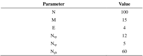
This intelligent algorithm is applied for tuning of PID classical controller parameters according to [1, 4]. In this paper, this algorithm is implemented by using integral of the time weighted absolute value of the error (ITAE) according to Equation (7) as objective function. ITAE is applied to achieve acceptable stability and medium fastness of response for the control system due to existence of time and error in this function. Bees algorithm parameters and control gains for optimization of PID controller and suspension system with body acceleration objective function for ITAE are obtained in Tables 1 to 4. The stability conditions as adjustable parameters of the controller to utilize in bees algorithm is presented according to Equation (8).
( ) . 0
ITAE t e t dt (7)
0.01 10 0.1 1000 0.00001 1 p i d k k k (8)
TABLE 1. Bees algorithm parameters for PID optimization
Parameter Value
N 100
M 15
E 4
Nep 12
Nsp 5
Ngh 60
TABLE 2. Control gains for PID optimization
Type of controller kp ki kd
Passive 0 0 0
PID-Bees Algorithm 0.652985 2.653764 0.052654
TABLE 3. Bees algorithm parameters for suspension system optimization
Parameter Value
N 150
M 20
E 5
Nep 15
Nsp 10
Ngh 40
TABLE 4. Control gains for suspension system optimization
Type of controller kp ki kd
Passive 0 0 0
PID-Bees Algorithm 0.4676492 674.3761 0.07646142
6. NUMERICAL SIMULATION
Fokker airplane is investigated in control system simulation software as case study. Aircraft and Landing gear masses 22000 kg and 650 kg, respectively [23]. The model parameters have been obtained according to Table 5. The dynamic responses for third aircraft model by using numerical simulation in MATLAB Simulink environment are acquired. Profile of sine wave runway excitation in touchdown phase according Equation (9) is given.
0.1(1 cos 7.85 )0 0.4
yg t t (9)
6. 1. Active System with Classical Techniques
Optimization In this part, numerical simulation is
obtained based on two control performances. passive control and PID techniques based on bees Algorithm for active system.
TABLE 5. Data used in the simulation
Description Value
c1 (Ns/m) 13.93e5
k1 (N/m) 14.89e5
c2 (Ns/m) 12198
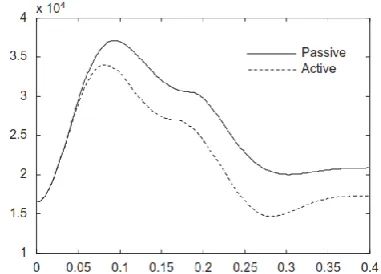
Figures 2-9 show that the parameters of suspension displacement and load induced to fuselage consist of all forces of shock strut subsystem with acceleration objective function for optimizataion are reduced significantly using PID-BA technique compared to passive performance.
Figure 2. The suspension force with P controller optimization
Figure 3. The suspension displacement with P controller optimization
Figure 4. The suspension force with PD controller optimization
Figure 5. The suspension displacement with PD controller optimization
Figure 6. The suspension force with PI controller optimization
Figure 7. The suspension displacement with PI controller optimization
Figure 9. The suspension displacement with PID controller optimization
Table 6 is a comparison between passive and Bees Algorithm method for evaluation of active suspension system with PID classical techniques.
The summarized results of Table 6 demonstrates that improvement percentage of PID-BA active system compared to passive performance is about 66% and 62% for displacement and force, respectively which leads to comfort of ride and passengers and betterment of structure life.
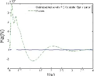
As validation, numerical results for the suspension force is verified by Figure 10 concerned to reference [21] that performance of active landing gear is improved using PID technique based on numerical simulation experiments. Difference between peak points of them is due to different sink speeds and runway excitations but the curves are the same. The improvement percentage of PID-BA active system compared to passive and active performance according to Wang et al. [21] is about 77% and 70% for shock absorber force, respectively.
6. 2. Intelligent Active System with Classical
Techniques Optimization In this section, the
process of simulation is performed for two control techniques including, passive control and PID method on the foundation of Bees optimization Algorithm for active system.
TABLE 6. Comparison of time responses
Performance Overshoot (m) Force (N)
Passive 1.11429 98333.3
P-BA 0.836795 89166.7
PD-BA 0.371429 37083.3
PI-BA 0.660534 82916.7
PID-BA 0.371429 37083.3
Percentage 66% 62%
Figures 11-16 show that the parameters of displacement and impact force related to fuselage and landing gear are reduced importantly with acceleration objective function for optimizataion using PID-BA technique and intelligent suspension subsystem accordance to bees algorithm have good improvement percentage compared to passive performance.
Figure 10. The suspension force with PID controller based on numerical simulation experiments [21]
Figure 11. The intelligent suspension displacement with P controller optimization
Figure 13. The intelligent suspension displacement with PD controller optimization
Figure 14. The intelligent suspension displacement with PI controller optimization
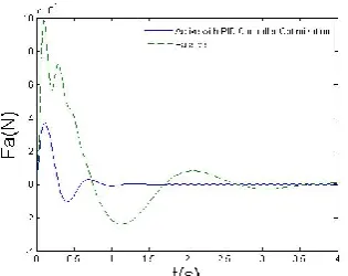
Figure 15. The intelligent suspension force with PID controller optimization
Figure 16. The intelligent suspension displacement with PID controller optimization
Table 7 is a comparison between passive and Bees algorithm method for evaluation of intelligent active suspension system with PID classical techniques. According to Table 7, the shock absorber displacement and impact load decreased 82% and 99% by using Bees algorithm compared to passive method that results in improvement structure fatigue life and passengers comfort. Moreover, reducing these parameters leads to betterment ride comfort and making better body and landing gear structure life.
As validation, numerical results for the suspension displacement is verified by Figure 17 concerned to reference [23] that performance of active landing gear is improved using PID technique based on Ziegler-Nichols. Difference between peak points of them is due to different sink speeds and runway excitations but the curves are the same.The improvement percentage of PID-BA intelligent active system compared to passive and active performance according to [23] is about 87% and 75% for suspension displacement , respectively.
TABLE 7. Comparison of time responses
Performance Overshoot (m) Force (N)
Passive 1.1092 95833.3
P-BA 0.452381 -
PD-BA 0.338095 17083.3
PI-BA 0.471429 -
PID-BA 0.195238 833.333
Percentage 82% 99%
Figure 17. The suspension displacement with PID controller based on Ziegler-Nichols [23]
7. CONCLUSION AND DISCUSSION
good compromise in dynamic responses of third aircraft model for the control system. It can be demonstrated that improvement of displacements, accelerations and loads results in betterment of the active landing gear efficiency with bees intelligent algorithm based on minimum error criteria method by minimizing body acceleration objective function related to model as optimization problem compared with passive system. This paper shows that the important advantage of Bees algorithm is good robustness and stability of PID technique optimized performance for active system versus unintelligent and intelligent shock absorber subsystem. For the next research, investigation of the competence for this type of aircraft with more complete model due to type of maneuver ground and runway profile, other active nonlinear actuator and semi-active performance of landing gear system will study and PID controller will be adjusted with other optimization algorithms.
8. REFERENCES
1. Pham, D., Ghanbarzadeh, A., Koc, E., Otri, S., Rahim, S. and Zaidi, M., "The bees algorithm–a novel tool for complex optimisation", in Intelligent Production Machines and Systems-2nd I* PROMS Virtual International Conference (3-14 July 2006). (2011).
2. Pham, D., Ghanbarzadeh, A., Koc, E. and Otri, S., "Application of the bees algorithm to the training of radial basis function networks for control chart pattern recognition", in Proceedings of 5th CIRP international seminar on intelligent computation in manufacturing engineering (CIRP ICME’06), Ischia, Italy, (2006), 711-716.
3. Pham, D., Otri, S., Ghanbarzadeh, A. and Koc, E., "Application of the bees algorithm to the training of learning vector quantisation networks for control chart pattern recognition", in 2006 2nd International Conference on Information & Communication Technologies, IEEE. Vol. 1, (2006), 1624-1629. 4. Pham, D., Koç, E. and Ghanbarzadeh, A., "Optimization of the weights of multi-layered perceptions using the bees algorithm, Proceedings Of International Symposium On Intelligent Manufacturing Systems., (2006).
5. Pham, D., Castellani, M. and Ghanbarzadeh, A., "Preliminary design using the bees algorithm", in Proceedings of eighth international conference on laser metrology, CMM and machine tool performance, LAMDAMAP, Euspen, Cardiff, UK., (2007), 420-429.
6. Horta, L.G., Daugherty, R.H. and Martinson, V.J., "Modeling and validation of a navy a6-intruder actively controlled landing gear system", (1999).
7. Payne, B., Dudman, A., Morris, B. and Hockenhull, M.,
"Aircraft dynamic response to damaged and repaired runways",
AGARD CP-326, (1982).
8. Jocelyn, I., "An overview of landing gear dynamics", Vol., No., (1999).
9. Toloei, A.R., Zarchi, M. and Attaran, B., "Application of active suspension system to reduce aircraft vibration using pid technique and bees algorithm", International Journal of Computer Applications, Vol. 98, No. 6, (2014).
10. Currey, N.S., "Aircraft landing gear design: Principles and practices, Aiaa, (1988).
11. Wignot, J., Durup, P. and Gamon, M., "Design formulation and analysis of an active landing gear", Vol. I Analysis, AFFDL-TR-71-80, Vol. 1, (1971).
12. Bender, E., Berkman, E. and Bieber, M., "A feasibility study of active landing gear", Affdl-tr-70-126, US Air Force, (1971). 13. McGehee, J.R. and Carden, H.D., Analytical investigation of the
landing dynamics of a large airplane with a load-control system in the main landing gear. 1979, DTIC Document.
14. Ross, I. and Edson, R., "Application of active control landing gear technology to the a-10 aircraft", (1983).
15. Freymann, R. and Johnson, W.P., "Simulation of aircraft taxi testing on the agile shaker test facility", in DGLR The 2 nd International Symposium on Aeroelasticity and Structural Dynamics (SEE N 86-30627 22-01)., (1985), 468-476
16. Freymann, R., "An experimental-analytical routine for the dynamic qualification of aircraft operating on rough runway surfaces", AGARD R-731, (1987).
17. Freymann, I.R., "Actively damped landing gear system", AD-A239 914, (1991).
18. Catt, T., Cowling, D. and Shepherd, A., "Active landing gear control for improved ride quality during ground roll", Smart Structures for Aircraft and Spacecraft (AGARD CP 531), Stirling Dynamics Ltd, Bristol, (1993).
19. Daniels, J.N., "A method for landing gear modeling and simulation with experimental validation", (1996).
20. Howell, W., McGehee, J., Daugherty, R. and Vogler, W., "F-106b airplane active control landing drop test performance", in Landing Gear Design Loads Conference No. 21, AGARD Conference Proceedings. Vol. 484, (1991), 8-12.
21. Wang, H., Xing, J., Price, W. and Li, W., "An investigation of an active landing gear system to reduce aircraft vibrations caused by landing impacts and runway excitations", Journal of Sound and vibration, Vol. 317, No. 1, (2008), 50-66.
22. Karnopp, D., "Active damping in road vehicle suspension systems", Vehicle System Dynamics, Vol. 12, No. 6, (1983), 291-311.
23. Sivakumar, S. and Haran, A., "Mathematical model and vibration analysis of aircraft with active landing gears", Journal of Vibration and Control, Vol. 21, No. 2, (2015), 229-245. 24. Toloei, A., Aghamirbaha, E. and Zarchi, M., "Mathematical
model and vibration analysis of aircraft with active landing gear system using linear quadratic regulator technique",
Oscillation Control of Aircraft Shock Absorber Subsystem Using
Intelligent Active Performance and Optimized Classical Techniques
Under Sine Wave Runway Excitation
TECHNICAL NOTE
A. R. Toloeia, M. Zarchia, B. Attaranb
a Department of Aerospace Engineering, University of ShahidBeheshti, Tehran, Iran b Department of Mechanical Engineering, University of Shahid Chamran, Ahwaz, Iran
P A P E R I N F O
Paper history: Received 25 April 2016
Received in revised form 20 June 2016 Accepted 14 July 2016
Keywords:
PID Classical Controller
Bees Intelligent Optimization Algorithm Hydraulic Nonlinear Actuator Active Performance Numerical Simulation
هديكچ
يسزسب ياسب يضايز لده كي طسب ِلاقه ييا فدّ .دٌك يه فيصَت از يداشآ ِجزد ٍد اب اويپاَّ مَس كي لده ِلاقه ييا يطخسيغ سگلوع لستٌك ياسب يقتطه يلاسگتًا يبساٌت كيسلاك ياْكيٌكت يحاسط ٍ سيرپ قيبطت دٍسف ِبازا يضاعتزا زاتفز اب لسعزَبًش يشاس ٌِيْب نتيزَگلا قبط سب قيلعت نتسيس ٍ سلستٌك ياّستهازاپ .تسا ُدض ِتفسگ سظً زد لاعف يكيلٍزديّ سب لاعف دٍسف ِبازا نتسيس ِك دّد يه ىاطً يددع يشاس ِيبض جياتً .ددسگ يه نيظٌت ًِدب باتض فدّ عبات ىدسك مَويٌيه َس يتحاز لسع زَبًش دٌوضَّ نتيزَگلا ياٌبه باتض ٍ يياجباج ىداد صّاك اب از ُشاس يگتسخ سوع صيً ٍ ىاسفاسه ٍ يزا
دٍدح يسيگوطچ زَطب ِبسض بذاج نتسيس ٍ ُشاس ِب ِتفاي لاقتًا زاب ييٌچوّ ٍ ًِدب 07
ٍ % 07 ِسياقه زد ييگًايه زَطب %
.دّد يه صياصفا يسٌَيس جَه دٍسف دًاب شاطتغا اب تسطً شاف لَط زد لاعفسيغ دسكلوع اب