5
Information Technology and Control 2017/1/46
Proper Augmented
Marked Graphs: Properties,
Characterizations and Applications
ITC 1/46
Journal of Information Technology and Control
Vol. 46 / No. 1 / 2017 pp. 5-15
DOI 10.5755/j01.itc.46.1.13970 © Kaunas University of Technology
Proper Augmented Marked Graphs: Properties, Characterizations and Applications
Received 2017/01/13 Accepted after revision 2016/02/17
http://dx.doi.org/10.5755/j01.itc.46.1.13970
Corresponding author: [email protected]
King Sing Cheung
The Open University of Hong Kong, 30 Good Shepherd Street, Homantin, Kowloon, Hong Kong
Augmented marked graphs possess a special structure for modelling distributed systems with shared resourc-es. Not only inheriting the desirable properties of augmented marked graphs such as on liveness and revers-ibility, proper augmented marked graphs also exhibit other desirable properties, including boundedness and conservativeness. However, proper augmented marked graphs have a rather complicated definition that inev-itably undermines the usability in system modelling. In this paper, based on composition of live and bounded marked graphs, new characterizations for proper augmented marked graphs are devised. Through these char-acterizations, proper augmented marked graphs can be effectively used in modelling and analyzing conflicting processes of a distributed system. Applications to distributed transaction processing with shared resources are discussed.
KEYWORDS: Petri nets, marked graphs, augmented marked graphs, proper augmented marked graphs, distri- buted systems, shared-resource systems, component based systems, distributed transaction processing, sys-tems integration.
Introduction
A subclass of Petri nets, augmented marked graph was first introduced by Chu and Xie for modelling systems with shared resources [1]. In the literature, thorough investigation on augmented marked graphs was mainly conducted by Cheung [2-6]. Having a spe-cial structure for representing shared resources,
where a cycle-inclusion property was used for char-acterizing the liveness and reversibility [2, 3]. Trans-formation-based characterizations for bounded and conservative augmented marked graphs were intro-duced [4, 6]. There are also studies on the composi-tion of augmented marked graphs and its applicacomposi-tions to system integration [7-11].
Proper augmented marked graphs are a special type of augmented marked graphs, found by Cheung [6, 12]. Not only inheriting all the properties of augment-ed markaugment-ed graphs, proper augmentaugment-ed markaugment-ed graphs also possess more properties, including bounded-ness and conservativebounded-ness. However, like augment-ed markaugment-ed graphs, proper augmentaugment-ed markaugment-ed graphs have a rather complicated definition, thus adding difficulties in system modelling and analysis. This dilemma can be resolved by some characterizations of proper augmented marked graphs. In this paper, based on the composition of live and bounded marked graphs, a number of characterizations are proposed. With these characterizations, the processes or com-ponents of a system can be readily modelled as marked graphs, and then composed via their common resource places. The integrated PT-net so obtained is a proper augmented marked graph which represents the integrated whole of the processes or components. In a distributed system, it is often that two or more concurrent processes compete for some shared re-sources. Owing to the existence of these conflicting processes, erroneous situations such as deadlock and capacity overflow may occur. In this paper, it is pro-posed to model the conflicting processes as marked graphs, and then, to compose them as a proper aug-mented graph which represents the integrated whole of the processes for analysis.
The rest of this paper is structured as follows. Sec-tion 2 states the definiSec-tions and properties of proper augmented marked graphs. New characterizations are proposed in Section 3. Section 4 then shows the modelling and analysis of conflicting processes using proper augmented marked graphs and their proper-ties and characterizations. Section 5 describes the application to the analysis of distributed transaction processing systems with common shared resources, and illustrates with examples. Section 6 briefly con-cludes this paper. It is noted that readers are assumed to have basic knowledge on Petri nets [13-15].
Proper augmented marked
graphs and their properties
Proper augmented marked graphs are a special type of augmented marked graphs [6, 12]. The definitions and known properties are summarized below.
Definition 1. An augmented marked graph (N, M0; R)
is a PT-net (N, M0) with a specific subset of places R
(called resource places), satisfying the following con-ditions: (a) Every place in R is marked by M0. (b) The
PT-net (N‘, M0) obtained from (N, M0; R) by removing
the places in R and their associated arcs is a marked graph. (c) For each r∈ R, there exist kr > 1 pairs of
tran-sitions Dr = { 〈ts1, th1〉, 〈ts2, th2〉, …, 〈tskr, thkr〉 } such that r• = { ts1, ts2, ..., tskr } ⊆ T and •r = { th1, th2, ..., thkr } ⊆ T and that,
for each 〈tsi, thi〉 ∈Dr, there exists in N‘ an elementary
path ρri connecting tsi to thi. (d) In (N‘, M0‘), every cycle
is marked and no ρri is marked.
Definition 2. Let (N, M0; R) be an augmented marked
graph to be transformed into a PT-net (N‘, M0‘) as
fol-lows. For each place r ∈ R, where Dr = { 〈ts1, th1〉, 〈ts2, th2〉, …, 〈tskr, thkr〉 }, r is replaced by a set of places Q = { q1, q2, …, qkr }, such that M0‘[qi] = M0[r], qi• = { tsi } and •qi = { thi }. (N‘, M0‘) is called the R-transform of (N, M0; R). Definition 3. Let (N, M0; R) be an augmented marked
graph, and (N‘, M0‘) be the R-transform of (N, M0; R). (N, M0; R) is a proper augmented marked graph if and
only if every place in (N‘, M0‘) belongs to a cycle.
Figure 1
A proper augmented marked graph
t3
r2
t4
p5
t5
p6
r3
t8
t9
p9
t10
p10
p2 p12
p4
t1
t2
p3
p1
p8
t7
p7 p11
r1
7
Information Technology and Control 2017/1/46
Property 1. A proper augmented marked graph (N, M0; R) is live and reversible if and only if every R-siphon would never become empty [6, 12]. (Note : A R-siphon is a minimal siphon which contains at least one place in R.)
Property 2. A proper augmented marked graph is
bounded and conservative [6, 12].
Figure 1 shows a proper augmented marked graph (N, M0; R), where R = { r1, r2, r3 }. (N, M0; R) is bounded and
conservative. However, it is neither live nor revers-ible since there exists a R-siphon { r2, r3, p6, p10 }, which
would become empty on firing 〈 t1, t2, t3, t8 〉.
Characterizations for proper
augmented marked graphs
Based on the composition of live and bounded marked graphs, in the following, a number of new characteri-zations for proper augmented marked graphs are pro-posed.
Definition 4. Let (N1, M10), (N2, M20), …, (Nn, Mn0) be
PT-nets. Suppose Q = { p1, p2, …, pk } is a set of places
that are common to the PT-nets, where p1, p2, …, pk are
marked. By fusing p1, p2, …, pk into one single marked
place q, the resulting net (N, M0) is called the
integrat-ed PT-net obtainintegrat-ed by composing (N1, M10), (N2, M20), …, (Nn, Mn0) via the set of common places Q.
Proposition 1.Let (N, M0; R) be a proper augmented marked graph, and (N’, M0’) be the R-transform of (N, M0; R). (N’, M0’) is structurally the composite PT-net of a set of disconnected, live and bounded marked graphs. Proof. Consider the transformation of (N, M0; R) into (N’, M0’), as described in Definition 2. Let R = { r1, r2, …, rn }. Each ri ∈ R is replaced by a set of marked places Qi, for i = 1, 2, …, n. For any place p in (N’, M0’), | •p | = | p• | = 1. Let g be a cycle in (N’, M
0’). There are two
possi-ble cases for g. In case g contains any place in Q1∪ Q2∪ … ∪ Qn, g is marked. In case g does not contain any place
in Q1 ∪ Q2 ∪ … ∪ Qn, g also exists in (N, M0; R). According
to Cheung, every cycle in an augmented marked graph is marked [1, 2, 6]. Hence, g is also marked. Then, for
(N’, M0’), every place belongs to a cycle and every
cy-cle is marked, thus fulfilling the conditions of live and bounded marked graphs. (N’, M0’) is structurally a live
and bounded marked graph or a composite of a set of live and bounded marked graphs.
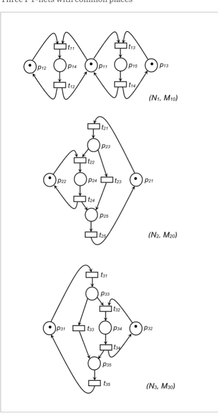
Figure 2 shows three PT-nets, (N1, M10), (N2, M20) and
(N3, M30). Suppose they have some common places, Q1 = { p11, p21, p31 }, Q2 = { p12, p22 } and Q3 = { p13, q32 }.
Fig-ure 3 shows the integrated PT-net (N, M0) obtained by
composing (N1, M10), (N2, M20) and (N3, M30) via Q1, Q2
and Q3, where q1, q2and q3 are the fused common
plac-es, respectively.
Proposition 2. A proper augmented marked graph (N, M0; R) is the integrated PT-net obtained after
compos-ing a set of live and bounded marked graphs via their common places, where R is the set of fused places.
Proof. It follows from Proposition 1. For any place p
Figure 2
Three PT-nets with common places
t34
t32
t24
p24
t22
p22
t14
p15
t13
p11
t12
p14
t11
p12
p23
t21
t25
p13
p21
t23
p34
p31
p33
t31
t35
p35
p32
t33
p25
(N3, M30)
(N1, M10)
not involved in the fusing, | •p | = | p• | = 1. For any place r
involved in the fusing, | •r | = | r• | = k. R is the set of fused
places.
Proposition 2 offers a more concise definition for proper augmented marked graphs. It can be effective-ly used in characterizing the boundedness and con-servativeness of proper augmented marked graphs, as well as the property-preserving composition of prop-er augmented marked graphs.
Lemma 1. Let N = 〈 P, T, F 〉 be a PT-net, N’ = 〈 P’, T’, F’ 〉 be the PT-net obtained from N after fusing a set of places Q = { q1, q2, ..., qn } ⊆ P into one single place r ∈ P’. If there exists a place invariant a of N such that a[q1] = a[q2] = ... = a[qn] = k ≥ 0, then there also exists a place invariant a’ of N’ such that a’[r] = k and a’[s] = a[s] for any s ∈ P’ \ { r } = P \ Q.
Proof. Since N’ is obtained from N by fusing Q = { q1, q2, ..., qn } into r, we have P’ = ( P \ Q ) ∪ { r }. Let V be the
in-cidence matrix of N. Then, the incidence matrix V’ of N’
satisfies that V’[r] =Σi=1,2,...,n V[qi] and V’[s] = V[s] for any s ∈ P’ \ { r } = P \ Q. Since a is a place invariant of N, aV
= 0. Let a’ be a place vector of N’ such that a’[r] = a[q1] = a[q2] = ... = a[qn] = k and a’[s] = a[s] for every s ∈ P’ \ { r } = P \ Q. Then, a’V’ = a’[r]V’[r] + Σp∈(P’\{r}) a’[p]V’[p] = Σi=1,2,...,n a[qi]V[qi] + Σp∈(P\Q) a[p]V[p] = aV = 0. Hence, a’ is
a place invariant of N’.
Proposition 3.A proper augmented marked graph is
bounded and conservative.
Proof. According to Proposition 2, a proper augmen-
Figure 3
The integrated PT-net obtained by composing the PT-nets in Figure 2 via their common places
t23
t34
t32
t24
p24
t22
t14
p15
t13
q1
t12
p14
t11
q2
p23
t25
p25
q3 p34
p33
t31
t35
p35
t33
t21
ted marked graph (N, M0; R) is an integrated PT-net
obtained after composing a set of live and bounded marked graphs { (N1, M10), (N2, M20), …, (N, Mk0) } by
fus-ing some marked places. Let (N’, M0’) be the composite
PT-net of (N1, M10), (N2, M20), …, (N, Mk0). Since each (Ni, Mi0) is bounded, there exists a place invariant a’ in (N’, M0’) such that a’ = k > 0. According to Lemma 1, there
also exists a place invariant a in (N, M0; R) such that a = k > 0. Hence, (N, M0; R) is bounded and conservative.
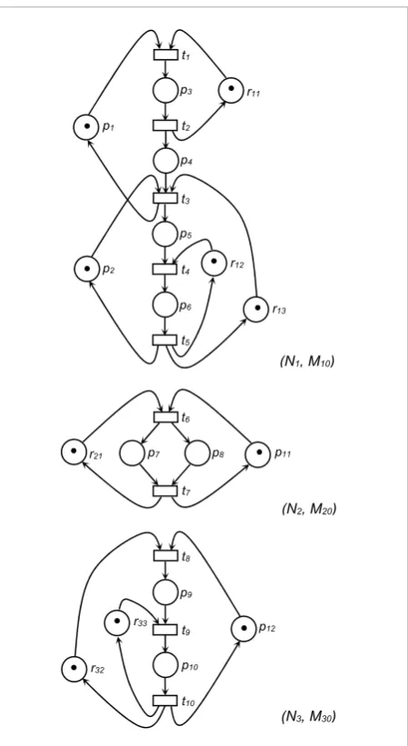
Proposition 4. The integrated PT-net obtained by
composing a set of live and bounded marked graphs via their common places is a proper augmented marked
Figure 4
A set of live and bounded marked graphs
r12 t3
t4 p5
t5 p6
r33 t8
t9 p9
t10 p10 p2
p12 p4
t1
t2 p3
p1
p8
t7
p7 p11
r11
t6
r21
r32
r13
(N1, M10)
(N2, M20)
9
Information Technology and Control 2017/1/46
graph (N, M0; R), where R is the set of fused places. Proof. It directly follows from Propositions 2 and 3. Figure 4 shows a set of live and bounded marked graphs { (N1, M10), (N2, M20), (N3, M30) }. They are
com-posed by fusing r11 and r21 into one single place r1, r12
and r32 into r2, and r13 and r33 into r3. The resulting
PT-net is a proper augmented marked graph (N, M0; R),
where R = { r1, r2, r3 }, as shown in Figure 1.
Modelling and analysis
of conflicting processes
This section discusses how proper augmented marked graphs can be effectively used in the model-ling and analysis of conflicting processes.
Typically in a distributed system, a number of con-current processes compete for some shared resour-ces. Erroneous situations occur when two or more processes are each waiting for the other to finish and neither ever does. The processes will continue to wait endlessly, resulting into deadlocks. There are also erroneous situations where resources exceed their capacity limits, thus causing capacity overflow. These processes are called conflicting processes.
In system integration, especially for distributed systems with concurrent processes competing for shared resources, one difficult challenge is to identify any erroneous situations such as deadlock and capac-ity overflow. This can be approached by using proper augmented marked graphs and their properties and characterizations. Consider a set of conflicting pro-cesses, competing for shared resources R = { r1, r2, ..., rk }. Steps for modelling and analysis are outlined
be-low.
Step 1. Model each process as a marked graph (Ni, Mi0), where any shared resource to be used is
repre-sented as a marked place called resource place. For a total of n processes, we have a set of marked graphs
{ (N1, M10), (N2, M20), ..., (Nn, Mn0) }.
Step 2. Check if each (Ni, Mi0) is live and bounded. (Ni, Mi0) is live and bounded if and only if every place in
belongs to a cycle and every cycle is marked [16].
Step 3. Suppose (N1, M10), (N2, M20), ..., (Nn, Mn0) are
live and bounded. Compose them via their common
resource places. According to Proposition 2, the in-tegrated PT-net is a proper augmented marked graph
(N, M0; R), where R = { r1, r2, ...,rk } denotes the shared
resources.
Step 4. Analyze the properties of (N, M0; R), which
represents an integration of the conflicting process-es. According to Property 2, (N, M0; R) is bounded and
conservative. Based on Property 1, (N, M0; R) is live
and reversible if and only if every R-siphon would nev-er become empty.
Suppose there is a distributed system with shared resources r1, r2 and r3, where r1 is shared by
process-es C1 and C2, and r2 and r3 are shared by
process-es C1 and C3. As shown in Figure 4, C1, C2 and C3 are
modelled as live and bounded marked graphs (N1, M10), (N2, M20) and (N3, M30), respectively. Referring
to the same resource, r11 in (N1, M10) and r12 in (N2, M20) are fused as one single place r1. Likewise, r12 in (N1, M10) and r32 in (N3, M30) are fused as r2, and r13 in (N1, M10) and r33 in (N3, M30) are fused as r3.
Accord-ing to Proposition 4, the integrated PT-net is a prop-er augmented marked graph (N, M0; R), where R = { r1, r2, r3 }, as shown in Figure 1.
Application to distributed
transaction processing
situ-ations would never occur. Hence, it is one of the de-sign objectives to verify if a system is live, that is, free from deadlock situations. Proper augmented marked graphs can be effectively applied to solve this problem by following the steps described in Section 4.
Example 1. Consider a typical distributed transac-tion processing system which involves a number of concurrent processes, accessing some common data objects. Among other processes, there are 3 concurrent processes each needs to access 2 common data objects (namely, O1 and O2) in processing some
transactions. A functional description of the proces-ses is as follows.
Process 1. At its initial state, the process intends to access O1. Once O1 is available, it is locked to prevent
accesses from other processes. The process enters to
a state, intending to access O2. Once O2 is available,
it is locked by the process too. Update transactions on both O1 and O2 are then processed. After finishing
these update transactions, the process releases O2.
There are some further update transactions on O1,
af-ter which O1 is released.
Process 2. At its initial state, the process intends to access O2. Once O2 is available, it is locked to prevent
accesses from other processes. The process enters to a state, intending to access O1. Once O1 is available, it
is locked by the process too. Update transactions on both O1 and O2 are then processed. After finishing these
update transactions, the process releases O1. There are
some further update transactions on O2, after which O2
is released.
Process 3. At its initial state, the process intends to
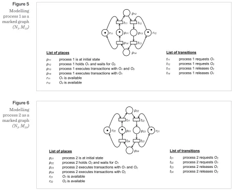
Figure 5
Modelling process 1 as a marked graph
(N1, M10)
List of places
p11 process 1 is at initial state
p12 process 1 holds O1 and waits for O2
p13 process 1 executes transactions with O1 and O2
p14 process 1 executes transactions with O1
r11 O1 is available
r12 O2 is available
List of transitions t11 process 1 requests O1
t12 process 1 requests O2
t13 process 1 releases O2
t14 process 1 releases O1
p12
t12
t11
t13
r11 p11 p13 r12
p14
p14
Figure 6
Modelling process 2 as a marked graph
(N2, M20)
List of places
p21 process 2 is at initial state p22 process 2 holds O2 and waits for O1
p23 process 2 executes transactions with O1 and O2 p24 process 2 executes transactions with O2 r21 O1 is available
r22 O2 is available
List of transitions
t21 process 2 requests O2 t22 process 2 requests O1 t23 process 2 releases O1 t24 process 2 releases O2 p22
t22 t21
p23
t23 r21 r22 p21
p24 t24
List of places
p21 process 2 is at initial state p22 process 2 holds O2 and waits for O1
p23 process 2 executes transactions with O1 and O2 p24 process 2 executes transactions with O2 r21 O1 is available
r22 O2 is available
List of transitions
t21 process 2 requests O2 t22 process 2 requests O1 t23 process 2 releases O1 t24 process 2 releases O2 p22
t22 t21
p23
t23 r21 r22 p21
11
Information Technology and Control 2017/1/46
Figure 7
Modelling process 3 as a marked graph
(N3, M30)
List of places
p31 process 3 is at initial state
p32 process 3 executes transactions with O1 and O2
r31 O1 is available
r32 O2 is available
List of transitions
t31 process 3 requests O1 and O2
t32 process 3 releases O1 and O2
t31
p32 r32
r31 p31
t32
List of places
p31 process 3 is at initial state
p32 process 3 executes transactions with O1 and O2
r31 O1 is available
r32 O2 is available
List of transitions
t31 process 3 requests O1 and O2
t32 process 3 releases O1 and O2
t31
p32 r32
r31 p31
t32
List of places
p31 process 3 is at initial state
p32 process 3 executes transactions with O1 and O2
r31 O1 is available
r32 O2 is available
List of transitions
t31 process 3 requests O1 and O2
t32 process 3 releases O1 and O2
t31
p32 r32
r31 p31
t32
List of places
p11 process 1 is at initial state
p12 process 1 holds O1 and waits for O2
p13 process 1 executes transactions with O1 and O2
p14 process 1 executes transactions with O1
p21 process 2 is at initial state
p22 process 2 holds O2 and waits for O1
p23 process 2 executes transactions with O1 and O2
p24 process 2 executes transactions with O2
p31 process 3 is at initial state
p32 process 3 executes transactions with O1 and O2
r11 O1 is available
r12 O2 is available
List of transitions t11 process 1 requests O1
t12 process 1 requests O2
t13 process 1 releases O2
t14 process 1 releases O1
t21 process 2 requests O2
t22 process 2 requests O1
t23 process 2 releases O1
t24 process 2 releases O2
t31 process 3 requests O1 and O2
t32 process 3 releases O1 and O2
p12 t12 t11 t13 r2 p11 p14 p22 t22 t21 p23 t23 r1 p21 p24 t24
p32 p31
t32
p13
t14
t31
List of places
p11 process 1 is at initial state
p12 process 1 holds O1 and waits for O2
p13 process 1 executes transactions with O1 and O2
p14 process 1 executes transactions with O1
p21 process 2 is at initial state
p22 process 2 holds O2 and waits for O1
p23 process 2 executes transactions with O1 and O2
p24 process 2 executes transactions with O2
p31 process 3 is at initial state
p32 process 3 executes transactions with O1 and O2
r11 O1 is available
r12 O2 is available
List of transitions t11 process 1 requests O1
t12 process 1 requests O2
t13 process 1 releases O2
t14 process 1 releases O1
t21 process 2 requests O2
t22 process 2 requests O1
t23 process 2 releases O1
t24 process 2 releases O2
t31 process 3 requests O1 and O2
t32 process 3 releases O1 and O2
p12 t12 t11 t13 r2 p11 p14 p22 t22 t21 p23 t23 r1 p21 p24 t24
p32 p31
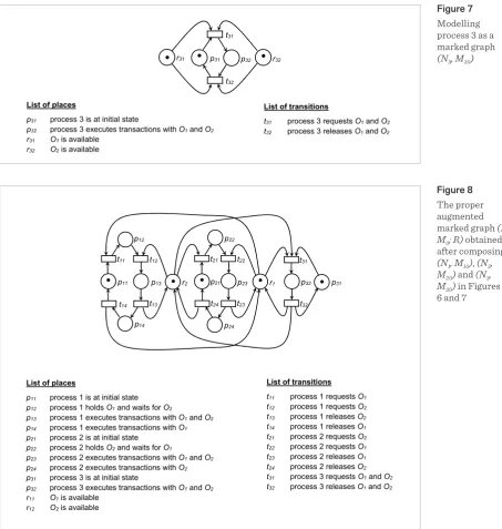
t32 p13 t14 t31 Figure 8 The proper augmented marked graph (N, M0; R) obtained after composing
(N1, M10), (N2, M20) and (N3, M30) in Figures 5, 6 and 7
access both O1 and O2. Once both O1 and O2 are
avail-able, they are locked to prevent accesses from other processes. Update transactions on both O1 and O2 are
then processed. After finishing the update transac-tions, the process releases O1 and O2 simultaneously.
Processes 1, 2 and 3 are represented by the marked graphs (N1, M10), (N2, M20) and (N3, M30), as shown in Figu-
res 5, 6 and 7 respectively. They are live and bounded.
The next step is to compose (N1, M10), (N2, M20) and (N3, M30) via Q1 and Q2. According to Proposition 4, the
integrated PT-net so obtained is a proper augmented marked graph.
Figure 8 shows the proper augmented marked graph
(N, M0; R), where R = {r1, r2}, after fusing r11, r21 and r31
processes. As (N, M0; R) is a proper augmented
mar-ked graph, according to Property 2, it is bounded and conservative. Besides, there exists a R-siphon { r1, r2, p13, p14, p23, p24, p32 } which would become empty after
firing 〈 t11, t21 〉. According to Property 1, (N, M0; R) is
neither live nor reversible. Deadlock will occur after firing 〈 t11, t21 〉. From this, it is concluded that deadlock
would occur among the conflicting processes.
It is also shown that, even though the processes are individually live and reversible, the integrated whole may not be live nor reversible. However, in some cas-es, the integrated whole can be live and reversible, as illustrated in the following example.
Example 2. This example is a revised version of Ex-ample 1. Processes 1, 2 and 3 are revised as follows.
Revised Process 1. At its initial state, the process in-tends to access both O1 and O2. Once both O1 and O2 are
available, they are locked to prevent accesses from oth-er processes. Update transactions on both O1 and O2 are
Figure 9
Modelling the revised process 1 as a marked graph (N1’, M10’)
Figure 10
Modelling the revised process 2 as a marked graph (N2’, M20’)
then processed. After finishing these update transac-tions, the process releases O2. There are some further
update transaction on O1, after with O1 is released. Revised Process 2. At its initial state, the process in-tends to access O2. Once O2 is available, it is locked to
prevent accesses from other processes. The process enters to a state, intending to access O1. Once O1 is
available, it is locked by the process too. Update trans-actions on both O1 and O2 are then processed. After
finishing these update transactions, the process re-leases O1 and O2 simultaneously.
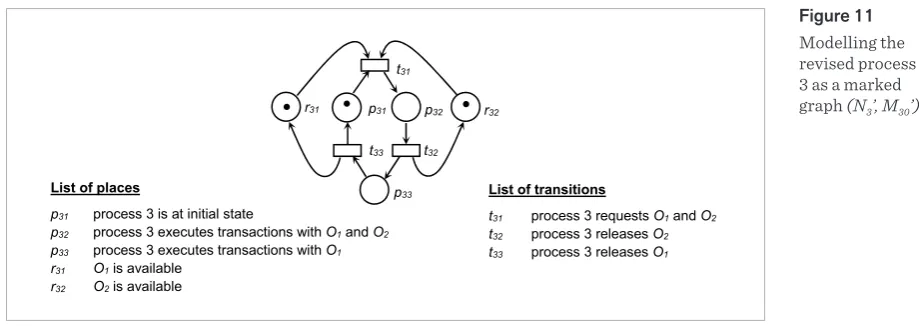
Revised Process 3. At its initial state, the process intends to access both O1 and O2. Once both O1 and
O2 are available, they are locked to prevent accesses
from other processes. Update transactions on both O1
and O2 are then processed. After finishing these
up-date transactions, the process releases O1. There are
some further update transactions on O2, after which O2 is released.
List of places
p11 process 1 is at initial state
p12 process 1 executes transactions with O1 and O2 p13 process 1 executes transaction with O1 r11 O1 is available
r12 O2 is available
List of transitions
t11 process 1 requests O1 and O2 t12 process 1 releases O2 t13 process 1 releases O1
p11
p13 p12
r11 r12
t11
t12 t13
List of places
p21 process 2 is at initial state
p22 process 2 holds O2 and waits for O1
p23 process 2 executes transactions with O1 and O2
r21 O1 is available
r22 O2 is available
List of transitions
t21 process 2 requests O2
t22 process 2 requests O1
t23 process 2 releases O1 and O2
p22
t22
t21
p23
t23
r21
r22 p21
List of places
p21 process 2 is at initial state
p22 process 2 holds O2 and waits for O1
p23 process 2 executes transactions with O1 and O2
r21 O1 is available
r22 O2 is available
List of transitions
t21 process 2 requests O2
t22 process 2 requests O1
t23 process 2 releases O1 and O2
p22
t22
t21
p23
t23
r21
13
Information Technology and Control 2017/1/46
Figure 11
Modelling the revised process 3 as a marked graph (N3’, M30’)
List of places
p31 process 3 is at initial state
p32 process 3 executes transactions with O1 and O2
p33 process 3 executes transactions with O1
r31 O1 is available
r32 O2 is available List of transitions
t31 process 3 requests O1 and O2
t32 process 3 releases O2
t33 process 3 releases O1
t31
p32 r32
r31 p31
t32
p33
t33
The revised processes 1, 2 and 3 are represented by the marked graphs (N1‘, M10‘), (N2‘, M20‘) and (N3‘, M30‘), as
shown in Figures 9, 10 and 11 respectively. They are live and bounded. (N1‘, M10‘), (N2‘, M20‘) and (N3‘, M30) are now
composed via Q1 and Q2. Figure 12 shows the proper
au-gmented marked graph (N‘, M0‘; R‘) where R‘ = {r1, r2},
after fusing r11, r21 and r31 as one single place r1, and r21, r22
and r23 as r2.
Figure 12
The proper augmented marked graph
(N’, M0’; R’)
obtained after composing (N1’, M10’), (N2’, M20’)
and (N3’, M30’)
in Figures 9, 10 and 11
(N’, M0’; R’) represents the integrated whole of the
conflicting processes. As (N’, M0’; R’) is a proper
aug-mented marked graph, according to Property 2, it is bounded and conservative. Besides, every R-siphon in (N’, M0’; R’) would never become empty. According
to Property 1, (N’, M0’; R’) is live and reversible. From
this, it is concluded that the conflicting processes are free from deadlock and capacity overflow.
List of places
p11 process 1 is at initial state
p12 process 1 executes transactions with O1 and O2
p13 process 1 executes transaction with O1
p21 process 2 is at initial state
p22 process 2 holds O2 and waits for O1
p23 process 2 executes transactions with O1 and O2
p31 process 3 is at initial state
p32 process 3 executes transactions with O1 and O2
p33 process 3 executes transactions with O1
r11 O1 is available
r12 O2 is available
List of transitions
t11 process 1 requests O1 and O2
t12 process 1 releases O2
t13 process 1 releases O1
t21 process 2 requests O2
t22 process 2 requests O1
t23 process 2 releases O1 and O2
t31 process 3 requests O1 and O2
t32 process 3 releases O2
t33 process 3 releases O1
p33 t11 r2 p11 p13 p22 t22 t21 p23 t32 r1
p21 p31 p32
t23
p12
t13 t33
t31
t12
List of places
p11 process 1 is at initial state
p12 process 1 executes transactions with O1 and O2
p13 process 1 executes transaction with O1
p21 process 2 is at initial state
p22 process 2 holds O2 and waits for O1
p23 process 2 executes transactions with O1 and O2
p31 process 3 is at initial state
p32 process 3 executes transactions with O1 and O2
p33 process 3 executes transactions with O1
r11 O1 is available
r12 O2 is available
List of transitions
t11 process 1 requests O1 and O2
t12 process 1 releases O2
t13 process 1 releases O1
t21 process 2 requests O2
t22 process 2 requests O1
t23 process 2 releases O1 and O2
t31 process 3 requests O1 and O2
t32 process 3 releases O2
t33 process 3 releases O1
p33 t11 r2 p11 p13 p22 t22 t21 p23 t32 r1
p21 p31 p32
t23
p12
t13 t33
t31
Conclusions
Augmented marked graphs and proper augmented marked graphs possess a special structure as well as many desirable properties pertaining to liveness, boundedness, reversibility and conservativeness. They are useful for modelling and analyzing distrib-uted systems with shared resources.
Based on composition of live and bounded marked graphs, new characterizations for proper augmented marked graphs are proposed. Conflicting processes of a distributed system can be first modelled as live and bounded marked graphs, and then composed via common resource places to form a proper augmented marked graph which represents the integrated whole. As proper augmented marked graphs are bounded and conservative, it is assured that capacity overflow would never occur. By checking R-siphons, liveness and reversibility can be effectively analyzed.
As compared to other well-known subclasses of Pe-tri nets such as state machines, marked graphs, free choice nets and asymmetric choice nets, augmented marked graphs or proper augmented marked graphs are not widely used in system modelling and analysis
despite possessing many desirable properties per-taining to liveness, boundedness, conservativeness and reversibility. This is because of their complicat-ed definition which is rather difficult to comprehend, thus undermining the usability. There is also a lack of simple but formal methodology for modelling, in-tegrating or analyzing conflicting processes or com-ponents using augmented marked graphs or proper augmented marked graphs.
The problems can be resolved by characterizing prop-er augmented marked graphs by the composition of live and bounded marked graphs. With the charac-terizations, conflicting processes of a distributed sys-tem can be readily modelled, composed and analyzed. This paper provides a theoretical foundation of these characterizations, and shows the modelling and anal-ysis using typical examples of distributed transaction processing.
Acknowledgments
The author would like to thank the anonymous re-viewers for their helpful suggestions.
References
1. F. Chu, X. Xie. Deadlock Analysis of Petri Nets using Siphons and Mathematical Programming. IEEE Trans-actions on Robotics and Automation, 1997, 13(6), 793-804. https://doi.org/10.1109/70.650158
2. K. S. Cheung. New Characterization for Live and Re-versible Augmented Marked Graphs. Information Processing Letters, 2004, 92(5), 239-243. https://doi. org/10.1016/j.ipl.2004.05.018
3. K. S. Cheung, K. O. Chow. Cycle-Inclusion Property of Augmented Marked Graphs. Information Processing Letters, 2005, 94(6), 271-276. https://doi.org/10.1016/j. ipl.2005.02.011
4. K. S. Cheung. Boundedness and Conservativeness of Augmented Marked Graphs. IMA Journal of Mathe-matical Control and Information, 2007, 24(2), 235-244. https://doi.org/10.1093/imamci/dnl019
5. C. L. Chen, S. C. Chin, H. C. Yen. Reachability Analysis of Augmented Marked Graphs via Integer Linear Pro-gramming. Computer Journal, 2010, 53(6), 623-633. https://doi.org/10.1093/comjnl/bxp003
6. K. S. Cheung. Augmented Marked Graphs. Springer, 2014.
7. H. J. Huang, L. Jiao, T. Y. Cheung. Property-Preserving Composition of Augmented Marked Graphs that Share Common Resources. IEEE Proceedings of the Interna-tional Conference on Robotics and Automation, 2003, 1446-1451. https://doi.org/10.1109/robot.2003.1241795 8. K. S. Cheung. A Synthesis Method for Designing
Shared-Resource Systems. Computing and Informat-ics, 2005, 24(6), 629-653.
9. K. S. Cheung. Modelling and Analysis of Manufacturing Systems Using Augmented Marked Graphs. Informa-tion Technology and Control, 2006, 35(1), 19-26. 10. K. S. Cheung. Composition of Augmented Marked
Graphs and Its Application to Component-Based Sys-tem Design. Information Technology and Control, 2007, 36(3), 310-317.
15
Information Technology and Control 2017/1/46
Journal of Computer Systems Science and Engineer-ing, 2007, 22(6), 349-358.
12. K. S. Cheung. Component-Based System Integra-tion using Proper Augmented Marked Graphs. In: X. Zhang, H. Liu, Z. Chen, N. Wang (eds.), Intelligent Ro-botics and Applications, Lecture Notes in Artificial Intelligence, Springer, 2014, 8917, 498-509. https://doi. org/10.1007/978-3-319-13966-1_49
13. W. Reisig. Petri Nets: An Introduction. Springer, 1985. https://doi.org/10.1007/978-3-642-69968-9
14. T. Murata. Petri Nets: Properties, Analysis and Appli-cations. Proceedings of IEEE, 1989, 77(4), 541-580. https://doi.org/10.1109/5.24143
15. W. Reisig. Understanding Petri Nets. Springer, 2013. https://doi.org/10.1007/978-3-642-33278-4
16. J. Desel, J. Esparza. Free Choice Petri Nets. Cam-bridge University Press, 1995. https://doi.org/10.1017/ CBO9780511526558
Summary / Santrauka
Augmented marked graphs possess a special structure for modelling distributed systems with shared resourc-es. Not only inheriting the desirable properties of augmented marked graphs such as on liveness and revers-ibility, proper augmented marked graphs also exhibit other desirable properties, including boundedness and conservativeness. However, proper augmented marked graphs have a rather complicated definition that inev-itably undermines the usability in system modelling. In this paper, based on composition of live and bounded marked graphs, new characterizations for proper augmented marked graphs are devised. Through these char-acterizations, proper augmented marked graphs can be effectively used in modelling and analyzing conflicting processes of a distributed system. Applications to distributed transaction processing with shared resources are discussed.